The simplest memorization technique is mnemonic rules. They help to understand a complex action through simple representation or comparison. The article will give a detailed description of what the gimlet rule is and briefly and clearly describe its basic definition.
A description of the application of this rule to justify various physical laws will also be given. Additionally, a description of the left-hand rule and two mnemonic algorithms for determining the direction of electromagnetic induction will be given.
Definition
The author of the gimlet rule is theoretical physicist Pyotr Sigismundovich Buravchik. With its help, the direction of the axial vector with a known basis vector was determined. This rule is used in the case of mnemonic definition using the right and left hands.
This rule is a mnemonic algorithm for establishing electromagnetic induction, based on the established direction of movement of the electric current, which is the exciter of magnetic fields.
This rule can be explained more briefly and clearly as follows:
- The gimlet is pointed downward and screwed in clockwise.
- Its tip imitates the direction vector of electric current.
- At the moment of screwing, the orientation of the magnetic induction lines coincides with the direction of movement of the gimlet handle.
The generally accepted rule is that the direction of movement of the coil is to the right. Accepting this fact, we can conclude: when the current moves along the shortest path in one direction, namely from a positive value to a negative value, the magnetic induction lines will be directed to the right. The condition is relevant for a direct conductor.
The gimlet rule has two main varieties:
- Right hand rule.
- Left hand rule.
Next, an explanation and a concrete example will be given for easier understanding.
Determination of magnetic field
When studying electrical phenomena in 8th grade, you learned that in the space around a charged body there is a field called electric, and that it is through this field that electrical interaction between charged bodies and particles occurs.
There is also a field near a magnetized body and near a conductor carrying current - it is called magnetic. Magnetic interaction occurs at a certain speed through a magnetic field (the first to come to this conclusion was the English physicist Michael Faraday (1791-1867)).
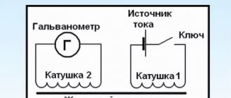
Rice. 1.3. Coils carrying current behave like permanent magnets
Let's consider the interaction of a permanent magnet and a coil with current (Fig. 1.3, b). A coil carrying current creates a magnetic field. The magnetic field spreads in space and begins to act on a permanent magnet (magnetized body) - the magnet is deflected. The magnet also creates its own magnetic field, which, in turn, acts on the current-carrying coil, and the coil also deflects.
Note that a magnetic field also exists near any moving charged particle and near any moving charged body and acts with some force on charged bodies and particles moving in this magnetic field.
Please note: we cannot see the magnetic field, but at the same time it, like the electric field, is absolutely real - it is a form of matter.
A magnetic field is a form of matter that exists near magnetized bodies, current-carrying conductors, moving charged bodies and particles and acts on other magnetized bodies, current-carrying conductors, moving charged bodies and particles located in this field.
Let's summarize:
Bodies that retain their magnetic properties for a long time are called permanent magnets. The main properties of permanent magnets: 1) the magnetic effect of a magnet is most pronounced near its poles; 2) like poles of magnets repel, unlike poles attract; it is impossible to obtain a magnet with only one pole; 3) when a permanent magnet is heated to a certain temperature (Curie point), its magnetic properties disappear.
Magnetic interaction is carried out through a magnetic field. A magnetic field is a form of matter that exists near magnetized bodies, current-carrying conductors, moving charged bodies and particles and acts on magnetized bodies, current-carrying conductors, moving charged bodies and particles located in this field.
Magnetic field induction, magnetic induction lines
We cannot see the magnetic field, but to better understand magnetic phenomena it is important to learn how to depict it. Magnetic needles will help with this. Each such arrow is a small permanent magnet that easily rotates in a horizontal plane (Fig. 2.1). You will learn from this paragraph how the magnetic field is graphically depicted and what physical quantity characterizes it.
Rice. 2.1. A magnetic needle is a permanent magnet. The dotted line shows the axis of the magnetic needle
Magnetic field strength characteristic
If a charged particle moves in a magnetic field, then the field will act on the particle with some force. The magnitude of this force depends on the charge of the particle, the direction and speed of its movement, and also on how strong the field is.
The strength characteristic of a magnetic field is magnetic induction.
Magnetic induction (magnetic field induction) is a vector physical quantity that characterizes the force action of a magnetic field.
Magnetic induction is indicated by the symbol
The SI unit of magnetic induction is tesla ; named after the Serbian physicist Nikola Tesla (1856-1943):
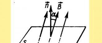
Rice. 2.2. In a magnetic field, magnetic arrows are oriented in a certain way: the north pole of the arrow indicates the direction of the magnetic field induction vector at a given point
The direction of the magnetic induction vector at a given point of the magnetic field is taken to be the direction indicated by the north pole of the magnetic needle installed at this point (Fig. 2.2).
Note! The direction of the force with which the magnetic field acts on moving charged particles or on a current-carrying conductor, or on a magnetic needle, does not coincide with the direction of the magnetic induction vector.
How to express 1 Tesla through other SI units, what formula can be used to determine the magnetic induction module, and the direction of the force with which the magnetic field acts on a current-carrying conductor.
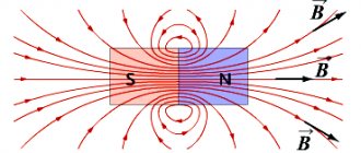
Magnetic lines:
- outside the magnet they leave the north pole of the magnet and enter the south pole;
- always closed (the magnetic field is a vortex field);
- most densely located at the poles of the magnet;
- never intersect
Rice. 2.3. Magnetic field lines of a strip magnet
Magnetic field image
In Fig. 2.2 we see how magnetic needles are oriented in a magnetic field: their axes seem to form lines, and the magnetic induction vector at each point is directed along the tangent to the line passing through this point.
Conditional directed lines, at each point of which the tangent coincides with the line along which the magnetic induction vector is directed, are called magnetic induction lines or magnetic lines .
Magnetic fields are graphically depicted using magnetic lines:
- the direction of the magnetic induction line at a given point is taken to be the direction of the magnetic induction vector;
- The larger the magnetic induction module, the closer the magnetic lines are drawn to each other.
Having examined the graphical representation of the magnetic field of a strip magnet, we can draw some conclusions (see Fig. 2.3). Note that these conclusions are valid for the magnetic lines of any magnet.
The pattern of magnetic lines can be reproduced using iron filings. Let's take a horseshoe magnet, put a plexiglass plate on it and pour iron filings onto the plate through a strainer. In a magnetic field, each piece of iron will be magnetized and turn into a small “magnetic needle”. Improvised “arrows” are oriented along the magnetic lines of the magnet’s magnetic field (Fig. 2.4).
Rice. 2.4. Chains of iron filings reproduce the pattern of magnetic induction lines of the magnetic field of a horseshoe magnet
Rice. 2.5. An area where the magnetic field is uniform
Uniform magnetic field
A magnetic field in a certain part of space is called homogeneous if at each point the magnetic induction vectors are the same both in magnitude and in direction (Fig. 2.5).
Rice. 2.6. The magnetic field inside a strip magnet (a) and between two magnets facing each other with opposite poles (b) can be considered uniform
In areas where the magnetic field is uniform, the magnetic induction lines are parallel and located at the same distance from each other (Fig. 2.5, 2.6). Magnetic lines of a uniform magnetic field directed towards us are usually depicted as dots (Fig. 2.7, a) - it is as if we see “arrowheads” flying towards us. If magnetic lines are directed away from us, then they are depicted with crosses - it’s as if we see the “feathers of arrows” flying away from us (Fig. 2.7, b).
In most cases, we are dealing with a non-uniform magnetic field - a field at different points of which the magnetic induction vectors have different values and directions. The magnetic lines of such a field are curved, and their density is different.
Rice. 2.7. Image of magnetic induction lines of a uniform magnetic field, which are perpendicular to the plane of the drawing and directed towards us (a); directed from us (b)
Earth's magnetic field
To study terrestrial magnetism, William Gilbert made a permanent magnet in the form of a ball (model of the Earth). Having placed a compass on the ball, he noticed that the compass needle behaves in the same way as on the surface of the Earth.
Experiments allowed the scientist to suggest that the Earth is a huge magnet, and its south magnetic pole is located in the north of our planet. Further research confirmed W. Gilbert's hypothesis.
In Fig. Figure 2.8 shows a picture of the magnetic induction lines of the Earth's magnetic field.
Rice. 2.8. Layout of magnetic lines of the magnetic field of planet Earth
The magnetic induction lines of the Earth's magnetic field are not parallel to its surface. If you fix the magnetic needle in a gimbal, that is, so that it can rotate freely around both the horizontal and vertical axes, the needle will be installed at an angle to the surface of the Earth (Fig. 2.9).
Rice. 2.9. Magnetic needle in gimbal
The Earth's magnetic field has long helped travelers, sailors, military personnel and others to navigate. It has been proven that fish, marine mammals and birds orient themselves according to the Earth’s magnetic field during their migrations. Some animals, such as cats, also navigate when looking for the way home.
- Order solutions to physics problems
Magnetic storms
Studies have shown that in any area the Earth's magnetic field changes periodically, every day. In addition, small annual changes in the Earth's magnetic field are observed. However, there are also sudden changes. Strong disturbances in the Earth's magnetic field, which cover the entire planet and last from one to several days, are called magnetic storms. Healthy people practically do not feel them, but for those who have cardiovascular diseases and diseases of the nervous system, magnetic storms cause a deterioration in their well-being.
The Earth's magnetic field is a kind of “shield” that protects our planet from charged particles flying from space, mainly from the Sun (“solar wind”). Near the magnetic poles, streams of particles fly quite close to the Earth's atmosphere. With increasing solar activity, cosmic particles enter the upper layers of the atmosphere and ionize gas molecules - auroras are observed on Earth (Fig. 2.10).
Rice. 2.10. As solar activity increases, the area of dark spots on the Sun increases (a), and magnetic storms and auroras occur on Earth (b)
Let's summarize:
Magnetic induction is a vector physical quantity that characterizes the force action of a magnetic field. The direction of the magnetic induction vector coincides with the direction to which the north pole of the magnetic needle points. The SI unit of magnetic induction is tesla (T).
Conditional directed lines, at each point of which the tangent coincides with the line along which the magnetic induction vector is directed, are called magnetic induction lines or magnetic lines.
Magnetic induction lines are always closed, outside the magnet they leave the north pole of the magnet and enter the south pole, and are denser in those areas of the magnetic field where the magnetic induction module is greater.
Planet Earth has a magnetic field. Near the Earth's north geographic pole is its south magnetic pole, and near its south geographic pole is its north magnetic pole.
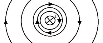
Magnetic field of current
You already know that there is a magnetic field near a current-carrying conductor. Let's study the magnetic field of a straight conductor carrying current. To do this, we pass the conductor through a sheet of cardboard (perpendicular to the sheet), sprinkle iron filings on the cardboard and close the circuit. In the magnetic field of the conductor, the sawdust will be magnetized and recreate the picture of the magnetic induction lines of the magnetic field of a straight conductor with current - concentric circles surrounding the conductor (see Fig. 3.1). How to determine the direction of magnetic lines?
Right hand
The right-hand rule is used to mnemonicly determine the direction of movement of electromagnetic induction. The formulation of this algorithm is as follows: you need to clench your palm into a fist and raise your thumb up. In this gesture, the finger imitates an electrical conductor and the direction of movement of electric current. And 4 clenched fingers indicate the direction of the magnetic induction lines.
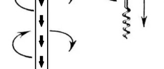
In physics, the gimlet is considered to be the standard. For easier understanding, this tool can be represented as a screw, a screw with a right-hand thread, or a drill.
The gimlet rule is not a definitive definition. It can be interpreted very differently when it is necessary to determine angular velocity, magnetic induction, mechanical rotation and angular momentum.
What is the gimlet rule?
Gimlet - a tool for drilling holes
It sounds like this: in cases where the direction of the gimlet coincides with the direction of the current in the conductor during translational movements, then at the same time the direction of rotation of the handle of the gimlet will be identical to it.
Product vector
Gimlet can help with the next question - determining the vector product. In this case, this rule is interpreted as follows:
- Two vectors have a common starting point, but a different direction.
- The 1st vector factor must be rotated along the shortest path until it is in relation to the 2nd vector factor.
- During this rotation, the screw will rotate towards the vector product.
This rule also takes into account the right-handed orientation of the gimlet thread. This rule also applies to clockwise direction. If you rotate the vector factor clockwise until it and the second vector factor are aligned, then the direction of movement will depend on who is rotating this vector. The rotation will also be carried out inside the plane (clock).
To visualize, you need to spread the thumb, middle and index fingers on your right hand. When this rule is applied in electrodynamics, the following can be obtained:
When all three fingers are displaced, we obtain clockwise movement, as well as the sum of the products of all vectors.
Explanation of the name
Most people remember mention of this from a physics course, namely the electrodynamics section. This happened for a reason, because this mnemonic is often given to students to simplify their understanding of the material. In fact, the gimlet rule is used both in electricity, to determine the direction of the magnetic field, and in other sections, for example, to determine angular velocity.
A gimlet is a tool for drilling small-diameter holes in soft materials; for a modern person, it would be more common to use a corkscrew as an example.
Important! It is assumed that the gimlet, screw or corkscrew has a right-hand thread, that is, the direction of its rotation when tightened is clockwise, i.e. to the right.
The video below provides the full formulation of the gimlet rule, be sure to watch it to understand the whole point:
Basis
Basis - several vectors located in space. In this case, the basis vectors represent an ordered set. Under this condition, any of the vectors can be represented once as a linear combination of all vectors from this set. The basis mnemonic algorithm is as follows: the gimlet is twisted to the right, while the X basis moves along a short path to the Y basis, and therefore towards the Z basis.
For the right hand rule it would look like this:
- The middle finger is the X base. It moves towards the index finger or Y base.
- With this movement, the direction is right-handed, which means it is directed towards the Z base.
For bases, you can also use the clock dial rule, but only with the use of three hands and when the direction of rotation is to the right. Left orientation is taken into account only under a specifically stated condition.
Looking for direction
To figure it out, you still have to remember your school lessons. At them, physics teachers told us that electric current is the movement of elementary particles, which at the same time carry their charge along a conductive material. Thanks to the source, the movement of particles in the conductor is directed. Movement, as we know, is life, and therefore nothing more than a magnetic field arises around the conductor, and it also rotates. But how?
The answer is given by this very rule (without using any special tools), and the result turns out to be very valuable, because depending on the direction of the magnetic field, a couple of conductors begin to act according to completely different scenarios: either repel each other, or, on the contrary, rush towards each other.
Solenoid
The right-hand rule also allows you to determine which direction the magnetic field is in solenoids and inductors. Coils also consist of wire, but the difference is that this wire is wound into a spiral, which means it does not have a direct direction. Also, in the presence of a magnetic core that interacts with current, the value of the magnetic field strength increases significantly. In order to determine the direction of the magnetic field lines in the solenoid, it is necessary:
- The wire in the coil has the value "I" and is a conductor of electric current.
- Current flows through the coil from a higher potential to a lower one, and therefore from “+” to “−”. In this case, the coil is vector "B".
- We take the coil with our right hand and extend our thumb along the element itself.
This rule is interpreted as follows: the coil has a magnetic induction vector “B”, the direction of which coincides with the direction of the thumb. The 4 fingers holding the coil indicate the direction of flow of electric current. This rule is also based on the right-hand twisting of the gimlet. This orientation can be used when performing various experiments when calculations are not required and using left-handed orientation, which is taken into account in advance.
Determining the direction of current with a gimlet
As mentioned above, the direction of the current can be determined based on the PB. This is done as follows:
- Your right hand should take the guide;
- After this, you need to stick out four fingers in the direction of the magnetic field lines;
- Then your thumb raised up will indicate the direction of the electric current.
Quite convenient step-by-step instructions, isn’t it?
In addition, by reformulating our statement, we can determine the direction of the magnetic induction vector, which will be discussed in more detail in the paragraph below.
Rule for angular velocity
The principle of the right-hand rule can be applied if you need to determine the angular velocity of a rotating object. First you need to consider:
- Velocity vector "v".
- Angular velocity vector "ω".
- A vector that is drawn from a fixed point to a given “r”.
All these parameters are interconnected by a vector product. The formula we use for this product will be as follows:
The formulation of angular velocity when using the gimlet rule sounds like this. If you rotate the gimlet in the direction in which the body is rotating, then the direction of screwing will show the direction of the angular velocity of this body. In the case of right rotation of the gimlet, the angular velocity will be directed to the right and vice versa.
Using the right hand rule, this formulation is interpreted more simply: if you hold a rotating body in your right hand, then the thumb will indicate the direction vector of the angular velocity, and the other 4 fingers will point to the direction of rotation.
Notes
- For mathematical details of the general concept of basis orientation discussed here, see the article Orientation.
- By determining the direction here, we mean the choice of one of two opposite directions (the choice between just two opposite vectors), that is, it comes down to the choice of the positive direction.
- This means that other rules may also be convenient in any number, but their use is not necessary.
- This means that you can use the opposite rule if you wish, and sometimes this can even be convenient.
- The concept of a right and left basis extends not only to orthonormal bases, but to any three-dimensional bases (that is, to oblique Cartesian coordinates too), however, for simplicity, we will limit ourselves here to the case of orthonormal bases (rectangular Cartesian coordinates with equal scales along the axes).
- You can verify that in general this is indeed the case, based on the elementary definition of a vector product: A vector product is a vector perpendicular to both factor vectors, and in magnitude (length) equal to the area of the parallelogram. The same thing, which of two possible vectors perpendicular to two given ones should be chosen is the subject of the main text; the rule that allows this to be done and complements the definition given here is indicated there.
- Left-hand threads are used in modern technology only when the use of right-hand threads would lead to the danger of spontaneous unscrewing under the influence of constant rotation of the part in one direction - for example, left-hand threads are used at the left end of the bicycle wheel axle. In addition, left-hand threads are used in reducers and cylinders for flammable gases to eliminate the connection of a flammable gas reducer to the oxygen cylinder.
- In addition, in their cases, they can be more convenient than the general rule, and are even sometimes formulated organically enough to be especially easy to remember; which, however, apparently still does not make memorizing them all any easier than memorizing just one general rule.
- Even if we are dealing with a fairly asymmetrical (and asymmetrically located relative to the axis of rotation) body, so that the coefficient of proportionality between the angular velocity and angular momentum is the inertia tensor, which is not reducible to a numerical coefficient, and the angular momentum vector is then generally speaking not parallel to the angular velocity vector, however, the rule works in the sense that the direction is given approximately, but it is enough to make a choice between two opposite directions.
- Strictly speaking, with this comparison there is also a constant coefficient of 2, but in this topic this is not important, since we are now talking only about the direction of the vector, and not about its magnitude.
- Not a mandatory requirement.
Next
MiscellaneousWhat is an RCD?
Moment of power
The gimlet rule is applicable to determine the moment of force. The moment of force is calculated using the following formula:
The following quantities are used in this expression:
- M is the moment of force;
- ri is a vector or radius applied to point i.
- Fi is the force applied to point i.
The rule for a gimlet applied to the moment of force is interpreted as follows: if the gimlet is screwed in the direction in which the forces are trying to rotate the body, it will screw in precisely in the direction of the moment of the acting forces. For example, when screwing a screw, it will be screwed in the direction of rotation of the screwdriver handle, since this direction is created by the force of the movement of the person’s hand.
The moment of force can be determined visually. The version of the right hand rule used in this case will be as follows: if you take an object in your right hand, squeeze it and put your thumb forward, then 4 fingers will point to the direction of the circular motion of the body, and the thumb to the direction of the moment of force.
Left and right coordinate system
Vector rectangular coordinate indicators are taken to calculate the state of various segments. In this case, the ordinate and abscissa of the targeted beam correspond to the initial position of the point and coincide with the final characteristics.
If the initial and final coordinates of the vectors do not match, then do the following:
- transfer of a directed segment so that its beginning coincides with the origin of the coordinate region;
- subtracting the ordinate and abscissa values of the edge of a segment from the system indicators of the beginning of the ray instead of moving the starting point.
In accordance with the gimlet rule, finding a segment on the coordinate plane corresponds to a vector stereo projection onto the main rod and allows you to use the right hand pattern. The measurement tasks are tacitly specified in each individual case. These patterns relate to conventional concepts, but the vector combination is selected taking into account the same scale of the Cartesian plane in the direction of any axes.
In this case, you need to follow certain rules:
- a left-ordered vector set is used if using a right-sided cluster is not possible;
- the left and right vector sets are congruent in mirror vision.
The rules are applied to calculate the path of the vector product and the laws of constructing rays in the plus direction. This method of determination makes sense with a direct current conductor. The principle does not work in relation to the class of induction coils, when the current guide represents the windings of the structure and is not straight.
Vector artwork
The result is determined by the principle of the gimlet and the right palm, when the segments are displayed with the same sources, and the rotation of the first ray follows a short path to the next vector. In this case, the screw is turned along the path following the base of the result of vector multiplication. In the form of a gimlet, hardware with a right-hand spiral cut is used.
If, when placing the conductor in the right hand, the fingers are folded onto the rod, then they determine the path of the spirals, and the thumb shows the direction of the basis product. Sometimes the rays coincide with the sources at a certain point. In this case, the thumb shows the course of the first segment (participant in the work), the index finger is located along the second ray, and the middle finger, according to the pattern of the gimlet, will determine the direction of the result from the multiplication of vectors.
Rays and spatial indicators
The vector interaction of two beams in a three-dimensional region is determined by the section of the beam that is in a perpendicular position to their initial modules. The length of the vector product is calculated as the area of a rectangle or parallelogram located between the original segments. The course of the rays is taken so that the first 3 resulting vectors are located on the right. If one of them has a zero exponent, then the result of the multiplication tends to zero.
The gimlet rule or the patterns of the left and right hands do not apply to mandatory standards for the operation of electrical equipment. Sometimes the characteristics of magnetic space are determined using vector ratio formulas. You should know the following:
- The gimlet's law involves turning the screw and the beam so that the first vector tends to merge with the second along the shortest path: the direction of the screw will show the path of the third right basis.
- According to the principle of the right palm, with parallel arrangement of sections along the lines, the thumb is located along the right ray (X), the index finger lies along the course of the second segment (Z). The middle finger will indicate the position of the third vector along the (Y) axis, and the union of the vectors will be located to the right of the central axis.
To use the gimlet rule, the observer must have a little imagination to mentally draw the turns and place the fingers correctly.
Finding electromotive force
EMF occurs when a conductor crosses an electromagnetic field or in the event of transformation of the properties of potential space. Force is measured by the rate of change of magnetic current. Increasing or decreasing the current reforms the generated flux, which interacts with neighboring conductors.
The direction of the induced emf is determined by the right palm rule. The hand with the conductor is placed so that the potential lines enter the hand, and the outstretched finger determines the direction of the wire. Straightened 4 fingers will indicate the path of current flow in a closed circuit.
If the gimlet is turned along the course of the spatial vortex at the point where the vectors arise, then its translational movement will indicate the path of rotation of the engine rotor. This can be seen if four fingers of the right hand are squeezed in the direction of the vortex. A bent finger will show the desired path.
Ampere's law
The left-hand principle for Ampere's law states that if a conductor is placed between two magnets, an electromagnetic force acts on it, pushing out a charge or displacing the conductor from a given position.
Using the left hand, this rule can be described more simply: the palm assumes a horizontal position. At this moment, the magnetic induction will be perpendicular to the palm. In this position, the thumb bent by 900 shows the direction of the acting force, and the remaining fingers show the direction of the electric current in the conductor.
When calculating the Ampere force, we use the following formula:
This formula uses the following quantities:
- Fa - Ampere force;
- B—magnetic induction;
- I - current strength;
- ΔL is the length of the conductor;
- a is the angle between the directions of electric current and magnetic induction.
This law is applied in the design of electric motors and alternating current generators.
Lorentz force
The left-hand rule allows you to display the direction of the Lorentz force. This parameter determines the magnitude of the impact of the magnetic field on charged particles in the conductor. Using simple words, this physical phenomenon can be interpreted as follows: moving charged particles are affected by magnetic induction. The direction of action of these forces is strictly perpendicular to the direction of particle motion.
Using your left hand, you can visually determine the direction of influence of the magnetic induction lines. This is done as follows:
- The left palm is straightened, with the thumb at a 90-degree angle. The palm is a conductor, which is perpendicularly affected by the forces of electromagnetic induction (vector B).
- The thumb points to the direction of the Lorentz force (vector Fl).
- 4 straightened fingers indicate the direction of the positive charge. Provided that a negative charge flows through the conductor, the direction of movement will be towards the palm, and not away from it. This condition is very important in calculations.
The Lorentz force is calculated using the following formula:
In this formula:
- Fl - Lorentz force;
- q is the amount of charge;
- v is the speed of charge movement;
- B—magnetic induction;
- a is the angle between the direction of particle motion and magnetic induction.
The calculation takes into account the parameter of particles that flow through the conductor. Also, the direction of particle movement is taken into account.
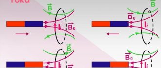
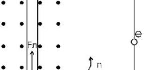
Branching of the interaction of conductors with current in ampere experiments
When Oersted discovered the occurrence of induction in a current-carrying conductor, Ampere was inspired and began his research. The scientist conducted a series of experiments with parallel conductors, in which he proved that a magnetic field is formed around a charged particle. Thanks to his observations, he came to the conclusion that if current is passed through conductors in one direction, then they attract, and if in different directions, they repel.
This can be explained using the gimlet rule. In the first case, it is clear that the magnetic fields of each conductor go towards the observer at a point between them, the inductions interfere with each other, and the wires repel. And vice versa in the second case: at the point where the lines on the right conductor go towards the observer, on the left they go away from him.