Content
A magnetic field occurs when we have moving electric charges. But we cannot see or feel it with our senses.
Physics can give us such an amazing opportunity - to see the magnetic field. We will also be able to determine its shape, how and where it is located, and somehow characterize it.
For this we will not need any complex instruments, but just iron filings. In this lesson we will look at their application and draw certain conclusions about the direct current magnetic field.
Using iron filings to detect magnetic field
A magnetic field arises around conductors through which current flows. There are many ways to detect it, some of which we discussed in the last lesson.
Now we will look at another method - using small iron filings.
Why can iron filings be used to study the magnetic field? The answer is very simple: these small pieces of iron, once in a magnetic field, become magnetized - they become small magnetic needles .
Oersted's experiment has already shown us that the magnetic needle deviates from its original position when there is a nearby conductor through which current flows. Now we will have not one such arrow, but a large number of them. We can observe how the axis of each such arrow will be established under the action of magnetic field forces.
Answer
Take a sharpened pencil. Imagine that a current can flow through a pencil and it flows from the blunt end to the tip. Grasp it with your RIGHT hand so that the bent thumb points towards the point. In which direction do the other fingers turn to grasp? This is the DIRECTION of the MAGNETIC field line of a given current.
So, the RIGHT hand is the grasper.
Now straighten your LEFT HAND, connecting four fingers, and bending the thumb perpendicular to the other four fingers. Now our pencil will play the role of a vector of the EXTERNAL magnetic field. Let this vector enter the palm of your LEFT hand, perpendicular to it. (You poke your palm with the point of a pencil) In this case, the palm (its plane) will have a very definite orientation in space. Imagine that you pierced your palm and it (the palm) can spin on the pencil like a piece of kebab on a skewer. ROTATE your palm so that the FOUR folded fingers show the DIRECTION of the current. A bent finger will show the direction of AMPERE FORCE or LORENTZ FORCE (The direction of current is the movement of POSITIVE charges, a whole bunch of charges is Ampere, and a single charge is Lorentz)
LEFT arm is paralyzed. IT CANNOT BE BENDED.
Let's summarize. The right grip determines the magnetic field of the current, the Left paralysis determines the direction of the force from the external magician. fields for current or MOVING charge.
Superposition principle – Common field – VECTOR sum of all fields. You can only add HOMOGENEOUS quantities. You CANNOT add an electric field to a magnetic one, or a gravitational field to an electric one.
I hope I explained it clearly, but the fact that it’s a little with a “bloody” slant, so when you poke yourself in the palm with the tip, you’ll immediately remember the rule)))
Determining the shape of the magnetic field
What does a magnetic field “look” like? Let's do a simple experiment (Figure 1).
We have a straight conductor carrying current. Let's make a hole in a sheet of cardboard and thread our conductor through it. Place a thin layer of iron filings on the cardboard and turn on the current.
What will we see? How are the iron filings now located in a direct current magnetic field?
Figure 1. Arrangement of iron filings in a direct current magnetic field
Under the influence of a magnetic field, the sawdust will take an interesting position. They no longer lie randomly on a sheet of cardboard, but are located around the conductor in concentric circles.
Inhomogeneous and homogeneous magnetic field
If we return to the research of G.Kh. Oersted and observe the behavior of the arrow at various points, you can notice that the further the arrow is removed from the conductor, the less it deviates. This means that the field weakens with distance from the source.
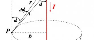
What the magnetic field lines of a current-carrying conductor look like is shown in Figure 5. The reader is presented with a cross-section of a conductor with current flowing “into the drawing.” In this case, the field lines are concentric circles. Where the field is more intense (close to the source - conductor) the lines are drawn thicker, and in areas where it is weaker - less often.
Figure 5 – Magnetic field lines of a current-carrying conductor
A field that acts on a magnetic needle with the same force at different points in space is called uniform.
In the opposite situation, they speak of a non-uniform magnetic field.
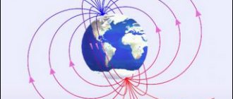
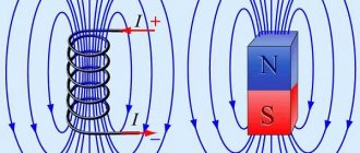
Strictly speaking, the magnetic field is almost always inhomogeneous. Nevertheless, the field created by some sources can be considered homogeneous in some small area. For example, the field in the area between magnets located in series (see Figure 6). The induction lines of a uniform magnetic field are parallel, and the density with which they are depicted does not change.
Figure 6 – Field between two magnets in series
Magnetic field lines
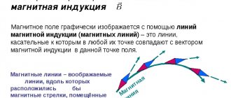
To describe the magnetic field and the circles of iron filings it creates, we will introduce a new definition - magnetic lines .
Magnetic field lines are the lines along which the axes of small magnetic needles are located in the magnetic field.
That is, if we connect the sawdust that formed one of the circles with an imaginary line, we will get a circle with a conductor in the center (Figure 2).
Figure 2. Direct current magnetic field lines
Please note that the arrows not only line up along these lines, but are also all oriented in the same direction along this circle. To make it easier to evaluate this, ordinary magnetic needles can be placed next to the conductor, as in Figure 2.
They are located on the magnetic field line, pointing one pole in one direction . Here we are not saying that they point to the right or to the left. They unfold with one pole, as if in one direction of movement around the circle.
Electrodynamics and magnetostatics
Magnetic induction is a vector factor that characterizes a force field. The value shows the influence of the magnetic background on negatively and positively charged particles in the space under study. Induction determines the strength of the field's influence on a charge moving at a given speed. For this case, the application laws are described as follows:
- Screw rule. If the forward circular motion of the gimlet coincides with the direction of the charged electrons in the coil, then the path of rotation of the tool handle will coincide with the course of the magnetic vector of polar induction, the direction depending on the current.
- Right hand principle. If you take the rod in your right hand so that the finger set at a right angle shows the course of the current, then the other fingers will correspond to the direction of the magnetic induction beam produced by the current. The path of the magnetic induction vector is laid tangent to the line of segments.
For a moving conductor
A metal rod contains a large number of free electrons, the movement of which is characterized as chaotic. If the coil moves in an electromagnetic force field along the lines, then the background deflects electrons moving simultaneously with the conductor. Their movement creates EMF (electromotive force) and is called electromagnetic induced induction.
Under the influence of induction, charged particles move and accumulate at one end of the rod, while a shortage of electrons appears at the other. As a result of this situation, a positive charge is generated and a potential difference arises, and electrical voltage appears.
Current will flow under the influence of a potential difference when such a coil is connected to an external circuit in a closed circuit. When the rod moves in the direction of the field lines, the effect of the field on the charges is reduced to zero. There is no electromotive force, no voltage, no electron current.
Direction of magnetic lines and shape of the magnetic field
It turns out that the use of sawdust gave us two new characteristics of the magnetic field: we see not only its shape using magnetic lines, but also notice that the lines themselves have a certain direction.
So, we can draw the following conclusions:
The magnetic lines of the current magnetic field are closed curves (concentric circles in the case of a direct current magnetic field) surrounding the conductor.
The direction indicated by the north pole of the magnetic needle at each point in the field is taken to be the direction of the magnetic field line.
Relationship between the directions of magnetic lines and the direction of electric current
Magnetic lines give us the opportunity to depict the magnetic field graphically.
At what distance from the conductor can we draw its magnetic lines? The answer is simple - for a graphic image we can use a scale that is convenient for us.
A magnetic field exists at all points in space surrounding a current-carrying conductor. This means that we can legally draw a magnetic line through any point.
Okay, but how to determine the direction of magnetic lines? Experiments show the following:
The direction of the magnetic lines of the magnetic field of the current is related to the direction of the current in the conductor.
Since magnetic lines lie in a plane perpendicular to the current-carrying conductor, it is customary to depict a cross-section of a conductor in drawings (a cross-section of a conductor). The direction of the current is conventionally indicated by a cross if the current is directed away from us, and a dot if the current is directed towards us (Figure 3).
Figure 3. Current direction symbols
Take a look at Figure 4, a. Current flows down the conductor. Magnetic needles are installed along magnetic lines. Their axes are oriented as shown in the figure.
Figure 4. Direction of magnetic lines when current moves down/away from us
A graphical representation of such a magnetic field is presented in Figure 4, b. The conductor carrying current is located perpendicular to the plane of the drawing, as if we were looking at it from above, and not from the side. We marked the direction of the current with a cross on the conductor itself (away from us), and indicated the direction of the magnetic lines (where the north poles of the magnetic needles point.
Now we’ll make sure that the current goes up, not down. What will we see? The magnetic needles are again located along the circle, but the orientation of their axes has changed (Figure 5, a). Now they have turned around by $180 \degree$ compared to the first situation, where the current was flowing down the conductor.
Figure 5. Direction of magnetic lines when current moves up/towards us
Figure 5, b shows a graphical representation of such a field. The fact that the current is directed towards us is conventionally indicated by a point on the conductor. The direction of the magnetic lines has changed to the opposite.
Such a simple experiment confirmed to us the fact that the direction of magnetic lines is related to the direction of the current.
Magnetic field and its graphical representation
In eighth grade we discussed the topic of magnetic fields. Then we talked about the fact that a magnetic field is generated by an electric current. Like other physical fields, the magnetic field does not affect our senses. But the reality of its existence is manifested, for example, in the fact that interaction forces arise between current-carrying conductors, which are commonly called magnetic forces.
The fact that there is a connection between electricity and magnetism can be shown using an experiment conducted in 1820 by the Danish physicist Hans Christian Oersted. The installation consists of a magnetic needle mounted on a tip and a conductor connected to a current source. Before the current is turned on, the needle is located in the Earth's magnetic field, oriented from north to south. The conductor is placed above the magnetic needle, parallel to it. Having closed the circuit, we will see how the magnetic needle begins to rotate until it is perpendicular to the current-carrying conductor. Let's open the circuit - the arrow returns to its original position.
If you change the direction of the current in the conductor to the opposite, then the arrow also turns and is set perpendicular to the conductor, but in the opposite direction.
Thus, we can say that the magnetic needle interacts with a current-carrying conductor. Consequently, there is a magnetic field around the current-carrying conductor, which does the work of turning the magnetic needle.
Based on numerous similar experiments, it was established that in all cases, when charged particles move, a magnetic field necessarily appears, regardless of the type of conductor or the medium in which these particles move.
Now let's remember how the presence of a magnetic field in permanent magnets is explained. So, according to the hypothesis of the great French physicist Andre Marie Ampere, ring electric currents circulate inside each molecule of a substance like iron or its alloys.
And if these elementary currents are oriented in the same way, then there are magnetic fields around them that will also have the same direction. As a result, these fields reinforce each other, creating a field in and around the magnet. Ampere's hypothesis was very progressive for the beginning of the nineteenth century, since it was not yet known either about the structure of the atom or about the movement of charged particles - electrons around the nucleus.
The existence of a magnetic field around a magnet can be detected in many ways. In practice, it is more convenient to use small iron filings sprinkled on a cardboard or plastic screen.
Let's study the magnetic field of a straight conductor carrying current. To do this, pass a conductor connected to a current source through a sheet of cardboard. Sprinkle a thin layer of iron filings onto the cardboard. When the current is turned on, the iron filings are reoriented under the influence of a magnetic field, showing a pattern of magnetic field lines.
Let's change the experiment a little: instead of metal filings, let's put magnetic arrows on a sheet of cardboard. When the electrical circuit is closed, the arrows will be located along the magnetic field lines. If you change the direction of the current in the conductor, then all the arrows will rotate 180°.
Our experience allows us to clearly show the so -called magnetic field lines
(or just magnetic lines).
In eighth grade, we talked about how magnetic lines
are imaginary lines along which magnetic needles placed in a magnetic field would be located.
Based on the experimental results, we can claim that the magnetic field lines have a certain direction, which is related to the direction of the current in the conductor. It is currently accepted that the direction of the magnetic field lines at each point coincides with the direction indicated by the north pole of the magnetic needle placed at that field point.
A magnetic line can be drawn through any point in space where a magnetic field exists. It must be remembered that it is drawn so that at any point of this line the tangent to it coincides with the axis of the magnetic needle placed at this point.
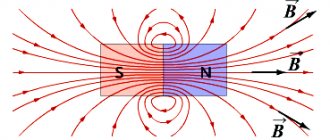
Now let's remember what the magnetic field lines of a permanent strip magnet look like. To do this, place small magnetic arrows around the magnet. They will instantly begin to move and arrange themselves in a strictly defined order.
From your eighth-grade physics course, you already know that the magnetic lines of a bar magnet come out of its north pole and enter its south pole. Moreover, they have neither beginning nor end: they are either closed or go to infinity, which is easy to verify with the help of iron filings.
It is not difficult to notice that the sawdust is arranged in the form of chains, with different densities around the magnet. This suggests that the effects that the magnet has on the sawdust are different at different points in the field. This effect is most pronounced near the poles of the magnet. And the further from the poles, the weaker this effect is, therefore, the weaker the magnetic field.
In physics, such a magnetic field is called inhomogeneous.
Its magnetic lines are curved, and its density varies from point to point.
An example of a non-uniform magnetic field is the field of a straight conductor carrying current.
In the figure you see schematic images of two sections of such conductors.
Let's remember that the circle in the center indicates the cross section of the conductor, the cross - that the current is directed away from us behind the drawing, and the dot - that the current is directed in the opposite direction, from behind the drawing towards us. This notation is called the arrow rule. The dot denotes the tip of an arrow flying in our direction, and the cross represents its tail, which could be seen if the arrow flew away from us.
Please note that direct current magnetic lines are concentric circles, the center of which is the current-carrying conductor itself. In those areas of space where the magnetic field is stronger, the magnetic lines appear closer to each other (that is, denser), and vice versa.
Thus, from the pattern of magnetic lines one can judge not only the direction of the magnetic field, but also its magnitude.
As for a uniform magnetic field, it makes sense to consider it only in some approximation. The fact is that a uniform magnetic field is a field in which at each point the force on the magnetic needle is the same in magnitude and direction.
Since magnetic field lines are always curved, the field is only approximately homogeneous. An example of a uniform magnetic field is the field inside a strip magnet near its middle.
Another example of a practically uniform field is the field that arises inside a solenoid if the length of the solenoid is much greater than its diameter. However, outside the coil with current, the field is non-uniform and its magnetic lines are located approximately the same as those of a strip magnet.
It can also be seen that the magnetic lines of a uniform magnetic field are parallel to each other and located with the same density.
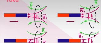
Let's consider another experiment. Let's place magnetic arrows around a current-carrying conductor in the shape of a coil. Having closed the circuit, we will see that the arrows in the magnetic field are located along the magnetic field lines, but they are oriented differently. This is explained by the fact that on the left side of the installation the current “comes out” of the sheet, and on the right side it “enters” it.
Based on the result of this experiment, we can say that the magnetic field lines have a certain direction, which is related to the direction of the current in the conductor.
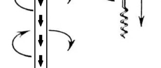
This relationship can be expressed using the gimlet rule (or the right screw rule). It is as follows: if you rotate the handle of a gimlet so that its tip moves in the direction of the current in the conductor, then the direction of rotation of the handle of the gimlet will indicate the direction of the magnetic field lines of the current.
The direction of the magnetic field lines can be determined in another way, for example, using the right hand rule: if you clasp the current-carrying conductor with the palm of your right hand so that the outstretched thumb is aligned with the current, then the bent four fingers will indicate the direction of the magnetic field lines.
A similar rule applies to determining the direction of the magnetic field inside the solenoid: if you clasp the solenoid with the palm of your right hand so that the bent four fingers indicate the direction of the current in the turns, then the thumb set back ninety degrees will indicate the direction of the magnetic field lines inside the solenoid.
And the last thing I would like to draw your attention to. To depict a uniform magnetic field perpendicular to the plane of the drawing, this technique is used. If the magnetic field lines are directed away from us beyond the drawing, then they are depicted with crosses.
And if they come to us because of the drawing, then dots. As in the case of current, the cross is like the plumage of an arrow flying away from us, visible to us, and the point is the tip of the arrow flying towards us.
Gimlet rule and right hand rule
You can remember how the direction of the current in a conductor and the direction of magnetic lines relate, or you can use a simple method - the gimlet rule.
If you screw in a gimlet (screw, corkscrew) with your right hand with the tip in the direction of the current, then your thumb will turn in the direction of the magnetic lines.
You may find another interpretation of this mnemonic rule more convenient to use - the right-hand rule (Figure 6).
If you wrap your right hand around a straight conductor carrying current with your thumb out so that it coincides with the direction of the current, then your four fingers will show the direction of the magnetic lines.
Figure 6. Right-hand rule for a straight current-carrying conductor
General rules
There are several options for specifying the direction of a perpendicular segment to two source vectors and defining the orientation of the basis. There are such important areas in physics:
- body rotations around the center of movement;
- force vector of the magnetic field at a selected point.
The choice of the path of the axial value is conditional, but it occurs in the same way, so the sign remains constant in the final value. Rules and methods help maintain a single choice:
- The gimlet rule. The wire is placed in the hand, with four fingers clenched into a fist. The main finger, which is located vertically, will show the path of movement of charged electrons (current). The remaining fingers, which are placed parallel to each other, will determine the direction of movement of the electromagnetic lines.
- Right hand rule. When placing the cable under test in your hand, the clenched fingers show the path of the force field lines, and the thumb shows the direction of the current. When the conductor moves forward along the lines that determine the tension, their movement is directed towards the palm. The thumb extended perpendicularly coincides with the movement of the rod. If you open your fist, your straight fingers will determine the course of the induction current.
- Left hand rule. The hand is positioned so that four fingers indicate the direction of electron movement. The path of the induction lines is directed into the palm. The bent finger shows the effect of force on the wire. The law acts to deflect a conductor rod, to the right and left of which magnets are located, and it is under current.
Using these rules, the direction of the vector product and bases (or one of two interrelated concepts) is selected. The technique is used to determine the directions of the main quantities instead of using other methods, if you have an idea of the order of the factors in the corresponding formulas.
Methods for choosing a rule are combined to calculate the positive path of the product of vectors and a basis (coordinate system) in space. A basis is defined as a coordinated vector set, with any vector in space represented in a single version of the linear relationship of vectors from this package.
Exercises
Exercise No. 1
Which pole will the magnetic needle turn towards the observer if the current in the conductor is directed from A to B (Figure 7)?
Will the answer change if the arrow is placed above the conductor? Figure 7. Magnetic needle located under the conductor
Using the knowledge gained, we can say that the magnetic needle pole towards us (Figure 8, a).
How did we determine this? If we draw a drawing (Figure 8, b) with point A towards us, then the current will flow from us. So we can, using the ready-made experimental results given above in this lesson, determine the direction of the magnetic field lines. The magnetic needle will turn its north pole in the direction of these lines, i.e. away from us.
Using the right-hand rule, we get the same result: if the thumb points in the direction of the current, then the four fingers point in the direction of the magnetic lines.
Figure 6. Orientation of a magnetic needle in a given direct current magnetic field
If we place the conductor under the magnetic needle, its position will change. It will turn its north pole towards us , because at this point the magnetic lines will also be directed towards us.
Exercise No. 2
There is a direct electrical wire located (walled up) in the wall.
How to find the location of the wire and the direction of the current in it without opening the wall? We can detect such a wire using a magnetic needle on a stand or a regular compass. When moving the compass along the wall (without turning it), you need to monitor the position of the magnetic needle. If it begins to deviate, it means that in this place it is affected by the magnetic field of a conductor with current - our wire is somewhere nearby.
To determine the direction of the current in this wire, let's look at where the north pole of the compass needle points. Its direction will coincide with the direction of the magnetic lines. If it turns to the right, then the current is directed upward, and if it turns to the left, then the current is directed downward.
Left hand rule
Among such methods, as a rule, the gimlet rule, the right and left hands, the left hand rule should be noted. In order for this rule to work, it is necessary to position the left palm in such a way that the direction of the four fingers is towards the electric current in the conductor. The induction lines enter the palm perpendicularly at an angle of 90 0. The thumb is bent and indicates the direction of the force acting on the conductor. Typically, this law is applied when it is necessary to determine the direction of deflection of a conductor. In this situation, a conductor is located between two magnets and an electric current is passed through it.
The left hand rule is also formulated in such a way that the four fingers on the left hand are located in the direction in which positive or negative particles of electric current move. The induction lines, as in other cases, should be perpendicular to the palm and enter into it. The protruding thumb indicates the direction of the Ampere or Lorentz force.
To determine the direction of voltage in a magnetic field, the gimlet rule is used. The method shows fairly accurate results if the field is located rectilinearly relative to the conductor through which an electric current is passed. To determine the characteristics of a force field with a magnetic moment, the left and right hand rule is additionally applied.