People who have electric stoves that have served for decades are often interested in connection diagrams for the burners. This is not surprising, because over time these elements fail, and the only way to fix everything is to install new burners.
In theory, under ideal operating conditions, burners can last almost forever, but this, of course, does not happen. The fact is that we often forget to turn them off, which causes the heating elements to heat up to unimaginable temperatures. In some cases, you can even see cracks on the surface of burnt-out burners. But this only applies to older models; this does not happen with new ones.
When a stove burner burns out, the owner has to think about connecting a new element. It goes without saying that you can’t do without a diagram. Of course, it should be in the technical data sheet of the product. But we must admit that after 20 years, documents are lost or become unreadable.
Attention! Ideally, you should connect the new burner to the electric stove exactly according to the diagram indicated in the technical data sheet.
Connection diagrams for popular stoves
Dream 8
This is one of the best selling slabs of the past. It’s not surprising that you can see it in many people’s kitchens. It consists of the following key nodes:
- Heating element E1+ E2,
- Heating element E3-E5,
- S1-S4,
- F,
- indicators.
Heating elements E1-2 are located in burners 1 and 2, respectively. This can be easily seen in the diagram in the technical documentation of the stove. TEN E3-E5 is an oven. S1-S4 are a switching unit with which you can control the electric stove.
The indicators available in the electric stove, according to the diagram, are of two types HL1 and HL. They are responsible for the operation of heating elements. Also available HL3. But this is just illumination of the oven, so that you can always see the condition of the dish.
Attention! Most designs use a T-300 thermal relay. Moreover, the power of each heating element is 1 kW.
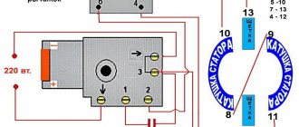
Switch S1 is responsible for adjusting the degree of heating. It has four positions with which you can provide different intensity of fire. In the first position, P1-2 and P2-3 are closed.
When this happens, heating element E3 is activated. In this case, the current will travel the following route:
- it all starts with contact XP,
- then comes relay F,
- P1-2,
- E4-5 + E3,
- P2-3.
The first destination is the plug pin. This heating element is connected in series to the fourth heating element and to the fifth. Moreover, it is connected in parallel to the second and third. You can easily verify all this for yourself by looking at the diagram below.
When switching to position number two occurs, P1-1 and P2-3 are activated. Naturally, the circuit through which the current passes changes. It all starts with the plug contact located at the bottom, which is labeled as XP. Then the following intermediate points follow:
- F,
- P1-1,
- E3,
- P2-3.
It all ends with the XP plug on top. When this circuit is activated, exclusively heating element E3 is started. An increase in power can be achieved by reducing resistance. The main advantage of this scheme for connecting an electric stove burner is that it is possible with a constant mains voltage, which is 220 V.
For S1 there is position number 3. In this case, P1-1 and P2-2 are closed. Because of this, the E4+5 heating elements are connected. If we talk about S4, then this switch is responsible for the operation of the lamp. On the standard diagram of the operation of electric stove burners, it is designated HL3.
Electra 1002
The second, most frequently used electric stove in homes and apartments is Electra 1002. Therefore, knowing about its burner connection diagram is simply necessary. Fortunately, it is not particularly difficult and even a beginner can figure it out.
So, the electric stove has four burners; naturally, each of them has its own connection diagram. The first two heating elements are indexed H1 and H2. Their main difference is their tubular structure.
The third burner in the electric stove connection diagram has the index H3. It is made of cast iron and is quite large - 200 mm. H4 is also made from cast iron. Its size is 145 mm.
Regulators P1 and P2 are responsible for adjusting the temperature. They do not have power levels as such. But this drawback is more than compensated for by the seven-speed switches P3 and P4. In turn, the PSh is responsible for the oven and has 3 positions.
Switch P5 is responsible for blocking. The signal lamps for the burners in the electric stove circuit are L1-4. The fifth L allows you to illuminate the oven. Also available L6. It turns on when the appropriate temperature is reached in the cabinet.
Elements H5-6 are respectively responsible for heating the oven. Seven is a grill. The thermostat is designated by the simple letter T. There is also a key switch - this is B. The seventh L illuminates the oven.
Attention! The gearmotor is designated as a capital letter M.
Schemes for other popular models
Of course, electric stoves Electra 1002 and Dream 8 were one of the most popular in their time. But now people prefer to buy products from completely different brands; among the most famous are Gorenje and Hansa. It is their stoves that most people install in their kitchens.
You can also remember the Lysva brand. Of course, few people now buy their stoves if they have the opportunity to purchase products from a more respectable brand, however, the company has a fairly large circle of consumers. In general, below you will find wiring diagrams for electric stove burners from the most popular brands.
With this diagram for connecting electric stove burners, you can easily do all the work yourself. But for their high-quality implementation, at least basic knowledge of the operation of electrical networks and electrical appliances will not interfere.
Socket for oven and hob
Electric hobs and ovens consume a lot of power (from 2.5 to 10 kW). Therefore, according to modern electrical safety rules, an oven socket requires a separate dedicated power line from the panel.
Moreover, if the hob and oven provide for independent installation, then they will require two sockets, with separate connection points on the distribution panel.
Many people have a question: is it possible to connect an electric oven from an existing regular outlet that was previously installed in the kitchen for a kettle, microwave, etc.?
- It is possible, the main thing is that 3 conditions are met:
- the oven must have a power of no more than 3.5 kW;
- the socket is connected with a three-core copper cable from the panel with a cross-section of at least 2.5 mm2;
- in the electrical panel, replace a conventional circuit breaker with a thermal release with a differential circuit breaker with a rated current of no more than 16 A.
According to the third condition, some may experience inconvenience and minor problems. As a rule, many people still have one 16 A - 25 A circuit breaker for the entire socket group, plus one more for lighting.
If you replace the only circuit breaker for sockets with a differential 16 A and connect the oven through it, it will be practically impossible to use other electrical appliances while the oven is working and food is being prepared.
Here you will have to make your own choice, either in favor of saving (not installing new wiring, a separate outlet, etc.), or in favor of comfort and convenience. It is not recommended to leave a regular modular machine in the panel without protection against leakage currents when connecting the oven to an old outlet.
The installation height of the new socket under the oven should be no more than 90 cm from the floor. Although it is also often placed at the level of the kitchen legs.
The most important thing here is ease of use. For safety reasons, when wet cleaning and wiping the oven with a wet cloth, it must be disconnected from the power supply.
And crawling under the very bottom of the kitchen every time to pull out the plug is not always convenient. In addition, here you need to take into account possible situations such as water leaks and kitchen flooding. Therefore, the socket should still be raised 5-10 cm above the floor.
The main requirement for placing the outlet is not to place it directly behind the oven. You can install it on the left, on the right, or as mentioned above - under it, directly near the floor.
When you have decided on the location of the outlet, you need to connect it.
Connect the phase and neutral cores of the cable to the outermost contacts of the socket
In this case, it does not matter at all where the phase will be located, and where the zero is - on the right or on the left. Connect the grounding conductor (yellow-green) to the grounding terminal (usually the middle one)
Replace the frame or decorative cover.
Wiring Requirements
Particular attention should be paid to the quality of electrical wiring, on which the safety and correct functioning of the entire system depend.
The following factors are taken into account: The oven and hob are connected via grounding. The plug or socket for the oven must have 3 or 5 contacts (in the first case for a 220 Volt network, in the second - for 380 Volts)
In the tasks of the old building, this condition was not always adhered to. However, modern requirements are different, so a new cable will be required. Electrical wiring is connected to the distribution box only through an RCD (residual current device). Low-power equipment (up to 2.5 kilowatts) is connected to the existing electrical network (if it meets modern requirements). To connect powerful equipment you will need a dedicated line.
The optimal cable cross-section is 6 square millimeters. A wire with this cross-section will withstand a long-term load of 10 kilowatts. The recommended protection class for the machine is C32. If the panel power does not exceed 8 kilowatts, a cable with a cross-section of 4 millimeters and a circuit breaker with protection class C25 will be sufficient.
The correct choice of cable is VVGng or NYM. When purchasing a cable, take into account the diameter of the conductor. For a wire with a cross-section of 4 millimeters, the diameter will be 2.26 millimeters, and for a 6 mm conductor - 2.76 millimeters.
The data for the residual current device is one point higher than the rating of the circuit breaker. For a 32 Ampere device you will need a 40 Ampere RCD.
The nuances of connecting the heating element and checking it
The heating element ensures normal operation of the electric stove burner. In fact, this is its main element, without which the normal functioning of the entire circuit is impossible. But for everything to go smoothly, it is necessary to take into account many nuances. Among the main ones:
- The contact connections should not touch the body of the electric stove, otherwise the connection may end disastrously.
- The contacts must be properly insulated. Cambric is best suited for this purpose. As a last resort, you can use regular electrical tape. But its reliability is much worse.
- It is very important to test the heating element of the electric stove burner so that the connection according to the diagram is successful.
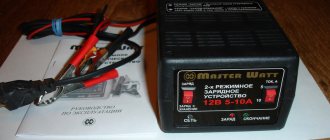
To test the heating element of an electric stove burner you will need a special device. It's called an ohmmeter. A multimeter is also quite suitable for this purpose. These devices are designed to measure resistance in a circuit.
If you are using a multimeter, then first you need to set the appropriate measurement mode. Next, the two wires must be connected to the corresponding sockets.
After this, you need to turn on the device. Using two probes you can measure the resistance of heating elements. To do this, you need to use probes to connect the electric stove burner to the contacts of the heating element.
If your measuring device is a digital multimeter, then after connecting its probes to the contacts, the display will immediately show the result. Three positions are possible:
- gap,
- complete unsuitability
- resistance.
Of course, in order to connect the heating element of the burner to the electric stove according to the diagram, it is necessary for the multimeter to show the third position. Otherwise, nothing will work.
After connecting the heating element of an electric stove, each person has a question: will the burner work after this? Are all wires connected correctly? This is especially true when it comes to burners.
Attention! Diagnostics of the connection of all wires of the heating element to the general circuit of the electric stove should be carried out in a passive state.
For diagnostics you will need the same device. Before testing, the load of the electric stove is turned off, the power switch is turned on and the probes are connected to the plug. The display will show the corresponding result.
We carry out grounding
The need for grounding is explained by the high power of kitchen electrical appliances.
Its implementation is possible, firstly, by using the existing general grounding of the dwelling structure. For this purpose, you should contact the Housing Office to confirm information about connecting the distribution panel of your own square meters to the house grounding. When confirming this information, the earth electrical wire must be connected to the grounding of the distribution board, which is the thickest electrical wire, which in turn is connected to the panel housing with a bolt.
If there is no house grounding in your own home or if the apartment is located on the ground floor, grounding can be equipped independently. To do this, three rods are driven into the ground, connected by a metal strip to which a steel wire is attached. Its installation is carried out in the house, where the earth's electrical wire is connected.
Connection types
There are several ways to connect the stove to electricity: directly to the panel, through a terminal box, or using a socket and plug.
Connection via terminal box
Connecting the stove via a terminal box is a widespread option. The point at which the connection is made can be hidden in the wall or installed externally. The box is placed a couple of meters from the stove, and the distance from the floor should be more than sixty centimeters.
Connection via socket
The third type of connection to the network is the use of a grounded outlet. It is not recommended to install ordinary sockets, because they are not designed for such powerful electrical appliances, which means they will constantly fail.
There are three types of power outlets:
domestic ones, the grounding of which is located at the top at an angle of 90° relative to zero and phase;
Belarusian, in which the contacts are at an angle of 120° relative to each other;
European, the grounding contact of which is flat and placed at the bottom.
How to connect an electric stove to a 220 V network
All the above diagrams were specifically for a single-phase 220 V network. To connect, you will need a three-wire cable, a three-pin power socket and a plug with a rated current of at least 32 A. Let’s say right away that connecting equipment from different brands is fundamentally no different
It doesn’t matter which stove you purchased - Electrolux, Gorenje, Bosh, Beko. Doesn't matter
The only difference is the different design of the covers that cover the terminal box on the housing and different methods of fastening it. Everything else is the same.
Connecting the cable to the electric stove
First, the cable selected for connection must be connected to the electric stove. On the rear panel, usually at the bottom left there is a terminal block to which the conductors are routed.
The terminal block to which the electrical cord must be connected
Nearby are connection diagrams for different networks.
Schematic illustration of connections for different networks
With a 220 V network, the diagram is on the far right. On the plate, contacts 1,2,3 should be connected by one jumper - this will be the phase (red or brown conductors), the second - contacts 4 and 5 - this is neutral or zero (blue or blue), the sixth contact is ground (green or yellow -green). Electrical plates usually come from the store with jumpers already installed, but it doesn’t hurt to check.
Connecting the cable to the electric stove
It is more correct and reliable to crimp the conductors with contact plates, and then connect them. This connection is more reliable, but often the conductors are simply twisted around the clamping screw and then tightened. In any case, it is better to follow the color coding - this way there is less chance of making a mistake.
It is better to terminate the conductors with contact plates
Plug installation
Next, a plug is connected to the cable. The power plug is collapsible. Unscrew the two mounting screws and remove the cover with contacts. The fixing bar holding the cable is also removed. The protective insulation is removed from the edge of the flexible cable (about 5-6 cm), the conductors are straightened, their ends are also stripped of insulation by about 1.5-2 cm. The cut end of the cable is inserted into the plug body.
This is what the plug for connecting an electric stove looks like
The clamping screws on the contacts are loosened, the conductors, if they are multi-core, are twisted into a bundle. These flagella are twisted around the contacts and tightened with clamping screws.
The distribution of conductors matters and they must be connected carefully. The top contact of the plug is usually labeled - the “ground” wire (green) is connected here. When connecting a socket, you need to apply ground to a similar connector.
Connecting the wire to the electric stove
The other two contacts are “phase” and “zero”
Where to apply which one is not important, but when connecting the socket, the “phase” must fall on the “phase”, the “zero” must fall on the “zero”. Otherwise there will be a short circuit
So before turning it on, be sure to double-check that the wires (phase and neutral) are screwed in correctly.
How to determine the phase in an installed socket
If you already had an electric stove before, and there is a socket, you need to find in it where the grounding, phase and neutral are located and connect the wires in the plug accordingly. The easiest way to determine this is to use a voltage indicator in the form of a screwdriver. It works simply - install the indicator in the place of the expected phase, and look at the LED mounted in the housing. If it lights up, then there is voltage and this is a phase. If there is no voltage, the LED does not light up, and this is zero.
The ground is even easier to determine: is the contact at the top or bottom.
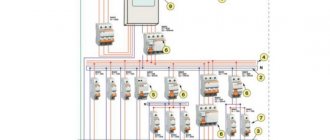
Electrical parameters and ratings of circuit breakers
As we found out, there should be separate RCDs and a circuit breaker in the electrical panel. Through them the phase is supplied to the socket. This pair can be replaced with a difavtomat. These are the same two devices, but in one case. The negative is taken from the common bus, passes through the RCD, and the grounding is taken from the corresponding bus.
The rating of the machine is selected based on the maximum current consumption. This data is in the electric stove's passport and is usually in the range of 40-50 A. In this range, the ratings come in large increments - 40 A, 50 A, 63 A. It is better to choose the nearest larger one - this way there is less chance of a false shutdown when operating at full power . That is, if the declared maximum current consumption is 42-43 A, still take a 50 A machine.
On the other hand, you may never turn on all the burners and oven, and even at full power, and more powerful machines are significantly more expensive. It's up to you to choose.
The rating of the RCD is taken one step higher than that of the machine. If you decide to install a 50 A machine, then the RCD is required at 63 A, the leakage current is 30 mA.
Algorithm for connecting a combined stove in an apartment
If you previously had an electric stove, you will initially need to conclude an agreement for the supply of gas. To do this, you must provide the following documents to the gas service:
- proof of ownership;
- registration certificate for residential premises (apartment);
- certificate of family composition;
- maintenance contract;
- gas meter passport;
- subscriber book.
However, connecting the stove to the gas pipeline yourself is prohibited by law.
If the gas service notices this violation during an inspection, it will impose a fine and may terminate the gas supply contract. However, you can connect the stove to the gas mains and the electrical network, but not turn it on, but call a specialist who will check all connections and give the go-ahead for connection. This method allows you to save money on services from Gorgaz, but without skills in such work or with a careless approach to this matter, it is better not to get involved.
If you decide to make the connection yourself, then it is better not to deviate from the following algorithm of actions:
- Draw a power line and install a grounded socket near the intended location of the stove.
- Place the stove on a flat surface or adjust the height of the legs using a level. A slanted surface will prevent food from cooking evenly.
- The thread of the flexible hose is wrapped with FUM tape, after which it is connected to the gas pipe and tightened with a wrench.
- The hose is connected to the device in the same way.
- Connecting the device to the power supply. Electricians advise not to do this directly, but only through an outlet.
- Check the tightness of the connections with a thick soapy solution under the supervision of a specialist, thereby making your independent connection legal.
- Check the functionality of the burners and oven.
Connecting any gas equipment yourself is not a safe matter, so it is very important to treat this matter with the utmost care, without neglecting to check each connection. Saving five minutes can be very costly in the future.