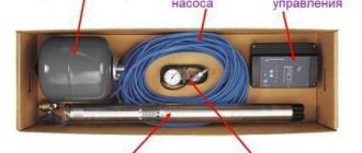
Operating principle and main components
Lead-acid batteries are charged with constant (rectified) voltage, stable in level. To get current flowing into the battery, the charging voltage must be higher than the battery voltage. The charge current in this mode depends on the difference in voltage between the source and the battery.
A completely discharged car battery produces a voltage of 10.5 volts (it cannot be discharged below), a fully charged one produces 12.6 volts. During the process, the level at the output of the charger remains constant, and at the battery terminals it gradually increases. Therefore, at the beginning of charging the current will be maximum, at the end - minimum. A decrease in the current level serves as a sign of the end of the process. Also, to automatically complete charging, you can use the voltage on the battery to reach 12.5..12.6 volts.
The process of charging a lead-acid battery with a stable voltage.
The standard charger construction diagram contains:
- Network transformer;
- Rectifier;
- Current (voltage) regulator - stabilized or not.
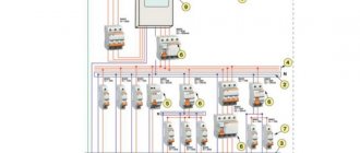
General scheme for constructing chargers for car batteries.
Instruments that indicate current and voltage are highly desirable. Additionally, the memory can be equipped with:
- current limiting circuit;
- electrical protections;
- indication or automatic shutdown at the end of charging.
These functions are service functions and increase the convenience of working with the memory.
Schematic and printed circuit board of the SCR memory
The printed circuit board is drawn by hand with a marker. You can make the wiring yourself, for example based on this picture:
Schematic diagrams of chargers
A charger for a car battery can be made using different element bases. It all depends on the availability of components and the qualifications of the technician.
A simple 12V car battery charger
To regulate current and voltage, you can use a regular potentiometer. By rotating its engine, you can adjust the current in the charging circuit.
Memory with adjustable potentiometer.
In practice, such a scheme is not used for two reasons:
- the full load current flows through the potentiometer; it is difficult to find an element of such power;
- The load current flows through the moving contact of the variable resistor motor, this significantly reduces the reliability of the device.
But using this diagram it is easy to understand the principle of operation of simple chargers.
Scheme of a simple memory.
In practice, a different charger circuit is implemented for DIY assembly. Here the potentiometer is connected to the base circuit of the transistor, and the current through it is small. The charging current goes through the collector-emitter of the transistor, and a semiconductor element of similar power is much easier to find. But this is the main drawback of the scheme . The through current flows through the regulating element, all excess power is dissipated on it. A large radiator will be required.
For normal operation of such a charger, it must be supplied with increased voltage - at least 18 volts - in order to provide a margin for adjustment. In accordance with this requirement, you must select a network transformer.
Thyristor charger ku202n
A popular scheme is a homemade charger, where the battery is charged with rectified voltage, and the current is manually regulated using a thyristor (domestic KU202N or foreign analogues are suitable).
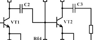
Circuit diagram of a thyristor charger.
The mains voltage is reduced by transformer T1 and rectified by bridge VD1..VD4. A pulse generator is assembled on a unijunction transistor VT2. Its frequency is set by a circuit of capacitor C1 and a controlled resistor on VT1. Its resistance is adjusted by potentiometer R5. At the beginning of each half-cycle, the generator is started through the R1VD1 circuit and begins to produce pulses at a given frequency. The first pulse opens the thyristor, the rest (the next ones until the end of the half-cycle) do not matter. The earlier the key on VS1 opens, the larger part of the sine wave enters the load, the higher the average voltage on the battery and the average current flowing into it.
The principle of phase-pulse regulation.
An ammeter is used to monitor this current. The disadvantage of the circuit is that the voltage is not stabilized and will change following changes in the 220 volt network voltage (it can vary within ±5%). Following the voltage, the charge current will change, so the process requires periodic monitoring and, if necessary, adjustment. In addition, the voltage on the battery cannot be measured with a conventional voltmeter or multimeter - they are designed to measure constant voltage, and the charger produces a form that is sharply different from constant voltage. The error will be very high, so to control it you will have to disconnect the battery and measure its voltage.
Filter capacitors cannot be installed after the rectifier - the circuit only works with rectified, but not with constant, input voltage.
Memory circuit without a unijunction transistor.
If there is no unijunction transistor, the circuit can be assembled without it. It will get a little more complicated. But instead of an adjustable resistance on the transistor, it is possible to use a conventional potentiometer to set the generation frequency.
Triac charger.
There are various variants of this scheme. For example, an adjustable device based on a triac. Here the power switch is a powerful triac, and the thyristor is involved in the circuit for generating opening pulses.
Video version: Charger with desulfation on one thyristor.
Charger for car battery on tl494
The charger can be built on a TL494 chip. This microcircuit is not used in a completely standard way - usually it is used to build fully switching power supplies with rectification of the mains voltage and “cutting” high-frequency pulses from the resulting constant (as in computer power supplies). There is also a network transformer and a secondary voltage rectifier. Only the adjustable stabilizer is pulsed. Its advantage is that the control element (transistor) opens for certain periods of time, no through current (equal to the load current) flows through it, so the size of the heat sink can be significantly reduced.
Memory circuit for TL494.
The microcircuit generates pulses, the frequency of which is set by the R4C3 circuit, and the width depends on the difference between the levels at inputs 1 and 2. The pulses control the transistor VT1, which, when opening, energizes the inductor L1. The stored energy is consumed in the load. The greater the load, the faster the reserve is consumed, the faster the output voltage drops, which leads to an increase in the duration of the pulses from output 8 of the microcircuit. Rotation of potentiometer R9 also leads to this - this is how the output voltage is regulated.
The charging current is regulated by the voltage difference between the battery and the charger output, but the TL494 chip allows for additional current limitation. For this purpose, a second error amplifier is used. The limiter current is set by potentiometer R3, and the actual current is measured as the voltage drop across shunt R11. If the current is higher than the set one, the pulse duration is reduced, and the output voltage is reduced until the required current is reached. This mode is useful when charging heavily discharged batteries, and also allows for stabilized current charging mode . Together with a wide range of voltage regulation, the ability to limit current makes the charger universal and allows you to charge batteries made using various technologies. The limiter also protects power elements from overcurrent.
The part values are indicated in the diagram. It is better to make the choke on an alsifer core.
The core must have an air gap of 0.15..1 mm.
When setting up, the number of turns is selected so that the whistling of the winding is observed only at an average load current, and disappears when it increases. If the whistle disappears early (at low currents) and the output transistor gets hot, the number of turns must be increased. You need to focus on 20..100 turns of wire with a diameter of 2 mm. Also, when assembling, you need to add a voltmeter and an ammeter (can be digital or pointer) to the electrical circuit - it will be much more convenient to use. The output voltage is smoothed by capacitor C6, its shape is close to constant.
We recommend: How to make a charger from a computer power supply
Auto-shutdown circuit
It is convenient for the battery to turn off at the end of the energy replenishment process. One of the options for such an automation scheme is shown in the figure.
Automatic shutdown circuit.
The operating principle is based on monitoring the voltage of the battery being charged. As soon as it reaches the nominal level (it is adjusted by a potentiometer), the transistor will open, the relay will operate and turn off the voltage from the battery. The LED will light up to indicate the end of charging. Any relay can be used with an operating voltage of 12 volts and a contact current of at least 15 ADC.
The advantage of the circuit is that it can be assembled on a separate board and used in conjunction with any ready-made charger. The disadvantage is the need to measure the voltage directly at the battery terminal, so the measurement circuit (highlighted in red) must be made with a separate wire with a clamp and connected directly to the positive terminal of the battery.
Circuits with charging current control, which turn off the charger when the current drops below a set limit, are free from this drawback. To measure current, a measuring resistance (shunt) must be installed in the charger.
Circuit of a powerful charger with current regulation
Scheme of a powerful charger.
Another memory circuit that provides a current of at least 10 A is worthy of attention. Its features:
- the control circuit is assembled on the 220 volt side;
- The primary winding of the transformer simultaneously serves as an inductance that accumulates energy and then transfers it to the load through the secondary windings.
The regulation principle is phase-pulse, the key is triac VS1. The current is set by potentiometer R1 and is adjustable from zero to 10 A. The primary winding of the transformer must have sufficient inductance. For its manufacture, you can use LATR-2. Its winding will serve as the primary. You need to install insulation on top (3 layers of varnished fabric is enough), and wind the secondary winding on top with a wire with a cross-section of 3 sq. mm, 40+40 turns. Resistor R6 serves as a rectifier load and creates battery discharge pulses. It is believed that this mode extends the service life of the battery. Instead, you can install a 12 volt car incandescent lamp with a power of 10 watts.
Thyristor control, principle of operation
A thyristor is a device with the properties of a semiconductor, the design of which is based on a monocrystalline semiconductor having three or more pn junctions.
Its operation implies the presence of two stable phases:
- “closed” (conductivity level is low);
- “open” (conductivity level is high).
Thyristors are devices that perform the functions of power electronic switches. Another name for them is single-operation thyristors. This device allows you to regulate the impact of powerful loads through minor impulses.
According to the current-voltage characteristic of the thyristor, an increase in the current in it will provoke a decrease in voltage, that is, a negative differential resistance will appear.
In addition, these semiconductor devices can connect circuits with voltages up to 5000 Volts and currents up to 5000 Amps (at a frequency of no more than 1000 Hz).
Thyristors with two and three terminals are suitable for operation with both direct and alternating current. Most often, the principle of their operation is compared with the operation of a rectifying diode and it is believed that they are a full-fledged analogue of a rectifier, in some sense even more effective.
The types of thyristors differ from each other:
- Control method.
- Conductivity (unilateral or bilateral).
General management principles
The thyristor structure has 4 semiconductor layers in series connection (pnpn). The contact connected to the outer p-layer is the anode, and the contact connected to the outer n-layer is the cathode. As a result, with a standard assembly, a thyristor can have a maximum of two control electrodes, which are attached to the internal layers. According to the connected layer, the conductors are divided into cathode and anode based on the type of control. The first type is most often used.
The current in thyristors flows towards the cathode (from the anode), so the connection to the current source is made between the anode and the positive terminal, as well as between the cathode and the negative terminal.
Thyristors with a control electrode can be:
- Lockable;
- Unlockable.
An indicative property of non-locking devices is their lack of response to a signal from the control electrode. The only way to close them is to reduce the level of current flowing through them so that it is inferior to the holding current.
When controlling a thyristor, some points should be taken into account. A device of this type changes operating phases from “off” to “on” and back in jumps and only under the condition of external influence: using current (voltage manipulation) or photons (in cases with a photothyristor).
Assembly technology
Most electronic components are best assembled on a printed circuit board. At home, the board can be made using the LUT method or the photo method. You can develop a drawing in free programs, such as LayOut or the shareware Eagle. Or you can draw in the old-fashioned way on paper and apply the design with varnish to the surface of the foil. The board is etched in a solution of ferric chloride or in the following composition:
- 100 ml pharmacy hydrogen peroxide.
- 30 g citric acid.
- Two teaspoons of table salt.
Power elements are mounted on radiators of sufficient area. They must be installed on heat-conducting paste. If the heat-removing surface of the element is not connected to the common terminal, the part is attached to the heat sink through an insulating gasket - mica or made of elastic material. The radiator can be the metal wall of the housing. You can also make the heat sink part of the design. You can organize radiator airflow - then their area can be significantly reduced. To do this, you will need a 12-volt fan, which can be connected to the output of the diode bridge.
The body can be selected ready-made or made independently. Mounted on the front panel:
- measuring instruments;
- voltage and current regulators;
- On indicators.
It is better not to use terminals and connectors to connect the wires going to the battery. The currents flow through them are large, so a potential source of additional transition resistance is undesirable. It is better to solder the wires to the board and route them through the holes in the front panel. The cross-section of the conductors should be sufficient - at least 2 sq. mm, and preferably 4 sq. mm. On the other side of the wires you need to solder alligator clips.
Charger in a homemade case.
This is not a complete overview of charging circuits for a car battery - there are a great many of them. Based on the presented designs, you can understand the principles of construction of the memory, the requirements for them, and understand the simple circuitry. Having worked out the assembly of these chargers in practice, you can later move on to more serious circuits, including the use of microcontrollers.
Related article: Homemade charger for lithium-ion batteries
Power regulator
The circuit implements the principle of pulse-frequency regulation of the firing angle of thyristors due to synchronization with the network. Such control is the most effective and reliable, since the thyristor operates in normal modes without overestimating its capabilities.
The circuit contains a generator that generates control pulses and shifts them relative to the pulse edges when the mains voltage passes through zero. The control sequence of pulses is supplied to the UE and K. The voltage in the load is rectified using a full-wave rectifier. The use of containers in the circuit as filters is unacceptable, since they will violate the main principle of operation of the device. Such a power regulator can be used to control the temperature of a soldering iron tip by changing its supply voltage. But if you need to organize control of the primary circuits of the transformer, you will have to turn on the load in front of the diode bridge. The regulation current should be no more than 7.5 A.
Answers to 5 Frequently Asked Questions
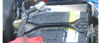
Will I need to take any additional measures before charging the battery in my car? – Yes, you will need to clean the terminals, since acid deposits appear on them during operation. The contacts need to be cleaned very well so that current flows to the battery without difficulty. Sometimes motorists use grease to treat terminals; this should also be removed.
How to wipe charger terminals? — You can buy a specialized product in a store or prepare it yourself. Water and soda are used as a self-made solution. The components are mixed and stirred. This is an excellent option for treating all surfaces. When the acid comes into contact with soda, a reaction will occur and the motorist will definitely notice it. This area will need to be thoroughly wiped to get rid of all the acid.
If the terminals were previously treated with grease, it can be removed with any clean rag.
If there are covers on the battery, do they need to be opened before charging? — If there are covers on the body, they must be removed.
Why is it necessary to unscrew the battery caps? — This is necessary so that the gases formed during the charging process can freely exit the case.
Is there a need to pay attention to the electrolyte level in the battery? - This is done without fail. If the level is lower than required, then you need to add distilled water inside the battery
Determining the level is not difficult - the plates must be completely covered with liquid.