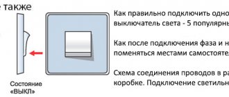
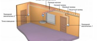
The connection diagram for a light switch with one key will allow you to accurately cope with this process. In fact, a switch is a primitive device that is located on the ceiling and connected to the electrical wiring. The products differ in shape and design, but they all have the same internal layout.
Today we will look at the process of connecting a single-key device if repair or replacement is necessary. In order to avoid any questions, we have to study several installation methods.
Wiring diagram for a light switch with one key
What is a switch and what is it for?
A switch is a simple device that can be either mechanical or electronic. The device is required to close and open an electrical circuit. This means that it turns the lamp on and off.
In this case, we will look at the configurations and installation features of the most primitive, single-key switches. Such structures consist of the following:
- main unit - metal base with contacts for connection and a digger;
- fastening elements - metal tendrils that are connected to each other by plates;
- external casing - panels made of plastic or other material;
- moving part - keys.
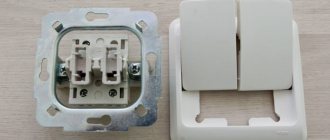
The internal elements, at least most of them, are made of metal, most often galvanized. The outer panel is made of safe plastic. However, on sale you can find ceramic structures that can withstand a load of more than 30 A, while plastic can withstand a load of no more than 16 A.
Ceramic socket and switch
It is worth highlighting the following reasons why there is a need to install a single-key switch:
- If a lamp with one lamp is located at a distance from other light sources.
- Such switches are often used to control a separate line. For example, such lighting is mounted above a table in the kitchen.
- Hanging lamps and miniature sconces, regardless of configuration, are connected to single-key devices.
- The main reason for installing a switch is the violation of the integrity of the body of the old device, which creates a danger of electric shock. In addition, sometimes internal structural elements fail.
Installing a line above a table in the kitchen
The design of the switch on the external and internal sides differs due to functional features and degree of load. So, in some models LED backlighting is installed as an addition.
The structure of the switch: 1 is a key with which the light is turned on and off; 2 – outer frame – decorative element; 3 – the main working unit, thanks to which the device functions
The installation of such a device will be relevant for any type of room where there are lamps without a power cable (in the case of table lamps and floor lamps it is not installed). This connection is typical for bulky chandeliers.
When choosing designs for rooms with high levels of moisture, and in particular for the bathroom, you need to pay attention to the marking of the degree of protection - IP. So, a device suitable for the bathroom is IP-40. If the switch is installed outdoors, it is recommended to purchase the IP-55 model.
When purchasing, pay attention to the IP marking
How to connect a two-key switch to a two-wire wire
Connecting a two-key switch to two light bulbs is quite simple, the main thing is to accurately observe the order of all connections. The two-key switch has terminals for a three-wire wire, while the light bulbs require a regular two-wire cable. When using a standard junction box, it will easily accommodate the necessary connection assembly that will be required for this connection.
Connection diagram
If you have two lamps in different rooms or one chandelier with two bulbs, it will be convenient to use a double switch. Such a switch has three contacts and two jumpers, which are controlled by keys. Another necessary element is a power supply with a two-wire cable, one wire (usually blue) is connected to neutral, and the second (brown or gray) to phase.
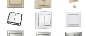
Types of switches for home use
Each manufacturer produces different models of switches, which differ both in shape and internal structure. However, several main types should be distinguished.
Table 1. Types of switches by switching principle
| View | Description |
| Mechanical | Devices that are easy to install. Instead of the usual button, some models have a lever or cord. |
| Sensory | The device works at the touch of your hand, and you do not need to press a key. |
| With remote control | This design is equipped with a special remote control, which comes included, or a sensor that responds to movements around. |
The most popular is the first option, which is installed everywhere. Moreover, such switches have become in demand since the very beginning of the appearance of the electrical circuit. The second option is less popular, especially in our country. The third option is a modern model, which is gradually displacing outdated switches from the market.
Installing a motion sensor in a structure is advisable both from the point of view of energy savings and home safety. For example, if you install a structure at the entrance, residents will notice if intruders break into the apartment.
Switch with additional lighting
Depending on their design features, there are devices with one or several buttons (on average, for standard electrical appliances, switches with two or three buttons are used). Each button is responsible for turning on and off a separate circuit.
So, if several lamps are installed in one room at once: the main chandelier, spotlights, sconces, then it would be advisable to install a design with three buttons.
In addition, no less popular are devices with two buttons, which are installed in all apartments without exception. Most often they are needed for a chandelier when there are many light bulbs.
Find a more detailed diagram of connecting a chandelier to a two-key switch in a special article.
Depending on the installation method, there are internal and external switches. The first option is installed in the apartment, because such structures look aesthetically pleasing. For safety during installation, a special box is installed, which is called a socket box.
Connection diagram
Built-in switches are used when there is electrical wiring hidden in the wall. Overhead devices are mounted in the presence of external conductors. In this case, the connection diagram has no fundamental differences.
Where is the switch installed?
Method number 1. Two-key switch
This method allows you to obtain pass-through switches from conventional two-key models. This is especially convenient if you don't want to spend time making complex changes to their design or don't have the appropriate tools.
Rice. 2. Two-key model of pass-through switch
To implement this model of a pass-through switch, you will need two two-key devices, connecting wires and a lighting source.
Once you have collected everything you need, follow these steps:
- Turn off the voltage on the panel using a circuit breaker - this will prevent electric shock during installation work. It will be more reliable if you simultaneously disconnect both the neutral and phase conductors for the corresponding lamp.
- Connect the first of the two-gang switches to the phase wire of the three-core cable. To do this, release the terminal on the switch and insert the core there. The core is clamped until reliable contact is obtained with minimal resistance to electric current.
- Also connect a wire to each of the output contacts. Next, lead them to the output contacts of the second two-key switch.
- From the input terminal of the second switch, take the wire to the lighting device.
If the lighting system is carried out as part of a major overhaul and replacement of all lamps and appliances in the house, then the walls are tapped for power distribution. Otherwise, you can get by with external installation in the cable channel. In case of a long distance between switching points, it is better to carry out wiring with a three-core cable. Since three wires are optimally used for intermediate connection of wires.
It should be noted that the above method works by simultaneously switching two keys at once, so each time you need to operate two buttons at once, moving them to opposite positions.
Otherwise, the logic of the circuit will be broken and next time you simply will not be able to turn off the light bulb. Therefore, if other household members may be negligent about such switches, it is better to redesign the device to a single-key version.
Installation of switches with one button
We will look at the basic connection diagrams for devices that have a similar structure (one button), but differ in the installation method. However, all these devices operate on the principle that a phase is started as a result of opening using a dynamic element. If you confuse the phase and zero contacts, there is a danger to life.
Switches with one button are often adjacent to sockets - this is convenient for bedside lamps
What equipment and materials will be needed during the work process?
In order to make the connection, you will need the following tools:
- stripping knife;
- screwdriver;
- indicator screwdriver;
- pliers;
- building level;
- electric drill;
- marker.
Indicator screwdriver
In addition, you will need the following materials:
- conductors of optimal length;
- wiring distribution box;
- clamps and electrical tape;
- corrugation;
- single-key switch. The simplest single-key switch - only two terminal contacts, at the input and at the output
Installing an overhead device
In this scheme, the location of the conductors is not important: they can be located on the outside or inside the ceiling. In this case, a surface-mounted type of switch is installed in an apartment when it is not possible to make grooves in the wall or prepare channels. For example, the reason could be a recent renovation.
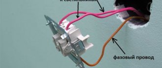
A primitive connection diagram that will be understandable even for a beginner. Here the L-phase wire is connected to the switch, and the other conductors to the lamp
We will consider an example with external wiring, where cables are laid on top of ceilings in a special corrugation.
At the installation site of the switch, the corrugation is fixed to the ceiling using clamps, and an insulated conductor peeks out of it
Under the switch there will be an additional electrical device - a socket, so it would be logical to place the cables of these two devices in the same protective tube.
The cable from the outlet will pass through the overhead switch, so as not to complicate the installation
Mounting a surface-mounted switch: step-by-step instructions
Step one: before starting the installation process, you need to turn off the power to the room. This is easy to do by lowering the switch on the switchboard, which is located on the landing or in the corridor. In order to make sure that there is no voltage, you need to place an indicator screwdriver against the contacts.
If the indicator light does not light up, then there is no voltage
Step two: now you need to disassemble the structure - you should take out the button. In this case, a device with a plastic case and moisture protection is used.
Under the main key, which is located on the case, there is another part - a plastic panel - this should also be removed
Step three: Now you need to remove the internal assembly, which is the main mechanism.
The internal unit is not fixed inside with latches or other elements, so it can be quickly dismantled
Step four: Now you should mark on the wall the place where the switch will be installed. In addition, it is necessary to leave markings for fasteners. To do this, you will have to attach the empty base of the device to the surface. Next, you need to level the housing on the wall, and then put marks where the holes for the fasteners will be located. After that, all that remains is to make indentations in the wall using an electric drill.
We make markings and drill the wall, and then fix the body to the wall with dowels
Step five: next, you need to remove the cover from the top of the body in order to pull the corrugated wiring into this hole.
There should be conductors inside the switch that we will work with
Step Six: Now you should move on to the wiring step. To do this, it is necessary to strip the ends of the wires from the insulating layer (using a knife) by 9 centimeters. After which it is necessary to connect the phase conductor (white) to the terminal marked “L”, and the neutral conductor (blue) to the terminal marked “1”. Next, you should carefully tighten the fasteners and place the mechanism in the body part.
A wire from the socket will pass through the bottom hole of the case, which we will bypass the main unit
Step seven: Now you need to assemble the switch, securing the button in place.
After installing the switch, you should check its functionality by connecting power to the distribution board. If the lamp works after pressing the button, it means that the installation was carried out in accordance with the rules
Video - Connecting a switch
How to replace an old switch: step-by-step instructions
Often, when renovating a residential building, it is necessary to install a new switch. Therefore, in order to understand the principle of these actions, we should consider them in more detail.
Step one: first you need to dismantle the old switch by unscrewing two bolts on the body.
This is what an outdated model of built-in switch looks like and needs to be replaced
Step two: Once the screws are removed, you will need to remove the top cover.
Inside there is an outdated version of the connections, where the ends of the conductors are held on bolts, on each side the base is supported by lugs
Step three: next we have to detect the phase conductor. To do this, you will need to take an indicator screwdriver and bring it to the contacts one by one. At this stage, care should be taken not to touch the conductors with your hands. To protect your hands, it is recommended to wear rubber gloves.
Use an indicator screwdriver to find the phase wire
Step four: after you can determine the phase and neutral wires, you will need to turn off the power at the distribution board. Next, you need to re-check the connections with an indicator screwdriver to make sure there is no voltage. Only after checking it is necessary to begin dismantling the internal device. Using a screwdriver, unscrew the holders that are located at the edges. It is necessary to carefully remove the holders and then wrap the conductors with electrical tape.
It is recommended to use electrical tape of the appropriate colors (white, blue) so as not to confuse the conductors
Step five: now you need to remove the device, straighten the conductors to free up space for installing another switch. Next, you should take a new switch and disassemble it. You will have to dismantle the button and the outer panel to get to the internal assembly, where there are two terminals and holders.
The screws located on each side adjust the degree of clamping, and the top screws are required for connecting conductors
Step six: Next, you need to use a knife or a special tool to remove the insulation from the conductors by about 10 millimeters. After which these wires are inserted into the holes and clamped with screws. It is recommended to tighten them with force so that it is impossible to pull them out. It is important to ensure that insulation does not get inside.
We insert the phase and neutral conductors into the holes in accordance with the markings
Step seven: After connecting the wiring, return the inside of the switch to the mounting cup.
In order to achieve a tight fit of the assembly, it is necessary to tighten the fasteners along the edges
Step eight: now all that remains is to attach the external panel and button.
Electricity should be connected to check the functionality of the switch. Moreover, it is recommended to do this even before the fastenings are fixed.
Connection errors
Many people make a mistake at the stage of searching and connecting the common terminal in the pass-through switch. Without checking the circuit, they naively believe that the common terminal is the one with only one contact. They assemble a circuit in this way, and then for some reason the switches do not work correctly (they depend on each other).
Remember that on different switches the common contact can be anywhere!
And it is best to call it, what is called “live”, with a tester or an indicator screwdriver.
Most often, this problem is encountered when installing or replacing pass-through switches from different companies. If everything worked before, but after replacing one circuit the circuit stopped working, it means the wires were mixed up.
But there may also be an option that the new switch is not pass-through at all. Also remember that the lighting inside the product cannot in any way affect the switching principle itself.
Another common mistake is incorrectly connecting crossovers. When both wires are placed from pass-through No. 1 to the upper contacts, and from No. 2 to the lower ones. Meanwhile, the cross switch has a completely different circuit and switching mechanism. And you need to connect the wires crosswise.
Connection diagram for switch with distribution box
Often, new buildings are handed over to residents in the form of a concrete box with “bare” floors, so you have to independently install doors, carry out electrical wiring, and do surface finishing. Of course, if you wish, you can use the help of a specialist, but this will cost more. To understand how to do the installation yourself, we will look at the connection diagram for a switch, lamp, machine and distribution box.
Junction boxes perform a very important function. They ensure the distribution of electrical wires between points of consumption, i.e. switches, lighting fixtures and sockets. Have you decided to install the devices listed above yourself? Then you need to thoroughly understand the features and order of connecting cables, as well as the basic methods of connecting them. From a special article you will learn about the main methods of connecting cables and the features of disconnecting the box.
The first step is to choose a suitable connection diagram.
The figure above shows a simple option - a diagram in which there is only one light bulb, a switch with one button and an output to the electrical panel. In our case, we will also need to connect a circuit breaker.
The main goal is to install all these elements in their places so as not to confuse the conductors. You will need to mount a junction box in the middle.
Based on preliminary installation, the following diagram will be obtained:
First, a circuit breaker is installed that protects the electrical network from overvoltage and short circuits. To do this, you need to connect the conductors: white - phase, blue - zero, yellow - ground. After which the conductors will have to be routed to the mounting box. Now you should connect them in accordance with the diagram.
If after connection the light comes on, then the conductors are connected correctly - now you can hide the wires in the junction box and cover it with a lid
Pass-through type switch design
Externally, a main switch is no different from a regular switch, except for the presence on the key of a conventional image in the form of two triangles and a diagram of the device on the back side of the dielectric base.
Inside the pass-through switch there are three contacts: two fixed and one movable (changeover), driven by the external key of the device. The changeover contact has two possible operating positions - on one of the fixed terminals. By pressing a key, the movable contact moves from one terminal to another, breaking one circuit and closing the second.
This design feature of the pass-through switch is the basis for a network design in which one lighting fixture can be controlled from two different locations. The neutral and grounding wires from the distribution box are connected to the lighting device, and a break is made in the phase conductor with two pass-through switches, between which two alternative lines are laid.
3 point circuit
To be able to turn the light on/off from three places, you need to buy a cross (cross) switch for two switches. It differs from those described earlier by the presence of two inputs and two outputs. It switches a couple of contacts at once. See the figure for how everything should be organized. If you understand the above, this one is easy to understand.
Electrical circuit for controlling a lamp from three points
- Zero (and ground, if any) is connected directly to the lamp.
- The phase is connected to the input of one of the pass-through switches (with three inputs).
- The input of the second is fed to the free wire of the lamp.
- The two outputs of one three-pin device are connected to the input of a crossover switch (with four inputs).
- The two outputs of the second three-pin device are connected to the second pair of switch contacts with four inputs.
The same diagram, but from a different perspective - where to connect the wires on the housings.
Where to connect the wires
Wiring when controlling the lamp from three places
If you need a circuit with four, five or more points, then it differs only in the number of cross switches (for four inputs/outputs). There are always two switches (with three inputs/outputs) in any circuit - at the very beginning and at the very end of the circuit. All other elements are cross devices.
Connection diagram for pass-through switches for 5 points
Remove one “crossbar” and you get a four-point control scheme. Add more and there will be a scheme for 6 control places.
To finally get it all in your head, watch this video.
Parameters of a single-key switch
The main properties include:
- Voltage range from 220V to 250V;
- General then cat 5A to 16A;
- Protected from dirt, moisture and other adverse factors;
- Resistant to mechanical stress;
- It does not stop functioning when temperatures change.
When purchasing, carefully examining the packaging, you will notice the marking 10A 250V. These data tell us that this switch can be used at values no higher than 10 amperes and a power of 250 watts.
Operating procedure
In this instruction we will try to combine the general procedure for installing a single-key switch, both for external and hidden wiring.
You only have to deal with two wires. One of them is “phase”, the second is “zero”. When connected to a phase, the light bulb in the indicator screwdriver lights up, but when in contact with zero, it does not.
- Turn off the electricity at the distribution board or otherwise de-energize the power grid.
- If necessary, strip the wires with a knife. If they are attached to the switch with bolts, you need to remove 1 centimeter of the wire from the insulation. If self-clamping connections - then only 0.5 cm.
- Remove the key. You can use your hands or a thin screwdriver (an indicator screwdriver will do).
- Remove the protective frame, which is mounted to the body either with screws or latches.
- Install the backing and attach the switch to it (for external wiring).
- Connect the stripped ends of the wires to the switch contacts. When screwing the screws, be sure not to overtighten so as not to damage the wire.
- Place the housing in the socket box and use a screwdriver to lift the fixing tabs. Here you need to achieve maximum contact, but not tear off the screw heads.
- Put the frame in place, then attach the key with your hands.
- Turn on the circuit breakers on the switchboard and check operation.
Placement – convenience and safety
Before installing the switch, you should consider the most convenient location for installation and subsequent use. The most advantageous area is located near the entrance doors (from the side of the door handle), but there may be exceptions (for example, next to the head of the bed).
Before drawing up a wiring project, it is better to look at the official document - PUE (electrical installation rules), which regulates some of the nuances of installation. For example, clause 7.1.48 states that the switch must be located at least 60 cm from the shower stall, and clause 7.1.50 allows it to be installed no closer than 50 cm from the gas pipeline.
The installation of control devices in bathrooms and saunas is prohibited; they must be taken outside the room (usually into the corridor).
Why do you need a crossover switch along with 2 pass-through switches?
Two groups of lamps. When considering it, the following nuances can be noted: All work is performed only with the circuit de-energized. Therefore, let's look at how to properly connect a switch along with a lighting fixture, a circuit breaker and a junction box. Switches from the French company Legrand are distinguished by their wide range and reliability. When choosing a location, you need to take into account the location of all the elements of the circuit and choose the shortest path to connect them. The main convenience of this design is that, if necessary, you can make them yourself.
There are many places in an apartment or house where the ability to turn off the lights from several points is useful. Using a screwdriver, unscrew the screws and remove the plastic cover. Assembly of Legrand Valena Information! Wiring diagram for walk-through switches ABB Zenit: How to connect wiring diagram walk-through switches ABB Basic Wiring diagram for walk-through switches Anam To the main page xnacmllexpcq1j.
If the rooms are not too far from each other, then it is better to make all connections in one junction box. This is very convenient if you are planning a designer renovation or simply do not want to re-decorate the room.
But there are often cases when this method of controlling lamps is inconvenient. How to connect a two-key pass-through switch
Related article: Electrical wiring repair
Switches for small lighting fixtures
Single-key switches for various lamps are installed directly on the cord from the lamp. This method increases the safety of use. And it greatly simplifies use; there is no need to disconnect the device from the network.
The switch is very compact and consists of a contact group; when the position of the key changes, it supplies or disconnects the current supply. Such switches are suitable for a power of 4A. For small lighting fixtures, this switch performs its function perfectly.
One switch for two lamps
As already mentioned, the devices control two groups of lamps, which means you can install the bathroom and corridor on a two-key switch. To do this, we bring the wires from both lamps to the wires and the location of the switch, combine each of them into separate groups, connect them with terminals and attach them to the switch. For large rooms, we recommend reading the article on how to connect a pass-through two-key switch.
Installing a light switch for two rooms is done in the same way.
Installation tips:
- combine groups thoughtfully (for example, kitchen-toilet, corridor-bath, living room-room, etc.) then there will be no cable overuse;
- install switches within easy reach: not behind a chair or cabinet;
- a more powerful switch must be connected to the lamp and fan, taking into account that in addition to the main cables, there is a wire responsible for powering the fan itself;
- We recommend using switches with simon indication;
- in order to connect the device correctly, you must look at the wiring layout, especially when connecting to two power sources;
- If you have not had such experience before, we recommend that you first watch a video of how to install the switch.
Installation of surface-mounted switch
If you are installing a surface-mounted single-key switch, then the process must be carried out in a similar way. But you don't have to drill or dig into the wall to install the box. The disadvantage of such switches is their size.
The process is like this:
- How to install electrical wiring in a wooden house
Urgent entry into a construction SRO
Gasoline power plants
- Determine the location for the holes in the wall.
- Make holes into which you then need to install dowels.
- Connect the wires.
- Attach the switch to the wall.
Such instructions are suitable in cases where you are replacing an old switch with a new one. If there is a need to move the switch, or create a new one, then you need to contact the experts.