To optimize the control of lighting fixtures throughout the house, a system device is used. It helps you turn off the lights with just one button.
The system apparatus consists of individual elements:
1) Contactor is an electromagnetic switch that is designed to remotely close and open electrical circuits.
2) Control module, which consists of:
- a regular 2-key switch.
- electric key scanner (contactless) and cards;
- Wi-Fi or GSM remote control unit.
3). An RCD is an automatic device equipped with a protective shutdown mechanism and ensures the safety of the entire system.
Residual current device Source shikalad.ru
We connect the lighting in the house with a master switch: diagram
To implement such projects, you will need modular contactors for the master switch, for example, ABB ESB 20-20.
The letters and numbers in the name have a specific meaning. The marking symbols mean:
- АBB – name of the organization, manufacturer of the device.
- ESB – circuit breaker series, has a household purpose.
- 20 – current value calculated for the contact element, in A.
- 20-20 – independently closed block contacts with a rated current of 20 A.
Before the pulse arrives, the contact elements are constantly in the open state.
Specifications
The main parameters and technical characteristics are applied to the body of the device, including the ABB contactor. First of all, this is the value of the rated current, the type and number of contacts. Each model and modification has its own indicators.
Most often, switching devices that work with various electrical equipment have the following characteristics:
- The nominal operating voltage of alternating current is 230, 400 and 600 volts.
- The value of the rated operating current, with category of use AC-3, is 12 A.
- Indicators of conditional thermal current with category of use AC-1 – 25 A.
- Rated switching power for voltage 230 V in category AC-3 is 3 kW.
- Rated switching power for voltage 400 V in category AC-3 is 5.5 kW.
- Rated switching power for voltage 660 V in category AC-3 is 7.5 kW.
Video description
Master switch. Contactor. Connection diagram.
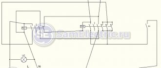
Contactor connection diagram
It is assembled in the following sequence:
- The single-key light switch receives voltage.
- The current passing through the switch comes to connector A2 on ABB ESB 20-20.
- Its other contact (A1) is permanently connected to “zero”.
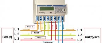
The phase conductor is connected to the 1st connector of the contactor, and the wire connecting the lighting devices is connected to the 2nd.
Single-line diagram of a distribution board master switch Source zen.yandex.com
The system operates on the following principle - when you press the light switch button, voltage comes to contact A1, in fact to the contactor coil. Then, according to the law of electromagnetic induction, it becomes closed. In the absence of voltage, contact A1 is open.
After it closes, electric current flows to the equipment. If you press the button of the single-key light switch again, the line is de-energized. Inside the circuit breaker, the connection is broken and the consumer is disconnected from the voltage.
Another group of lighting devices with a rated current of up to 20A is connected to connectors 3 and 4. In total, the control device can withstand a load of no more than 9-10 kW with an allowable current of 40A.
If you assemble a circuit without a contactor, passing the phase of the power cable that connects all groups of lamps through a single-key switch, serious problems will arise:
- A maximum current limitation is created.
This is the value that the switching element that turns off the light can withstand. The value for a single-key switch is rarely more than 10A.
- The switch will quickly fail.
This is due to the fact that it does not have a contact protection system. Therefore, the terminal pads burn out or the housing melts. Sometimes fires happen for this reason.
Design and principle of operation
You can connect magnetic starters and contactors yourself; you just need to understand the principle of operation of the devices and how to configure the circuits. The magnetic starter consists of a magnetic core and an inductor coil. The magnetic wire has two parts, movable and non-movable , the first is fixed on a spring and carries out free movement, and the second is installed on the body of the device and is motionless.
A coil is installed in the hole of the second part; its location affects the rated contactors of the starter with a coil; they are divided into 12 V and 24 V, 110 V and 220 V and 380 V. And the second part is used for moving and fixed contacts. If power is not supplied, the first part is pressed out by springs, and the state of the contacts does not change and remains in its original form.
As soon as voltage appears, when the start button is pressed or another supply of electricity, the coil regulates the generation of an electromagnetic field, in which the first part of the device is attracted and the arrangement of the contacts changes.
If the voltage disappears, the electromagnetic field zone dries up, the spring part is pressed upward in the moving side of the contactor, and the state of the contacts returns to their original form. This is how an electromagnetic starter works: voltage appears in the contacts, a short circuit occurs, disappears, and an opening occurs. Constant or variable voltage devices are connected to the contact device.
But you need to monitor the device parameters so that they do not exceed those stated in the instructions for use.
Starters are divided into two types with normal closed contacts and normal open contacts. From this you can understand how they work, the first turn off the voltage, and the second turn on; in order for power to be supplied, you need to use number two, and in order to suppress the first.
Master switch: turn off the light with one button
Some residents associate turning off the lighting throughout the apartment using one button with the Smart Home system, since it is not clear how it works. If we control all the devices, when all the lamps are connected to one controller, then the simplest action is to turn off all the lights at the same time before leaving the house.
This function is implemented very simply; you do not need a “Smart Home” for this. For this purpose, a contactor is installed in the electrical panel, equipped with the ability to turn off the lights in all rooms at once based on an external signal. Some people put an additional device on switched sockets.
The contactor, which simultaneously performs the function of a starter, is a modular element mounted on a DIN rail. The mechanism, based on a control signal, turns off and turns on a powerful load, for example, an ABB ESB 24-40 contactor.
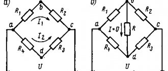
Graphics and symbolism in single-line diagrams
The main function of single-line schematic images is a graphic displaying a particular power supply system of a given facility. It displays the connection of the general power supply and subsequent wiring to individual points. This drawing is made in the form of one general line, which is why it is called single-line. That is, the power supply to each of the consumers is plotted on the plan in the form of a single line.
The symbol for the number of phases in the graphical version is displayed using specially marked marks. If there is one notch, the power supply is single-phase, and if there are three, it is three-phase.
In addition to single linear networks, equipment for switching and protection is applied to the circuit. The first group is represented by contactors, magnetic starters, disconnectors, and the second includes various types of automatic machines, high-voltage circuit breakers, RCDs, safety devices, automatic circuit breakers and load switches.
Small squares are used to display high voltage power switches on a single line diagram. Other protective and switching equipment is applied to the diagram in the form of icons displaying contacts with specific explanatory inscriptions corresponding to the specific device being used.
Hotel circuit and master switch
When there are a lot of lamps and other electrical appliances in the house, and all of them are needed, you can do without turning them on and off at the same time. This is done due to the cross-section of the wires and the current strength of the circuit breaker.
To do this, it is necessary to arrange the electrical wiring in such a way that the circuit diagram includes several circuits that have their own separate circuit breakers. It won't be difficult to do this. With this option, specific groups of electrical appliances are connected to each circuit. Due to this, when all devices are turned on simultaneously, regardless of their power, the current strength in circuit breakers and electrical wiring will not go beyond critical values. This type of electrical circuit is called “hotel” in professional circles.
“Hotel” diagram for connecting a master switch Source rusmarta.ru
To sell you will need to additionally buy:
- a little cable (30-40);
- the required number of machines (depending on the number of circuits);
- master switch, which controls automatic switches through relays.
In appearance, it is a simple key located at the entrance door to the apartment. Such a device allows you to easily turn off the lights in an entire room or turn off a specific group of electrical appliances with a single click.
Elements of electrical circuit diagrams
Schematic diagrams of devices contain a different element base. Communication lines, terminals, connectors, light bulbs are also depicted, but in addition, there is a large number of radio elements: resistors, capacitors, fuses, diodes, thyristors, LEDs. Most of the symbols in the electrical circuits of this element base are shown in the figures below.
Designation of electrical elements on device diagrams
Image of radioelements on diagrams
Rarer ones will have to be looked for separately. But most circuits contain these elements.
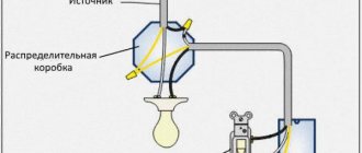
How to equip the system device
The connection diagram for the master switch depends on where it is planned to be used. Different rooms have their own characteristics, so a competent approach is needed.
In the circuit diagram, the circuit breaker is located at the beginning of the electrical circuit. In fact, it is located in the house next to the meter.
Connection diagram for modular contactor Source strojdvor.ru
The operating principle of the circuit is based on the fact that the consumer sets the maximum permitted power consumption, which is required in total for all devices connected to the network. If the parameter exceeds the permissible limit, after a short period of time the circuit breaker will trip and completely de-energize the room.
Due to imprudence, such a decision does not suit the homeowner. Turning off the lights at the most inopportune times creates certain problems with cooking on an electric stove. However, such measures are associated with the need to ensure fire safety. In the event of a short circuit or current leakage, the light turns off instantly.
Master light switch: technical implementation
There are 3 key decisions regarding technical implementation.
- The contactor and master button are installed in the electrical circuit that powers the lighting group.
Before installation, it is better to have a schematic diagram before your eyes. When you press the switch button, the contactor supplies power from the group circuit where the apartment's lamps are connected. This is the most popular option.
- Centralized switching on and off of lights.
Lighting is controlled using a master switch if the entire lighting network in the house is mounted on pulse relays. This option is more expensive and complex; additional special modules are used.
Centralized turning on and off of light in the presence of a pulse relay Source uk-parkovaya.ru
- The most functional and universal solution.
With this option for connecting the master switch, a PLC (programmable logic controller) is used. Thanks to programming, it is possible to change the lighting scheme. Depending on the selected equipment, it is possible to reduce the cost of this option compared to the cost of pulse relays.
Basic images and functional features
Switching devices (switches, contactors, etc.) are built on contacts of various mechanics. There are make, break and switch contacts. The normally open contact is open; when it is switched to operating state, the circuit is closed. The break contact is normally closed, but under certain conditions it operates, breaking the circuit.
The switching contact can be two or three position. In the first case, first one circuit works, then another. The second one has a neutral position.
In addition, contacts can perform different functions: contactor, disconnector, switch, etc. All of them also have a symbol and are applied to the corresponding contacts. There are functions that are performed only by moving contacts. They are shown in the photo below.
Functions of moving contacts
Basic functions can only be performed by fixed contacts.
Functions of fixed contacts
Placement of master switches and non-switched lines
System devices are usually located near the entrance to apartments, in the bedroom or office. These are places where it is more convenient to turn off all lighting devices, as well as centrally control the curtains.
To install non-switchable lines in the electrical panel, a switch or load switch is used to control switchable circuits. This solution is found everywhere.
Advantages of circuit breakers relative to master switches:
- simplicity;
- reliability;
- durability;
- compactness;
- low price.
Disadvantages of switches:
- not convenient to use, unlike master switches;
- non-switchable circuits require additional lighting installation;
- To ensure that devices are turned off and current is regulated, operations are performed manually.
The switch is built into the electrical panel Source grand-electro.ru
Additional lighting is done along the entire line to the electrical panel so that there are no problems in the dark when the lights are turned off throughout the house);
Master Button is a universal solution; it has everything you need. Without going to the switches located throughout the apartment, the device immediately turns off the lights everywhere.
Whether to install master switches or circuit breakers depends on the needs of the residents. The choice is influenced by the advantages and disadvantages of the devices.
Contactors series KM-103
Home \ Contactors KM-103 series
Contactors of the KM-103 series are designed for starting and stopping asynchronous motors with a squirrel-cage rotor.
In combination with an electrothermal overload relay they can be used as a starter motor.
Contactors KM-103 with standard size 9A-95A are equipped with two built-in contacts 1NO+1NC, which expands the possibilities of using contactors. And also more cost-effective, since there is no need to install contact attachments, two additional contacts are enough.
Contactors KM-103 with standard size 115A-630A are equipped with a front contact attachment with additional contacts 1NO+1NC.
A wide selection of contactors with control coil voltages from 24V to 380V expands the functionality of their application.
The principle of operation of the contactor is that when the rated voltage is applied to the coil, it retracts the core, and a group of power and auxiliary contacts is closed. When the voltage reaches the release threshold level, the contacts open.
Accessories for contactors of the KM-103 series: ♦ Electrothermal relay of the RT-03 series; ♦ Contact attachments for side and front installation, series PK-03; ♦ Face-mounted time delay attachments, series PV-03; ♦ Locking mechanisms BM-03 series.
Locking mechanism BM-03:
Main characteristics: ◊ 1 Size for contactors 9-32A ◊2 Size for contactors 40-95
Advantages: Mechanical interlocking combines not only mechanical interlocking, but also electrical interlocking (2NC contacts)
Contact attachments series PK-03-01
Main characteristics: ◊Installation type – side (exclusive) ◊Installed on all KM-103 contactors ◊Number and type of contacts – 1NO+1NC – 2NO – 2NC
Advantages: The PK-03-01 attachment allows you to significantly save on the depth of the cabinet, which will cost less.
Contact attachments series PK-03-02
Main characteristics: ◊Type of installation - front; ◊Number and type of contacts – 1NO+1NC, 2NO, 2NC, 4NO, 4NC, 2NO+2NC, 3NO+1NC, 1NO+3NC
Advantages: Wide range of numbers and types of contacts
Time delay attachments series PV-03
Main characteristics: ◊ Shutter speed types – when turned on, when turned off ◊ Shutter speed ranges – 0.1-30 s, 10-180 s, 0.1-3 s
Advantages: Protective cover preventing unauthorized persons from accessing the exposure time settings
Thermal relay RT-03
Scope of application: Thermal overload relays RT-03 are designed to protect AC circuits and electric motors from overload, phase asymmetry, delayed start-up and rotor jamming.
Advantages: ◊ Duplicate contact of the contactor control coil significantly simplifies the installation of a thermal relay on the contactor ◊ The base allows you to mount the relay separately from the contactor ◊ Possibility of sealing the front panel ◊ Dual function of the test lever - easy check of functionality and indication of the state of the relay contacts (middle position of the lever indicates overload)
Technical characteristics: ◊ Contactor sizes – from 9-18A, 25-32A, 40-95A ◊ Setting currents – from 0.1 to 95A ◊ Trip class – 10A
Base for separate installation RT-03
Main characteristics: ◊ 3 standard sizes:
for contactors 09-18A
for contactors 25-32A
for contactors 40-95A
Advantages: The base allows you to install the relay separately from the contactor
How to connect a pass-through switch
Pass-through switches are used at the beginning and end of the electrical circuit, and a crossover switch is used in the middle of the line. There are other solutions, but less often.
The advantage of control circuits based on pass-through switches: simplicity and reliability. Flaws:
- it is impossible to automate the lighting control system;
- you cannot change the scheme after some time;
- cable consumption is high.
Sometimes a control scheme is implemented for 2 groups of lighting fixtures from N-places on 2-key pass-through elements. However, such a scheme is cumbersome and inconvenient in everyday life. Such switches do not have a fixed “On” or “Off” position.
Connection diagram for pass-through switch Source yandex.ru
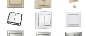
How to connect a switch with one key
The cartridge has 2 terminals; one of the cable cores is inserted into each connector and secured with a clamping screw, then the switch is connected. To do this, the device is disassembled with a screwdriver or by hand: the key attached to the plastic latches is disconnected. If it does not snap off, you need to push it from the back side. After unscrewing 2 screws, the decorative cover is removed.
The connection diagram boils down to the fact that you need to install a single-key switch in the “phase” break.
Connection diagram for a three-key switch Source svetosmotr.ru
How to connect a three-key switch
Connecting a 3-key switch is done in exactly the same way as one and 2-key switches. The difference is in the number of contacts of the outgoing groups: 1, 2 or 3. One supply cable is connected to the input terminal of the switch, and the wire of the lamps is connected to the “output” contacts. The neutral conductors of all lighting devices are combined into one circuit and connected to the “zero” in the box.
Connection diagram for 3-key switch Source vodakanazer.ru
Lighting control circuits through contactors and magnetic starters
To switch on contactors and magnetic starters, push-button posts are used. This is a device equipped with 2 buttons: “Start” and “Stop” or 3: “Forward”, “Stop”, “Back”. These elements are without fixation, with closed and open contacts.
The lighting control circuit is simple and is shown below.
Magnetic starter connection diagram Source uk-parkovaya.ru
Connection diagram for a 220 volt contactor device
When a 220 V starter is connected to a single-phase network, electricity to the magnetic coil (KM 1) will pass through a series of terminals and a thermal relay. They are connected into a single push-button circuit with a push-button start device (SB2) and a stop button (SB1).
When starting a switching device, energy first hits the coil. At the same time, the anchor element is retracted by the core of the starting device. As a result, the power moving contacts are closed and the voltage flows directly to the equipment.