How to control a lamp from several places, and even using regular buttons instead of key switches? In order for this to work, you need to have a pulse (bistable) relay. Some sources call it pulsed, some bistable, so both names are appropriate - choose whichever you like.
Using a circuit consisting of a bistable relay plus any number of buttons (like a bell), you can control the lighting from any number of places. This is needed in long corridors, rooms where it is possible to enter the room from two sides, in bedrooms where the main light can be turned on both at the door and at the bed.
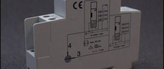
Block diagram of a bistable relay
The operating principle of a pulse relay is shown in the animated figure (look at it carefully):
- The phase potential (L) goes to both the button and the relay.
- When we use the button (S1) to apply potential to the relay, it closes the internal contact of the relay and supplies power to the lamp, even if the button (S1) is released.
- Subsequent application of potential to the relay using the button will turn off the lamp until the button is pressed again.
- Both the lamp and relay must be connected to the neutral (N) wire for everything to function as it should.
Device
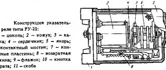
There is a wide variety of pulse relays on the market; due to technical and design differences, you can find different devices. But as an example, we will consider the simplest and most practical principle of operation for understanding (see Figure 1).
Rice. 1. Example of a pulse relay device
The simplest example of a pulse relay consists of the following elements:
- Coil - made of a copper conductor wound on a non-magnetic base, for example, a frame made of textolite, electrical cardboard, etc. Designed to create an electromagnetic field that affects magnetic elements.
- The core is made of ferromagnetic materials that interact with the magnetic field of the coil. Designed to move and perform magnetic influence.
- Relay contact system - consists of movable and fixed contacts designed to transmit a signal.
- Resistive, capacitive and signal elements are used to set the operating logic of the device and indicate the state.
- Timer – sets the time interval for the relay, but is not present in all models; it helps to significantly expand the functionality of the equipment.
Simple connection diagram
The simplest circuit has one button and a bistable relay located with this button. Such a system makes sense only when the relay can be controlled from another source, for example, using a remote control or a central control system (smart home element).
- Mains power 220V is connected to the terminal (L) of the button (S1).
- The electrical potential from terminal (L) is transferred directly to the relay terminal (1) (PB). The potential from this wire will be transferred to the lamp when the relay operates.
- We connect the neutral (N) and protective (PE) wires outside the button (P1). The protective wire (PE) is connected to the PE terminal in the lamp, and the neutral wire is connected to the N terminal of the lamp and to the terminal (A2) of the relay.
- When the button is used to indicate the potential at terminal (A1) of the relay, the relay connects terminals (1) and (2) together with the contact and the lamp turns on. After releasing the button, the contact will remain closed, so the lamp will remain on.
- The change will occur when the button is pressed again and the relay opens the contact, breaking the connection between terminals (1) and (2).
Why only push-button ones?
When using pulse relays, other types of switches are used - push-button, bell or push-type.
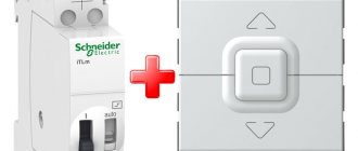
Please note that simple single-key or two-key keyboards will not work here. With rare exceptions, for example for the Meander RIO-2 relay
But more on that later
With rare exceptions, for example for the Meander RIO-2 relay. But more on that later.
Based on this fact, a signal cannot be applied to pulse relays for too long, otherwise its coil will burn out. Some manufacturers warn that the continuous signal time on their models should be no more than 1 minute.
And some children really like to play with such buttons, after which they fail.
Push-button switches resemble ordinary ones in appearance, only inside their design there is a return spring, which after each press returns the key and contact to its original position.
There are also two-key buttons in one housing.
They will come in handy when you want to connect general lighting in the kitchen from one relay and at the same time illumination of the work area of the countertop.
Or in the hall - a chandelier and lighting around the perimeter, plus a separate sconce.
Many people use spring-loaded buttons for doorbells instead of special switches.
Relay control from two places
The electric potential from the phase wire (L) is transferred to terminal (2) of the button (S1), both when the button (S1) and (S2) are pressed. Inside in the diagram you can see the coil symbol which controls the relay contact when we apply voltage to terminals (A1) and (A2).
This way we can attach any number of buttons to control the light independently from different places. If you want to add an additional control from another location, simply add another button into the circuit and connect it in parallel to any other button that controls that lamp, or directly to a relay.
Specifications
In accordance with clause 2.1. GOST 16121-86 parameters of pulse relays must comply with the technical specifications and standards on the basis of which they are manufactured. The most relevant for the operation of bistable switches are:
- the number of push-button switches that can be connected together with a certain type of lamp;
- limits of permissible voltage for switching;
- maximum current load permissible for switching;
- permissible number or power of light bulbs of a certain type;
- overall dimensions must correspond to passport data in accordance with clause 2.2.1 of GOST 16121-86
Fig.7. Example of overall dimensions of a pulse relay
- signal time and response delay;
- mechanical and electrical strength of structural elements;
- wear resistance by number of cycles;
- Climatic performance.
Some of this data can be found on the body of the pulse relay (see example in Figure 8), others only in the device passport.
Rice. 8. Relay characteristics
Bistable relay with two buttons
Now let's take a bistable relay, which can be installed outside the box, for example, in a home switching device. So here is another connection diagram for you to study.
This is essentially the same as in the previous figure, only the shape of the relay has changed.
Useful: Do-it-yourself assembly of an electrical panel in an apartment or private house
Conclusions and useful video on the topic
The video material tells about the device, operation, application and history of the creation of this type of device:
The following story describes in detail the operating principle of solid-state or electronic relays:
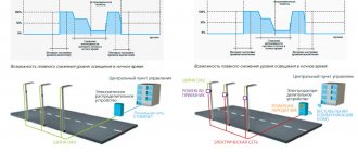
The use of pulse relays is increasingly used in modern electrification systems. Increasing demands for functionality and flexibility in lighting control, material savings and safety create a continuous impetus for the improvement of contactors.
They are reduced in size, simplified in design, increasing reliability. And the use of fundamentally new technologies at the heart of the work allows them to be used in harsh conditions of dusty industries, vibration, magnetic fields and humidity.
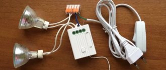
What does a pulse relay look like?
Here is the test system. The bell button will be installed in a box and connected to a bistable relay. On the right side of the relay there are 3 independent electrical connectors connecting the phase, neutral and protective wires. The power cord is currently connected to them.
- Control terminals (A1) and (A2).
- Terminals (2) and (1), to which we connect the power cord and the phase wire to the lamp.
- In the central part of the relay there is a black button that can be pressed manually without bell contact buttons connected by wires.
Tips and tricks
Before purchasing and installing a pulse relay, it would be useful to familiarize yourself with the most common errors that may arise at this stage. Experienced professionals who install switching systems of this type often advise adhering to the following recommendations:
- If you purchase an electronic pulse-type relay, it is better to give preference to models equipped with a timer. With this feature, you can set the power to automatically turn off after a certain period of time. This function will be very useful for organizing lighting on the street, as well as in rooms that are visited frequently, but not for long.
- If you plan to install backlit switches (buttons), you should check with the seller in advance whether the relay can work with such elements of electrical fittings. Many IRs are very sensitive to the appearance of even a small current in the electrical circuit, and the presence of a resistive element will lead to activation of the system. In addition, the device may deteriorate, because the coil will be constantly energized.
- During installation work, all parts through which electric current flows must be well insulated. For this purpose, you can use special heat-shrinkable tubes, as well as PVC insulating tape.
- If there is a small child in the house, then it is better to install the buttons to activate the relay higher. Such products are well insulated and practically safe during operation, but children often start playing with the buttons by holding them on for a long time. Such actions often lead to failure of electromechanical type pulse relays.
- Most models of pulse relays with a coil are designed for 220 V. Such products are very easy to connect to the electrical network, but if you need to ensure a high level of safety in wet rooms, you should choose 12 or 24 Volt models.
- If you need to install several pulse relays that will be used to turn off various lighting devices, then you should choose models with central control. Such a device can be forcibly turned off by applying electric current to one of its contacts. Therefore, if you connect several of these elements to one switch, you can turn off all the lights in the house with one press of a button.
- If there is no desire or opportunity to purchase new buttons to turn on the light using a pulse relay, then you can remake ordinary switches. For this purpose, it is necessary to install small springs under the keys so that after stopping pressing they return to their original position.
- When installing a large number of impulse switches, to save space, the buttons can be placed in one socket box.
A pulse relay is a very interesting product in its design and functionality, which can and should be used to organize more comfortable control of lighting devices. If a high-quality device is selected and the installation of the product is carried out without errors, then such a system will last for many years.
Practical relay connection
Before starting work, be sure to turn off the voltage in the electrical circuit and use a tester to check the presence of 220 V potential on the wires with which we will work.
Connect the power cable (2) to the phase wire connector.
We will run a two-wire cable between the box and the relay. We will connect the brown wire to the connector so that we can press the external button.
The second wire is blue, it will have potential. Let's connect it to the control contact (A2) of the relay.
The next step is to connect the clamp (A1) to the neutral wire connector and also connect the wires to the lamp. The conductors and neutral protection are connected to the appropriate connectors, and the brown wire (phase) to the terminal (1) of the relay so that it operates by receiving the potential supplied to the terminal (2).
The button connection is classic. Connect the power cord to terminal (L) and to terminal (2) of the wire, with the help of which we will transmit short relay control pulses.
Then we attach another button to the circuit. To do this, we will run a two-wire cable between two boxes.
In the second, we can install a backlit bell button so that we can see changes in the potential on it. The connection method is similar. We connect the wires by color in the same way as in the first button.
Everything is ready - click and check the operation of the test system.
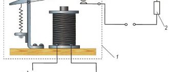
Principle of operation
The principle of operation of a pulse relay is to move the contact group under the influence of the electromagnetic field of the coil that retracts the core. In this case, the device is controlled through push-button channels. One press of the button sends a short-term pulse to the control output, and the contacts go into a stable state - supplying or turning off voltage, which is why it is also called bistable (two stable states). Unlike the same contactor, such a relay is controlled by a single pulse supplied by a button or switch with self-return to its original state, hence the name pulse relay.
For example, consider the operation of a specific device model - RIO-1 (see Figure 2):
Rice. 2. Operating principle of the RIO-1 relay
This device contains two groups of contacts - power and control. Power contacts are represented by terminals 11, 14 and N, control terminals Y, Y1, Y2; it should be noted that in other modifications of pulse relays the markings and number of contacts will be different. Let's consider the purpose of each of the inputs in order:
- 11 – designed to supply power from the electrical network;
- 14 – used to supply phase from a pulse relay to the connected load;
- N – terminal for connecting the neutral wire from the common bus;
- Y – universal input, when a control pulse is applied to which, the relay switches to the opposite state - from on to off and back;
- Y1 – is intended exclusively for switching the pulse device to the on state, that is, if the contacts are already closed, the relay will remain in the same position and has priority over the Y input;
- Y2 – switches the pulse device to the off state, has priority over the other two outputs.
A distinctive feature of RIO-1 is that the power circuit breaks only when the alternating voltage sinusoid passes through zero, which significantly increases the service life of the contact group. But at the same time, the response time differs by 0.3 s, which must be taken into account for the design of precise electronic circuits. The operation of a pulse relay through the supply of signals to each input is clearly displayed on the device’s timing diagram (see Figure 3):
Rice. 3. Timing diagram of RIO-1
As you can see in the figure above, the methods for turning on and off a pulse device are represented by four periods of interaction:
- When you press the button and apply a pulse signal to input Y, the operating voltage will be removed from the power output until the second signal is applied to input Y. This is the simplest option for controlling, for example, a lighting system.
- In the off state, pulse control is applied to input Y1, resulting in an operating rating of 220V at output 14. If you need to turn off the same lighting on site, just send a signal to Y and the power will stop.
- By applying a pulse signal to input Y1, the power circuit is closed - the potential is removed from output 14. When potential Y2 is applied, the bistable relay will turn off and the power circuit will open.
- During this period, switching is performed by applying a signal to input Y. And by applying a pulse signal to Y2, the switch contacts open.
This operating logic allows for the implementation of a number of interesting solutions, both in domestic and industrial processes. This will ensure priority switching of certain objects and electrical equipment located in them.