– one of the most common devices used to automate processes in electrical engineering. In fact, it is an automatic switch that connects or disconnects electrical circuits when the set values are reached or under external influence. Relays are used in industry to automate technological processes, in household appliances that are found in every home, such as refrigerators and washing machines, to protect the network from too high or too low current parameters. Selecting the right device simplifies the classification of relays according to various criteria.
General description of the design
The concept of “relay” unites a whole family of devices of different designs. But in general, a relay consists of three main functional elements:
- Perceiver.
This is the primary element that perceives the controlled quantity and converts it into another physical quantity. - Intermediate.
Compares the received value with the specified parameter. If this value is higher or lower than the specified parameter, then the primary effect is transmitted to the actuator. - Executive.
This element transmits the action to circuits controlled by relays. As a result of such an impact, the following may occur: opening or connecting the controlled circuit, switching current parameters.
The design and operating principle of the primary element depend on what purpose the relay has and what physical quantity (current, voltage, light, heat, etc.) it is set to.
How to test an electromagnetic relay
The performance of an electromagnetic relay depends on the coil. Therefore, first of all, we check the winding. They call her a multimeter. The winding resistance can be either 20-40 Ohms or several kOhms. When measuring, simply select the appropriate range. If there is data on what the resistance value should be, we compare. Otherwise, we are content with the fact that there is no short circuit or break (the resistance tends to infinity).
You can check the electromagnetic relay using a tester/multimeter
The second point is whether the contacts switch or not and how well the contact pads fit. This is a little more difficult to verify. A power source can be connected to the output of one of the contacts. For example, a simple battery. When the relay is triggered, the potential must appear on the other contact or disappear. This depends on the type of contact group being tested. You can also monitor the presence of power using a multimeter, but it will need to be switched to the appropriate mode (voltage control is easier).
If you don't have a multimeter
You don't always have a multimeter at hand, but you almost always have batteries. Let's look at an example. There is some kind of relay in a sealed housing. If you know or have found its type, you can look at the characteristics by name. If the data is not found or there is no relay name, look at the body. Usually all important information is indicated here. The supply voltage and switched currents/voltages are required.
Checking the electromagnetic relay winding
In this case, we have a relay that operates from 12 V DC. It’s good if there is such a power source, then we’ll use it. If not, we assemble several batteries (sequentially, that is, one after another) in order to obtain the required voltage in total.
When batteries are connected in series, their voltage is summed up
Having received a power source of the required rating, we connect it to the coil terminals. How to determine where the coil terminals are? Usually they are signed. In any case, there are symbols “+” and “-” for connecting constant power sources and signs for an alternating type such as “≈”. We supply power to the corresponding contacts. What's happening? If the relay coil is working, a click is heard - this is the anchor being pulled. When the voltage is removed it is heard again.
Checking contacts
But clicks are one thing. This means that the coil is working, but you still need to check the contacts. Perhaps they have oxidized, the circuit closes, but the voltage drops significantly. Maybe they have worn out and the contact is poor, or maybe, on the contrary, they have boiled and do not open. In general, to fully test the electromagnetic relay, it is also necessary to check the functionality of the contact groups.
The easiest way to explain is using a relay with one group as an example. They are usually found in cars. Car enthusiasts call them by the number of pins: 4 pins or 5 pins. In both cases there is only one group. Simply, a four-contact relay contains a normally closed or normally open contact, and a five-contact relay contains a switching group (changeover contacts).
Electromagnetic relay 4 and 5 pins: contact location, connection diagram
As you can see, power is supplied in any case to the pins labeled 85 and 86. And the load is connected to the rest. To test a 4-pin relay, you can assemble a simple combination of a small light bulb and a battery of the required rating. Screw the ends of this bundle to the contact terminals. In a 4-pin relay these are pins 30 and 87. What happens? If the contact is closed (normally open), when the relay is activated, the light should light up. If the group opens (normally closed) it should go out.
In the case of a 5-pin relay, the circuit will be a little more complicated. Here you will need two bundles of a light bulb and a battery. Use lamps of different formats, colors, or somehow separate them. If there is no power to the coil, you should have one light on. When a relay is activated, it goes out and another one lights up.
Main characteristics of the relay
Regardless of the type and principle of operation of the relay, there are several parameters that you pay attention to when choosing this device:
- Response time is the time interval between the arrival of the control signal and the effect on the controlled circuits.
- Switched power is the permissible power of the electrical circuit or electrical installation that the relay will control.
- The setpoint is usually an adjustable parameter that determines the value of the incoming parameter (current, voltage, frequency, pressure, temperature) at which the relay operates.
Device and principle of operation
In the general sense of the word, a relay is an electrical mechanism that closes or breaks an electrical circuit based on certain electrical or other parameters that influence it.
Its non-switching design was invented back in 1831 by J. Henry. And two years later they began to use S. Morse to ensure the functioning of the telegraph.
Two main groups can be distinguished: electromechanical and electronic. In the first type of device, the work is carried out by a mechanism, and in the second, a printed circuit board with a microcontroller is responsible for everything. It is convenient to consider its operation using the example of an electromechanical relay, which is a pulse relay.
When choosing a relay operating mode, you must be guided by the frequency of switching on, the type and magnitude of the current, and the nature of the loads being tested.
Structurally, it can be represented as follows:
- A coil is a copper wire wound around a base of non-magnetic material. It can be insulated with fabric or coated with varnish that does not allow electricity to pass through.
- A core containing iron and activated by the passage of electric current through the turns of a coil.
- A movable armature is a plate that is attached to the armature and exerts an influence on the closing contacts.
- The contact system is a direct circuit state switch.
The operation of a relay is based on the phenomenon of electromagnetic force. It appears in the ferromagnetic core of the coil when current is passed through it.
The coil in this case is a retractor device. The core in it is connected to a movable armature, which activates the power contacts, carrying out switching. They can be of normally open/normally closed type.
Sometimes a contact block may contain both open and closed types of connection.
When the circuit is turned on, the mechanism fixes this position, which changes when the pulse is applied again and is fixed again until the next change
An additional resistor can be connected to the coil, which increases the accuracy of operation, as well as a semiconductor diode, which limits the overvoltage on the winding.
In addition, the design may contain a capacitor installed parallel to the contacts to reduce sparking.
The operation of the device can be more clearly represented by dividing it into several blocks:
- the performer is a contact group that closes/opens the electrical circuit;
- intermediate - the coil, core and moving armature activate the executing unit;
- control - in this relay converts an electrical signal into a magnetic field.
Since a single electrical impulse is required to switch the position of the contacts, we can conclude that these devices consume voltage only at the moment of switching. This significantly saves energy, unlike conventional pass-through switches.
The second type of pulse relay is the electronic type. The microcontroller is responsible for its operation.
The intermediate block here is a coil or semiconductor switch. The use of elements such as programmable logic controllers in the circuit makes it possible to supplement the relay, for example, with a timer.
This type of device has no mechanical moving elements. The work is carried out by a sensor that recognizes the control signal and solid-state electronics that switches the circuit
Types of relays: contact and non-contact
According to the design of the executive component, relays are divided into contact and non-contact.
Contact
They influence the controlled circuit using electrical contacts. Opening or closing them completely disconnects or closes the electrical circuit. The following materials are used to make contacts: copper, silver, tungsten. Number of contacts – up to 10 pieces. Four- and five-pin relays are used in automobile electrical circuits to switch and switch circuits.
Contactless
Such relays act on the controlled circuit by changing the electrical parameters of the output electrical circuits - capacitance, resistance, inductance, current or voltage.
Features of the indicating relay
Indicating relays are used to record the action of relay protection. The current flowing is short-term. The contacts are returned from the actuated state to the working state by the maintenance personnel.
Indicating relays are used as an action indicator in AC or DC electrical circuits.
They can be connected in series (react to the appearance of current) or in parallel (react to the appearance of voltage).
The design of the indicating relay may include the following elements: casing; base; core; winding; anchor; checkbox; bracket and its fastening; return spring and button.
Classification of relays by switching method
Primary
These devices are connected directly to the circuit of the element they are intended to protect. Their advantages are that instrument transformers, operating current sources, and control cables are not required.
Secondary
Connected to a circuit using secondary transformers. This is the most common type of relay. Their advantages are insulation from high voltage, the ability to locate the device in a place convenient for maintenance. Secondary relays are available as standard. They are designed for a current of 5 (1) A and a voltage of 100 V and can be installed in any electrical circuit, regardless of their current and voltage.
How to choose a relay?
The selection of indicating relays in most cases is made according to winding data with a series winding.
Taking the known value of the resistance of the intermediate relay winding, from which the serial winding of the index relay is supposed to be turned on in series, the current passing in the circuit is calculated. The winding resistance of the pointer device is not taken into account. It should also be taken into account that the voltage may drop to approximately 80% of the standard DC operating current circuit.
Tip No. 2: Based on the calculated value of the operating current, it is necessary to select the type and brand of the indicating device, according to which the resistance of the relay winding is calculated.
Types of relays by purpose
According to their purpose, these devices are of three types - control, protection, alarm.
Control relay
These relays are primary. Mounted directly into the electrical circuit. Their role is to turn on and off individual elements of the circuit. They can be used independently or as components of low-voltage complete devices - boxes, panels, cabinets.
Protection relay
Perform the functions of turning on, turning off and protecting devices with thermal contacts - electric motors, fans. When the temperature is exceeded, the thermal contacts open. The equipment can resume operation only after the thermal contacts have cooled to the set temperature.
Alarms
Such relays are installed in security systems of vehicles, enterprises, and local areas. They are used to generate a signal when a set value of a parameter that is under control is reached (current, voltage, frequency, pressure, temperature, acoustic parameters and others).
Types and characteristics of pulse relays
Pulse relays can have a modular design for installation on a DIN rail in a panel, but devices of various sizes and shapes with a different mounting method are also available. Modular devices produced by different manufacturers may also differ in appearance. For example, pulse relays from ABB and Schneider Electric have operation indicators and a manual mechanism control lever.
It will be interesting Description and principle of operation of solenoids
The designation of the connection terminals may also vary. As development progresses, products of the same brand also change. For example, a relay of the previously popular E251 series from ABB, no longer in production, looks like this, and its analogue E290 now has a slightly different look. Series from the same manufacturer also differ in internal circuitry. The main characteristics of pulse relays are:
- Number and initial condition of contacts;
- Rated control voltage;
- Coil actuation current;
- Rated current of the power circuit;
- Control pulse duration;
- Number of connected switches;
The last indicated characteristic depends on the presence of backlight lamps in the switches, the total current of which can lead to the operation of the coil. If the pulse relay is electronic, then it is susceptible to radio interference and interference from surrounding power circuits. Since there is a wide variety of bistable relays, without reference to a specific manufacturer, we can only consider a generalized connection diagram.
Relay operation circuit
A common feature of these relays is that they do not have built-in overload protection and must be protected by circuit breakers.
Since a small current is required to operate the coil, compared to the switched load, the control circuits can be carried out using cables with a core cross-section of 0.5 mm², but in this case, a separate circuit breaker must be installed for this electrical wiring to prevent the wires from catching fire when they are short circuit.
As a rule, manufacturers indicate the time during which the coil can be energized. For example, with ABB it is not limited, but with less famous brands, pulse relays can heat up when there is electric current in the coil circuit for a long time, therefore, when buying a pulse relay, it is necessary to clarify this parameter, because there may be cases when accidentally moved furniture will cause constant pressing the switch button.
If you look at the ABB catalog, you can see that there are pulse relays (old series - E256, new analogue E290-16-11/), which have one normally open and one closed contact, actually operating in switch mode. Such devices can be used to control lighting systems in production, to switch between main and emergency lighting. Thanks to this function, the production room will never be in the dark due to the fault of personnel who forgot to turn on the emergency light - switching is carried out with one press of the switch key.
Pulse relay with digital control
It is also possible to control the lighting both locally (one pulse relay is controlled using several parallel connected buttons) and centrally (simultaneously for several identical devices) using two keys - on and off. For example, E257 series relay wiring diagram. Here, by pressing the central buttons (ON, OFF), all relays are controlled, plus each has its own local control. The updated ABB line uses the principle of combining modules to create multi-level control systems.
The use of different control voltages also expands the functionality of lighting control devices. For example, the impulse relay of the E251-24 series (its updated analogue E290-16-10/24) is controlled by a constant voltage of 12V (or alternating 24V), which makes the operation of switches located in humid environments where there is a risk of electric shock safe.
It will be interesting What is a thermal relay
Such a device can be successfully used to control lighting in a bathhouse or sauna, where the use of devices operating with mains voltage is not allowed. In addition, the low-voltage control signal can be generated by various computerized devices, which allows automation of lighting control processes.
Types of electromechanical relays
The most common type of electrical relay is electromechanical. These include: electromagnetic, induction, electrothermal devices.
Electromagnetic
One type of electrical relay is electromagnetic. The design of this device includes: a winding with a steel core, a group of movable contacts that make and break a controlled electrical circuit. Let's consider the principle of their operation:
- A control current is supplied to the core coil.
- A magnetic field is created in the core under the influence of electric current, attracting the contact group.
- Depending on the type of relay, the contacts close or open the electrical circuit.
A variety of electromagnetic relays are polarized, which differ from neutral ones in their ability to respond to the polarity of the control signal. The opening or closing of the contacts depends on the polarity of the electromagnet connection. They have higher sensitivity compared to neutral relays. Such devices can only be used in DC circuits.
Electrothermal (thermal)
Thermal relays are a complex of bimetallic plates, for the manufacture of which metals with different expansion coefficients when heated are used. Such relays can be used as protective devices: when the temperature set by the regulator is exceeded, the contacts are disconnected and the flow of current to the consumer is stopped.
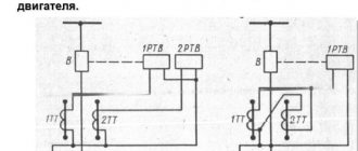
Typically, thermal relays are used in household single- and three-phase networks when connecting electric motors. When the load on the engine increases above a set value, the bimetallic relay heats up, which, when a certain temperature is reached, opens the electrical circuit. The engine stops running. After the bimetallic plates cool, the circuit closes and the engine resumes operation. Thermal devices can be equipped with a wheel that adjusts the engine shutdown temperature and a forced start button.
There is a type of thermal relay in which bimetallic plates are replaced with a low-melting alloy. They operate almost instantly - when a certain temperature is reached, the metal melts and the circuit opens. The principle of operation of such devices is similar to the principle of operation of fuses. After operation, such a relay, installed directly on the equipment as a last resort against burnout, must be replaced.
Induction
The operating principle of these devices is based on the interaction between alternating magnetic fluxes and currents that form alternating magnetic fluxes. Induction devices are designed for use in alternating current circuits only. There are three types of induction relays - with a frame, a disk, and a cylindrical rotor (“glass”). These devices are widely in demand in relay protection and automation systems.
Purpose and principle of operation
In many industries, especially the energy sector, switching of power sources and consumers is carried out constantly - both by automation and protection, and directly by personnel. Each of these switchings requires accounting, control and careful analysis to prevent emergency situations and improve the efficiency of system operation management.
The RU-21 indicator relay in the U4 climatic version has been produced since the times of the USSR
The operator’s senses are not able to detect the fluctuations of the algorithms in the electrical circuit, which must be determined in order to make one or another operational decision. The reliability and uninterrupted power supply often depends on such decisions.
To detect deviations in the network, indicating relays are installed in the circuits, changing the initial state when a certain value changes in the device to be monitored. Such relays are called indicating (signal) relays; there is also a special designation - blinker.
Blinkers are able to indicate the operation taking place inside the controlled device. The contacts of such devices are used in communication and communication circuits with current limitation, the strength of which should not exceed 2A.
Indicating devices allow the operator or dispatcher to monitor the functioning of systems and their protective circuits and automatic devices by:
- indicators;
- audio signals;
- location of signs.
The element used to collect and supply data is an indicating relay. By means of it, the appearance of voltage or current is monitored at a specific interval of the circuit. After arriving at the insertion, the device is triggered, the contacts are moved to a certain position and a command is given to move the pointer.
The part will be located in this position until the operator inspects the relay and records the completed operation. The element then returns to its original position.
The indicator relay performs the following functions:
- switches on when switching to the winding circuit to be monitored by lifting the load or tensioning the return spring of the alarm element;
- triggers when any violations are detected in the system subject to control;
- returns to the normal operating position manually after the operator monitoring the system pays attention to the operation.
Other types of electrical relays
Solid State
These electronic devices are compact and durable due to the absence of rubbing mechanical parts. The mechanical work here is performed by semiconductor elements - bipolar and MOS transistors, thyristors, triacs. Compared to solid-state ones, they have the following advantages:
- Low noise level during operation.
- Very high mean time between failures, which is 100 times or more greater than the service life of electromagnetic devices.
- The response speed is a fraction of a millisecond; for electromagnetic ones it is 50 ms - 1 s.
- Power consumption is 95% lower.
However, solid-state relays have not only advantages, but also disadvantages. One of them is poor resistance to surge voltages, which are practically not dangerous for electromagnetic relays. When using solid-state relays, it is necessary to provide a circuit design that limits these pulses. There are also disadvantages - heating during operation, the presence of leakage currents, leading to the presence of voltage on the phase wire even when the relay is turned off.
Solid-state relays are used in temperature control systems, in which heating elements are used as heaters, in industrial automation, telemetry, equipment mechanisms used in the metallurgical and chemical industries, in medical equipment, and military electronics.
Reed switches
This type of relay is a reed coil. This is a cylinder filled with an inert gas, or inside of which a vacuum has been created. Inside the cylinder there are connecting elements made of permalloy - a precision alloy (an alloy with a precisely specified chemical composition), including iron and nickel. These connecting elements are in the form of wire with contacts. They are coated with silver or gold plating. The reed switch is placed in the middle of an electric magnet or within the range of its field. When current is applied to the winding of an electromagnet, a magnetic flux is formed, which locks the contacts. Reed relays can perform the following functions: making, switching, breaking. The advantages of these devices are compact dimensions, affordable price, and the absence of rubbing parts, which extends their service life. The fact that the contact group is located in an inert gas or vacuum and is reliably protected from moisture increases the reliability of the relay.
When using reed relays the following should be avoided:
- the close presence of an ultrasound source, which will negatively affect performance;
- exposure to foreign magnetic fields;
- mechanical damage.
The flask is usually made of glass, so it must be protected in every possible way from mechanical influences. If the bulb is broken, the contact group will not operate. Reed relays can only be used in systems in which the power supply parameters are within the limits established in the technical documentation. If too high a current is applied, the contacts will open. Malfunctions in the operation of reed relays are also observed in cases where current is supplied at too low a frequency.
Photoelectronic (photo relay)
The basis of a photoelectronic relay is a semiconductor element - a photoresistor, the resistance of which varies depending on changes in illumination. Photo relay is a device widely used by public utilities. It is reliable in operation and provides significant energy savings and safety on the streets. When the illumination increases, all lighting equipment turns off, and when darkness falls, it turns on. Most of these devices are equipped with a threshold regulator and a mechanical switch.
Device
These devices come in all types and sizes. From miniature relays with two contacts, to several dozen in a repeater relay. In all of them the design principle is the same. The intermediate relay device consists of an electromagnetic control coil, a magnetic core, a spring mechanism and a group of contacts. You can learn more about the design of the device by looking at the picture below:
The industry produces a wide range of devices for a variety of control voltages from 5 volts to 220. They can be designed for alternating “AC” voltage and constant “DC”.
Outwardly, they are practically no different. The only difference is in the design of the magnetic circuit. For alternating current it is made up of a group of plates, and for direct current it is solid. This is done to reduce heating losses in the magnetic core during the passage of alternating current.
As for the technical characteristics of devices, they are different for each type. For example, for the RE series they will look like:
For industrial purposes, blocks for intermediate relays are manufactured for installation on a DIN rail. Relays and sockets for them are also available with a wide range of connector types. This is done for ease of operation within the same device, when there are models of different voltages, and one type has not been replaced by another due to inattention.
Types of relays by type of incoming parameter
According to this parameter, relays are divided into: current, power, frequency, voltage, pressure, acoustic values, amount of gas. Devices can be maximum and minimum. Relays that operate when a given value is exceeded are called “maximum”, and when it falls below a given level, they are called “minimum”.
Current relay
Current relays react to sudden changes in current and, if necessary, turn off an individual load or the entire power supply system. The maximum current value at which it is necessary to disconnect consumers is set by the regulator.
Voltage relay
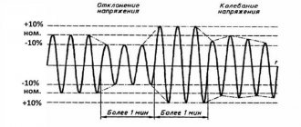
Voltage relays react to voltage levels and are switched on via voltage transformers. Used to control voltage phases in electrical networks and protect electrical appliances. The basis of such a relay is a quick response controller that monitors voltage deviations outside the established limits. The generally accepted standard for operation of such relays is below 170 V and above 250 V.
Frequency relay
They are used to control the frequency of alternating current, which should be equal to 50 or 60 Hz in single- and three-phase networks. Usually have fixed response delays. The opening thresholds of the controlled circuit can be adjusted. The operating mode of this device may include the presence of a “memory” of an accident.
Power relay
The power limiting device operates similarly to a load current limiter. If the set power threshold is exceeded, the consumer is switched off. Power limiting relays are often equipped with an automatic reset function. That is, after the load is reduced, the operation of the equipment resumes automatically.
Pressure switch
A pressure switch is an important device used in pumping equipment to control pressure differences in water, oil, oil, and air. There are two main types of such devices – electromechanical and electronic.
Electromechanical relays have a special element in their design that responds to changes in pressure in the system - a flexible membrane that bends under the pressure of liquid (air) in the system. It is connected to two springs, one of which is adjusted to the minimum permissible pressure, and the second to the difference between the upper and lower limits of pressure in the system. When the pressure in the system drops below the minimum threshold, the relay turns on the pumping equipment, and when the upper threshold is exceeded, it turns off. These are simple and reliable devices, but not very easy to use. The operator has to regularly check the settings and adjust them if necessary.
Electronic devices have a more complex design. Limits can be set very precisely and are not required to be monitored during operation. Electronic devices are sensitive to water hammer, so they are equipped with small hydraulic tanks (volume - approximately 400 ml). An electronic pressure switch is installed between the pumping equipment and the first water collection point.
Acoustic relays
Acoustic relays respond to changes in acoustic quantities - the frequency of the sound wave, its pressure or the acoustic characteristics of materials - absorption and reflection coefficients. The operating principle can be mechanical or electrical. Mechanical acoustic devices have a membrane that bends under the pressure of sound waves, and when a certain pressure value is reached, the contact closes. Electrical acoustic devices include: a receiving organ (microphone, filter), an amplifier, and an output electrical relay.
Devices that respond to any noise are often used in conjunction with a lighting system. They react to any noise in the room and give a signal to turn on the light. They are usually installed in corridors and staircases. Acoustic relays are also widely used in security systems and “smart” toys.
Gas relays
These devices are used to provide gas protection. They are a metal body embedded in the oil line. The relay is normally filled with oil and its contacts are open. As the gas content increases, they fill the upper part of the relay, simultaneously displacing the oil. The float included in the design lowers as the oil level decreases, rotates around its axis and causes the contacts in the signal circuit to close. The generated signal warns of high gas contamination in the environment.
What is a time relay, what is it used for and where is it used?
This device, designed to turn an electrical circuit on and off automatically, after a certain time interval, is used in electrical engineering and more often in everyday life. Based on the principle of operation, they are divided into the following types:
- Electromagnetic
- Pneumatic
- With clock mechanism
- Motor
- Electronic
In electrical engineering, there are also interval relays; they are used to create an interval switching on of a circuit with a certain time delay after a given signal, when it is necessary to switch on at an interval after switching on or off.
Household appliances are mechanical and electronic. Today on the market you can more often find electronic devices with a wide range of functions. The design is a simple circuit with a magnetic coil and a contact group; the main difference from other devices is the built-in integrated circuit that controls the power supply to the coil.
In mechanical devices, the integrated circuit is replaced by a special mechanism resembling a rotating disk. Due to the rotation of the disk and the movement of special marks on it, the circuit is turned on or off at a certain time.
A time relay is an incredibly useful device that has found its application in many areas of life; it is actively used to control the power of electrical appliances from 220V, control ovens, heated floors, washing machines, heating and air conditioning systems.
For example, when you need to turn on the power supply to a water pump in your country house to collect water without your participation and turn it off in time to protect it from running dry. Or completely cut off the power grid at certain hours in order to save electricity.
Intermediate relays
“Intermediate” is a relay that plays not a main, but an auxiliary role in the circuit.
Designed for installation in automatic circuits and control circuits. Its functions are to increase the number of contacts of the main relay, when it is necessary to close or open several circuits, close one and simultaneously open another circuit, and perform other tasks. They are used in circuits for amplifying and converting electrical signals, storing information and programming, distributing electrical energy with controlling the operation of individual elements, and interfacing elements of electronic equipment with different principles of operation. Often, intermediate functions are performed by electromagnetic relays, which, depending on the design and area of application, have the following types of contacts:
- Normally open (closing). In the absence of power supply they are in an open state. When voltage is applied, they close.
- Normally closed (opening). In the normal state, such contacts are in a closed state, and when power is supplied, the contacts open.
- Reversible. In such relays, in the absence of voltage, there is a middle contact closed with one of the fixed contacts. When current is applied, the middle contact breaks the connection with the first fixed contact and closes with the second fixed contact.
Types of indicating relays
- RU-21. They are used in protection circuits to indicate the operation of relay protection and protection devices. For example, the RU-21/0.006 modification is designed for operation under direct current conditions, the response value of which is 0.006 A.
- RU-11. Used to signal an emergency condition in electrical circuits of direct (up to 220 V) or alternating current (up to 380 V at a frequency of 50 Hz and up to 440 V at a frequency of 60 Hz). Can be used in automation devices, including earthquake-resistant ones. Used at altitudes up to 4300 m above sea level. The temperature range is from minus 50 to plus 55 degrees. The RU-11/0.25 modification is operated under alternating voltage conditions, the response level of which is 0.25 A.
PRU-1 .
Used for visual monitoring of the operation of automation and protection circuits. Modification PRU-1/0.01 can be used in direct current conditions, the response value is at the level of 0.01 A. The optimal design of the indicating relay is selected taking into account operating conditions and requirements.
Relay designation on the diagram
Relay designation on a circuit diagram
On electrical diagrams, a relay is designated by a rectangle, from the largest sides of which the power terminals are shown. The functional purpose of the relay is indicated in the diagram by the letters:
- KA – current;
- KV – voltage;
- KB – blocking;
- KBS – blocking against repeated switching on;
- KH – index;
- KL – intermediate;
- KQ – fixing the switch position;
- KSV – voltage circuit control;
- KSP – pressure control;
- KSH – pressure control;
- KSL – liquid level control;
- KSR – speed;
- KSQ – substance composition;
- KW – power;
- KZ – resistance.
Connection diagram
This diagram for connecting a pulse relay shows that control occurs through spring return switches (buttons) connected in parallel to each other. To organize a control circuit, it is enough to connect a thin two-wire wire to the switches, and the lighting power wire is connected to the contacts of the bistable relay. Thus, the circuit is simplified, installation is reduced to laying wires from the buttons to the bistable device, and simply connecting them in parallel.
Please note that there are models that have backlit buttons, otherwise the backlight will have to be turned off; first read the model datasheet. There are also models with coil control from 8, 12, 24 volts to 220 volts
They require a separate power source to operate.
There are also models with coil control from 8, 12, 24 volts to 220 volts. They require a separate power source to operate.
An example of an instruction for a pulse relay RIO-1:
Menu
One of the “stumbling blocks” of high-frequency equipment is the switching elements, because they imply some kind of signal separation and associated losses, especially noticeable as the frequency increases. What does the market offer us to implement the task of switching signals? Solid-state elements based on optocouplers or semiconductors are of some interest, but the inevitable nonlinearity of the pn junction or the drain-source channel of a field-effect phototransistor will introduce signal distortion, especially critical at high and ultra-high frequencies. The best option in this situation would be a pure “metal” contact, which has only an ohmic component of resistance and does not have nonlinear sections characteristic of semiconductors. Now let's look at these solutions in more detail. There is a whole class of electromagnetic relays designed for switching high-frequency signals: these devices are, in some way, a new round of “evolutionary” development of signal relays.
This publication will briefly review relays from Nais, Cll, Axicom and some others. Among the features characteristic of this type of device, it is worth noting the special design of the contact group and the terminals themselves: the reactance of their signal and its attenuation at high frequencies should be minimal. A “careful attitude towards the signal” is realized through the use of open-frame installation, the use of not only coating the contact group itself with rare earth and noble metals (Ag, Au, Ru), but also silver plating of the conductors connecting the terminals and the group of contacts. This technical solution is due to the significant influence of the skin effect (when a high-frequency signal propagates mainly over the surface of the conductor). Shielding of the relay itself and the group of contacts is also used. Such relays may have additional terminals designed to connect the screen to ground. The shielding conductor must be connected along the shortest path to ground, so the developers made an additional pin (or several) for the shield.
This concept was most developed in relays produced by Axicom (Fig. 1). This company has a HF3 series relay, all of whose terminals (including even those to which the coil control voltage is supplied) are made in the form of quasi-coaxial strip terminals. Two versions are available with different impedances - 75 and 50 Ohms (Fig. 2). It is worth taking a closer look at this relay; it is quite unique in itself: produced using surface mount technology with strip-type shielded leads (each lead is surrounded on both sides by additional leads that are connected to ground in such a way that they act as a shield, similar to shielding copper braided coaxial cable - therefore, such a technical solution is often called a quasi-coaxial screen) and containing one switching group of contacts, it can switch a signal with a frequency of up to 3 GHz. The HF3 series uses a polarized coil with an operating power of no more than 0.14 W. There are versions with one and two coils for relays with and without latching. The relay contact group is made of gold, which provides a fairly long mechanical life (107 operations) and good electrical characteristics: maximum switching voltage up to 125 V AC and contact resistance at direct current no more than 100 mOhm. Losses on high frequency alternating current do not exceed 0.3 dB and are shown on the graph (Fig. 3).
Rice. 1. Axicom HF3 relay housings
Rice. 2. Appearance of quasi-coaxial strip leads
Rice. 3. HF3 loss graph
Despite the fairly good characteristics, relays such as HF3 are recommended for commercial equipment: satellite television systems, base stations, video equipment and other equipment operating indoors. But what exists for more stringent conditions? The Cll company, part of the Tyco Electronics concern, produces a very interesting family of MW3/6 relays for military and aerospace equipment (Fig. 4). These relays are produced in sealed, protected housings designed for an operating temperature range of –65...+125 °C, and to reduce high-frequency losses, these housings are quite compact and comparable in size to the housing of military-grade operational amplifier microcircuits. Unlike the Axicom HF3 relay, Cll products are available in solder-through mounting versions and are not equipped with shielding for each pin, but the relay body is completely made of metal, grounded, gold-plated and is itself a very good shield, which allows you to achieve very high frequency switched signal - 6 GHz. Similar relays are installed in the communications equipment units of Apache helicopters. It should be noted that the MW3/6 relay has a fairly high service life (the minimum number of switchings is at least ten million) and good resistance to vibration (the relays can withstand acceleration of 30 g in the frequency range 10–3000 Hz). Thus, the MW3/6 family can be a worthy choice when developing critical equipment components operating in harsh conditions.
Rice. 4. MW3/6 relay family
However, Tyco Electronics' competitors do not stand still: one of the leaders in the production of switching components, the Nais company, otherwise known as a division of the Matsushita Electric concern, produces several series of electromagnetic relays designed for switching high-frequency signals. These relays differ from their Axicom and Cll counterparts in a more conservative design: there are no quasi-coaxial signal leads or gold-plated shielded housings. They are more similar in design to conventional low-frequency signal relays, but due to the original know-how of the manufacturer, the frequency characteristics of the Nais relays are close to those of the Tyco Electronics relays. Among the advantages of Matsushita Electric relays, I would like to note the widest range of design solutions: monostable and bistable, for surface mounting and for soldering into holes. There are several series of relays, differing in housing design, location and dimensions (see table). Further development of Nais high frequency relays led to the development of high frequency switching modules. Physically, these modules are a small shielded case with coaxial leads (Fig. 5), which looks vaguely like a TV tuner - inside this module there are several electromagnetic relays that directly switch signals. Due to the use of a full-fledged coaxial and high-quality shielding, it was possible to significantly increase the frequency of the switched signal to 27 GHz (Fig. 6). Such solutions are new on the market and will undoubtedly be of interest to developers of high-frequency equipment, especially when it comes to inter-unit switching using coaxial connectors, which is not uncommon in communications technology. But Matsushita Electric would never have been at the forefront of the electronic components industry if it had not offered something truly revolutionary. Their latest development is a subminiature relay of the ME-X series (Fig. 7) for switching an RF signal with a maximum frequency of 6 GHz in a leadless design in a BGA package, which has a positive effect on the frequency characteristics of a group of contacts and ensures minimal signal loss. Nais' patented MEMS technology (https://www.nais-e.com/pimites/) is used to develop this relay. The manufacturer does not disclose technological know-how, but this technology represents the result of Matsushita’s developments in the field of microminiature and high-speed devices and components. MEMS is already used in the manufacture of not only relays, but also acceleration and pressure sensors. The relay itself has the smallest dimensions of all competing products (only 2.5O4.0 mm) and contains one group of contacts for opening and one for making contacts with gold plating and losses at high frequencies of no more than 0.5 dB.
Table
Rice. 5. Coaxial switches
Rice. 6. Losses in switches
Rice. 7. Subminiature relay ME-X
Recently, Omron, a well-known manufacturer of automation equipment, joined the production of high-frequency relays. It has launched the G6Z series of relays (Fig. 8), which are designed for a maximum frequency of up to 2.6 GHz and are similar in many respects to the RA series relays from Nais.
Rice. 8. Omron microwave relay
Components similar to Tyco/Cll products are produced by Teledyne, which is better known as a manufacturer of automation products. Teledyne produces compact relays in miniature “Military” housings. Typically, these components are placed in housings similar to crystal oscillator housings (Fig. 9). This company's product line includes several types of relays designed for switching high-frequency signals. For example, the RF100 series relays, which contain two groups of switching contacts, are capable of switching signals with frequencies up to 6 GHz and are very similar in design to Cll's MW6 relays. Keeping up with the times, Teledyne began producing the new GRF180 relay for SMD mounting (Fig. 10), which is also designed for switching signals with a frequency of up to 6 GHz and is designed for use in radio relay stations, satellite television systems and precision measuring instruments. GRF180 has improved vibration protection, allowing it to withstand single impacts with acceleration up to 100 g and vibration loads up to 30 g at frequencies up to 500 Hz. Such relays can be recommended for wearable equipment and equipment operating in harsh operating conditions, such as automotive equipment and wearable communication devices.
Rice. 9. Relay in a “quartz” case
Rice. 10. Teledyne GRF180 relay
Literature
- https://www.nais-e.com/pimites/
- https://www.nais-e.com/relay/mems/
- https://relays.tycoelectronics.com/cii.asp
- https://relays.tycoelectronics.com/axicom/HF3.stm
- https://www.europe.omron.com/en/cor/ecb/home/productselector/Relays/PCB_Signal_Relays/auto_G6Z.asp
- https://www.macom.com/Tech%20Apps/index.htm
Relay REPU-12M
Electromagnetic intermediate-indicating relays of the REPU-12M type with direct and alternating current frequency of 50 and 60 Hz are intended for use in protection, automation, control and signaling devices. REPU relays are produced in climatic versions U3 and T3. The relay of climatic version U3 is suitable for climatic version UHL4. The relay protection degree is IP40 for the housing and IP20 for the terminals.