History of appearance
Work on the invention of the microprocessor has been carried out since the early 1970s. The first company to develop it was Intel. Already in 1971, the first microcontroller 4004 was released, which consisted of 2300 semiconductor transistors and was no larger than the palm of a hand. This became possible after a processor crystal was specially designed for the chip.
Despite its small size, the performance of the microprocessor was not inferior to the Eniac computer, which has dimensions of 85 m3. The peculiarity of this device was that it could only process 4 bits of information.
In the next six months, several more companies announced the creation of similar products.
By the end of 1973, Intel released an 8-charge microprocessor. It was so well designed that it is still considered a classic today.
A few months later, Motorola released its 8-bit microprocessor 6800. It became a strong competitor to the Intel chip, because it had a more significant interrupt system and one power supply voltage. In 8080 there were three of them.
The internal architecture of the 6800 was also different. It did not have general-purpose registers in which both address information and numerical indicators could be stored. Instead, the processor now has another full-fledged battery for data processing and 16-bit registers for storing addresses. Memory work was faster and simpler on the 6800, but the 8080 spent less time exchanging internal information between registers.
Both of these products had both positive aspects and shortcomings. They became the founders of two large families of microprocessors - Intel and Motorola, which still compete with each other.
In 1978, Intel released a 16-bit microprocessor that IBM used to develop personal computers. Motorola did not lag behind its competitor and also released a 16-bit microprocessor, which was used by Atari and Apple.
There are now more than 200 types of microcontrollers. The number of companies producing them has exceeded two dozen. The following are widely used by developers:
- 8-bit Pic microcontrollers from Microchip Technology and AVR from Atmel;
- 16-bit MSP 430 from TI;
- 32-bit ARM from the company of the same name.
Microcontrollers from Renesas Electronics, Freescale, and Samsung are popular in Russia.
PIC
Microchip Technology logo
Opening our parade is Microchip Technology with the PIC series. These MKs differ from each other in their bit depth (8/16/32), set of peripherals and chip housing. Eight-bit options are divided into four families: baseline, mid-range, enhanced mid-range and PIC18. More detailed information is given in the table.
There are also 16-bit “peaks” - PIC24F and DsPIC30/33F. Well, 32-bit ones - PIC32MX. These strange combinations of letters and numbers are part of the chip's identifier. Same as car brands. For example, the widely used stone PIC16F628A is deciphered as follows: family PIC16F6 (Mid-range), and the rest of the name is a pointer to a specific stone. The MKs discussed below may contain even more information in their name.
Microcontroller PIC16F628A
These microcontrollers have an average price. For example, a PIC6F628 stone in Chipdip costs about 150 rubles, and a PIC18F2550 costs 620 rubles.
What is a microcontroller
A microcontroller is essentially a microcircuit that consists of:
- Central processor. It includes a control unit, registers, ROM (read only memory).
- Peripherals, which include I/O ports, interrupt controllers, timers, various pulse generators, analog converters and similar elements.
A microcontroller is often called a microprocessor. But it is not so. The latter performs only certain mathematical and logical operations. And the microcontroller also includes a microprocessor with other elements, being only part of the microcontroller.
What's inside the microcontroller
Microcontrollers / For Beginners /
| What is needed to become a professional program developer for microcontrollers and reach a level of skill that will allow you to easily find and get a job with a high salary (the average salary of a microcontroller programmer in Russia at the beginning of 2022 is 80,000 rubles). Read more… |
Before studying the structure of real microcontrollers, let's look at the structure of an abstract microcontroller to understand what is inside the microcontroller. The microcontroller structure is shown in a simplified manner in the figure (click on the picture to enlarge).
I think that the internal structure of the microcontroller is approximately clear from the drawing. But for beginners, I’ll tell you a little more about each element of this scheme.
CPU (central processing unit) literally translates as “central processing unit”. But in modern language it is usually called a “central processing unit” (CPU), or simply “central processing unit”.
This module receives command codes from program memory, decodes (deciphers) them and executes these commands.
The CPU consists of registers, an arithmetic logic unit (ALU), and control circuits.
In microprocessor systems, the CPU was usually implemented in the form of a separate microcircuit, to which other elements, also made in the form of separate microcircuits, were connected. In a microcontroller, almost all the peripherals are located in one housing.
Program memory is the memory where instruction codes are stored. The sequence of these very commands is the microcontroller program, which you “stitch” into the microcontroller using a programmer.
RAM is a random access memory device. This is RAM, which contains the data necessary for work. Program variables are stored here. Many microcontrollers also have a stack located here.
The clock generator determines the speed of the microcontroller. It generates pulses of a certain frequency. Based on this frequency, the central processor executes commands at a given frequency. Read more here.
The reset circuit is necessary for the microcontroller to start up properly. When resetting, all elements are set to some initial state, from which the microcontroller begins to operate.
The serial port allows you to exchange data with external devices. Not all microcontrollers have it.
Digital I/O lines (ports) are designed to read (input) discrete signals from external devices, such as control buttons. And also for outputting discrete signals, which allows you to control some devices, such as, for example, LEDs.
A discrete signal has only two fixed states: 0 and 1. Typically, 0 corresponds to the absence of voltage at the output, and 1 to the presence of voltage. Although it may be the other way around.
Analog I/O lines (ports) are designed to read (input) analog signals from external devices, such as sensors with analog output (temperature, humidity, etc.). And also for outputting analog signals, which allows you to control devices that require smooth adjustment, such as, for example, heaters. Or for outputting frequency signals, for example, for playing sound.
As already mentioned, a discrete (intermittent) signal usually has only two states (although options are possible - but more on that another time).
The analog signal is continuous.
For example, if we are talking about a voltage in the range from 0 to 5 V, then the discrete signal will have only two values: 0 and 5 V.
An analog signal will have many values throughout the entire range from 0 to 5 V. For example, 1 V, 3 V, 3.75 V, etc.
The timer is used to count time intervals.
A watchdog timer is a special timer designed to prevent program crashes. The principle of operation of this timer is as follows: after starting, it begins counting the specified time interval. The program must restart the watchdog before this period of time expires. If she did not do this, then with a high degree of probability we can assume that the program “hung” (a failure occurred). In this case, the watchdog timer restarts the microcontroller.
Real time timer . Roughly speaking, this is a clock that counts not some abstract periods of time, but rather real (current) time. The current time is used by some devices. For example, such as a time relay or the same electronic clock.
I hope now you can imagine what a microcontroller looks like from the inside. Some of these elements will be described in more detail in the following articles...
| Subscribe to the YouTube channel Join the “Programming Fundamentals” group Subscribe to programming newsletters |
| Microcontrollers for DUMMIES Free newsletter about microcontrollers. The newsletter contains both free information for beginners and links to paid products (books, video courses, etc.) for those who want to delve deeper into the topic. Read more… |
The principle of operation of the microcontroller
Despite the complex design, the operating principle of the microcontroller is very simple. It is based on the analog operating principle. The system understands only two commands (“there is a signal”, “there is no signal”). From these signals, the code of a specific command is written into its memory. When the MK reads a command, it executes it.
Each MK has its own basic sets of commands. And only these he is able to accept and carry out. By combining individual commands with each other, you can write a unique program that will make any electronic device work exactly as required.
Depending on the set of programs contained in the MK, they are divided into:
CISC is a complex of a large number of basic commands;
RISC - only the necessary commands.
Most controllers contain a RISC kit. This is explained by the fact that such a microcontroller is easier to produce, it is cheaper and is more in demand among developers of electronic equipment.
Types of microcontrollers
In fact, unlike auxiliary devices, microcontrollers do not have any standardized classification, which is why their types are often divided according to the following parameters:
- The number of analog and digital pins.
- Total number of pins.
- The number of nuclei that are present in the MK.
- Speed of operations or hertz.
- The volume of RAM and permanent internal memory.
- Sizes.
Depending on changes in certain parameters, you can calculate the connection of the load to the microcontroller and select a device that is ideal for your specific project, both in terms of characteristics and functionality.
Purpose and scope of microcontroller
Due to the fact that AVR microcontrollers are very easy to use, have high integration capacity and low power consumption, their application areas are diverse:
- automotive industry;
- robotics;
- aircraft and shipbuilding;
- industrial equipment;
- electronic children's toys;
- computers, phones;
- electronic musical instruments;
- Appliances;
- medical equipment;
- control of barriers and gates;
- traffic lights, semaphores;
- railway transport.
This is not a complete list of areas of application of MK.
The main purpose of the MK is to control all processes that occur on its platform. From turning lights on or off with a clap to raising the curtains when the light outside changes. In essence, MK monitors the state of certain variables and changes the system under dynamic conditions.
Microcontroller power supply
To operate, a microcontroller, like any electronic device, requires energy. The voltage of the Atmel AVR MK is in the range of 1.8–5.5 Volts and depends on the model and series. Most appliances operate on 5 Volts. But there are also low-frequency models (Attiny 2313), the lower limit of which is from 1.8 V.
In addition, the frequency of the incoming current also affects the operation of the MC. Low voltage also requires low frequency limits. The higher the frequency, the faster certain models work.
So, in order to ensure the operation of AVR series controllers, 5 V must be supplied to all positive inputs, and the zero input must be grounded.
If the model has several power inputs and outputs, then they all need to be connected.
Power is supplied to the analog-to-digital converter through additional filters. This will help eliminate interference that may change the voltage readings. In this case, voltage is supplied to the positive input through a filter choke. And the zero pins are divided into digital and analog. Moreover, they can only connect at one point.
In addition, it is necessary to install capacitors, preferably ceramic ones, at the rate of 1 per 100 nanofarads.
Connection
Through a microcontroller you can connect any device to the local network. As such, we can consider Ethernet. First of all, let's define the concepts.
Ethernet is a set of IEEE 802.3 standards that describe a variety of local network technologies: a common data link layer and a set of physical layer technologies, including optical fiber, twisted pair, and coaxial at various speeds for information transmission.
You can understand how a local network works through the OSI model. It includes several levels:
- Physical. It consists of a twisted pair cable, drivers and transformers through which data is transmitted.
- Duct. Ethernet frames are transmitted through it between local network nodes.
- Network. Packets are transmitted over it. They can be transmitted through several networks that differ in physical and data link layer technologies.
- Transport. Connects nodes together. Before sending data, the transport layer presents it as a network layer packet and transmits it to another node. It can send groups of packets simultaneously. If a connection-oriented protocol is used, then before sending the transport layer establishes a connection, monitors its quality, and only then transmits the data packet.
- Applied. Solves applied problems, those for which it was created. It exchanges data with the outside world using a standard or exclusive protocol.
Each of the subsequent levels is served by the previous or underlying one. This is how vertical inter-level connections are formed. The service features of each level are hidden from the rest.
When two networks interact, each level of one network contacts a similar level of the other. This is how horizontal connections are formed.
Microcontroller control
MK management can be carried out in two ways:
- Wired path. The actuators are controlled through an electrically conductive connection of control circuits and actuators. Switching on - by pressing a button on the control center or push-button remote control.
- Wireless way. This control method does not require a wired connection. A signal is transmitted from the transmitter or remote control (RC) and goes to the receiver.
Wireless connection signals can be:
- Optical. Similar signals control home appliances: TVs or air conditioners.
- Radio. There are several options: Wi-Fi, Bluetooth, etc.
The development of modern means of communication makes it possible to control controllers both through the remote control, being in close proximity to the device, and via the Internet from anywhere in the world via a local network.
Provides support for the Wi-Fi network of the ESP 8266 MK. It can be sold in the form of a microcircuit or soldered like an arduino. It has a 32-bit core and needs to be programmed via the UART serial port. There are more advanced boards with the ability to flash firmware via USB - these are NodeMCU. They can store information recorded, for example, from sensors. Such boards work with various interfaces, including SPI, I2S.
Supports a large number of functions:
- task Manager;
- timer;
- ADC channel;
- generation of a PWM signal at the output;
- audio player and much more.
The board can be used as an independent device and as a module for wireless communication with Arduino.
AVR microcontroller from the inside
A microcontroller from the inside is a computer with its own computing device, permanent and dynamic memory, I/O ports and various peripherals.
Rice. 1. Structure of the AVR microcontroller. Drawing from digikey.com
Inside the microcontroller contains:
- High-speed processor with RISC architecture;
- FLASH memory;
- EEPROM memory;
- RAM memory;
- I/O ports;
- Peripheral and interface modules.
RISC (Reduced Instruction Set Computer) is an architecture with a carefully selected set of instructions that are usually executed in one processor cycle. Modern AVR microcontrollers contain about 130 commands, which are executed very quickly and do not require large expenditures both in terms of intra-processor resources and power consumption.
Microcontroller clocking
The clock frequency of the MK is the number of cycles per second performed by the controller. The higher it is, the more operations it can perform.
There are several ways to clock the MK. They depend on the use:
- Internal RC oscillator. It can only operate at 1, 2, 4, 8 MHz. If you need a different frequency, then it will not work. If it is necessary to use precise time intervals, this method cannot be used either, since its setting frequency fluctuates depending on the temperature.
- External quartz. This method has a more complex connection. The capacitance of the capacitor should be in the range of 15–22 pF. One output is connected to the resonator, and the other is grounded.
- External generator. This generator is also unstable at different temperatures, just like the internal one.
- RC chains. For this circuit, a capacitor with a capacity of 22 pF and a resistor of 10–100 kOhm is suitable.
For the simplest microcontrollers, an internal or external generator and RC circuits are suitable. To design more accurate MCUs, stable clock sources will be required.
AVR MICROCONTROLLER DEVICE
The heart of AVR microcontrollers is an 8-bit microprocessor core or central processing unit (CPU), built on the principles of RISC architecture. The basis of this block is an arithmetic logic unit (ALU). Based on the system clock signal from the program memory in accordance with the contents of the program counter (Program Counter - PC), the next instruction is selected and the ALU is executed. When a command is selected from program memory, the previous selected command is executed, which allows it to achieve a speed of 1 MIPS at 1 MHz. The ALU is connected to general purpose registers RON (General Purpose Registers - GPR). There are only 32 general purpose registers; they are in byte format, that is, each of them consists of eight bits. RONs are located at the beginning of the RAM address space, but are not physically part of it. Therefore, they can be accessed in two ways (as registers and as memory). This solution is a feature of AVR and increases the efficiency and performance of the microcontroller. The difference between registers and RAM is that any operations (arithmetic, logical, bit) can be performed with registers, but data from registers can only be written to RAM.
| Memory |
| Fonneumann and Harvard architecture In 1945, American mathematician John von Neumann formulated the basic principles of modern computers. He proposed an architecture that received his name (von Neumann architecture) and involved storing programs and data in shared memory (1946). Today, this architecture is most typical for microprocessors intended for use in computers. An example is the x86 family of microprocessors. The architecture that involves separate use of program and data memory is called Harvard architecture. Harvard architecture allows the central processor to work simultaneously with both program memory and data memory, which significantly increases performance. |
AVR microcontrollers implement the Harvard architecture, according to which not only the address spaces of program memory and data memory are separated, but also the access buses to them.
Each of the data memory areas (RAM and EEPROM) is also located in its own address space. Program memory (Flash ROM or Flash ROM)
The program memory is designed to store a sequence of commands that control the operation of the microcontroller, and has a 16-bit organization. All AVRs have Flash program memory, which can be of various sizes - from 1 to 256 KB. Its main advantage is that it is built on the principle of electrical reprogrammability, that is, it allows repeated erasing and recording of information. The program is entered into the AVR Flash memory both using a conventional programmer and using the SPI interface, including directly on the assembled board. All AVR microcontrollers except Tiny11 and Tiny28 have the ability to in-circuit programming (ISP function) via the SPI communication interface. All microcontrollers of the Mega family have the ability to self-program, i.e., independently change the contents of their program memory. This feature allows you to create very flexible systems based on them, the operating algorithm of which will be changed by the microcontroller itself depending on any internal conditions or external events. The guaranteed number of flash memory rewrite cycles for second-generation AVR microcontrollers is at least 10 thousand cycles with a typical value of 100 thousand cycles. (The official technical documentation of Atmel Corp. indicates a value of 10 thousand cycles.)
Data memory
Data memory is divided into three parts: register memory, random access memory (RAM - random access memory or RAM) and non-volatile memory (EEPROM or EEPROM).
Register memory (RON and RVV)
The register memory includes 32 general purpose registers (RON or GPR), combined into a file, and service input/output registers (I/O registers). Both are located in the RAM address space, but are not part of it. In the area of input/output registers there are various service registers (microcontroller control registers, status registers, etc.), as well as registers for controlling peripheral devices included in the microcontroller. Essentially, controlling a microcontroller is about managing these registers.
Non-volatile data memory (EEPROM)
For long-term storage of various information that can change during the operation of the microcontroller system, EEPROM memory is used. All AVRs have a unit of non-volatile electrically rewritable EEPROM data memory from 64 Bytes to 4 KB. This type of memory, accessible to the microcontroller program directly during its execution, is convenient for storing intermediate data, various constants, coefficients, serial numbers, keys, etc. EEPROM can be loaded externally either via the SPI interface or using a conventional programmer. The number of erase/write cycles is at least 100 thousand.
Random access memory (RAM or RAM)
Internal Static RAM (SRAM) has a byte format and is used for on-line data storage. The size of RAM can vary among different chips from 64 Bytes to 4 KB. The number of read and write cycles in RAM is not limited, but when the supply voltage is turned off, all information is lost. For some microcontrollers, it is possible to connect external static RAM up to 64K.
| Periphery |
AVR microcontroller peripherals include: ports (from 3 to 48 input and output lines), external interrupt support, timer-counters, watchdog timer, analog comparators, 10-bit 8-channel ADC, UART, JTAG and SPI interfaces, down reset device power supplies, pulse width modulators.
Input/output ports (I/O)
AVR I/O ports have a number of independent input/output lines from 3 to 53. Each port line can be programmed as an input or output. Powerful output drivers provide a current carrying capacity of 20 mA per port line (sink current) with a maximum value of 40 mA, allowing, for example, LEDs and bipolar transistors to be directly connected to the microcontroller. The total current load on all lines of one port should not exceed 80 mA (all values are given for a supply voltage of 5 V). An architectural feature of the construction of input/output ports on the AVR is that for each physical output (pin) there are 3 control/control bits, and not 2, as in common 8-bit microcontrollers (Intel, Microchip, Motorola, etc. ). This avoids the need to have a copy of the port contents in memory for security and improves the speed of the microcontroller when working with external devices, especially in environments with external electrical noise.
Interrupts (INTERRUPTS)
The interrupt system is one of the most important parts of the microcontroller. All AVR microcontrollers have a multi-level interrupt system. An interrupt interrupts the normal flow of a program to perform a priority task determined by an internal or external event. For each such event, a separate program is developed, which is called an interrupt request processing subroutine (for short, an interrupt subroutine), and is located in program memory. When an interrupt-causing event occurs, the microcontroller saves the contents of the program counter, interrupts the CPU's execution of the current program, and proceeds to execute the interrupt routine. After executing the interrupt routine, the previously stored program counter is restored and the processor returns to executing the interrupted program. Each event can be assigned a priority. The concept of priority means that a running interrupt routine can be interrupted by another event only if it has a higher priority than the current one. Otherwise, the central processor will begin processing a new event only after finishing processing the previous one.
Timers/counters (TIMER/COUNTERS)
AVR microcontrollers include from 1 to 4 timers/counters with a width of 8 or 16 bits, which can work both as timers from an internal clock source and as counters of external events. They can be used for precise formation of time intervals, counting pulses at the pins of a microcontroller, generating a sequence of pulses, and clocking a serial communication channel transceiver. In PWM mode, the timer/counter can be a pulse width modulator and is used to generate a signal with programmable frequency and duty cycle. Timers/counters are capable of generating interrupt requests, switching the processor to servicing them based on events and freeing it from the need to periodically poll the state of the timers. Since microcontrollers are mainly used in real-time systems, timers/counters are one of the most important elements.
Watchdog Timer (WDT)
The WatchDog Timer is designed to prevent catastrophic consequences from random program failures. It has its own RC oscillator operating at 1 MHz. As with the main internal RC oscillator, the value of 1 MHz is approximate and depends primarily on the microcontroller supply voltage and temperature. The idea of using a watchdog timer is extremely simple and consists in resetting it regularly under the control of a program or external influence before its timeout expires and the processor is reset. If the program is running normally, the watchdog reset command should be executed regularly to prevent the processor from being reset. If the microprocessor accidentally goes beyond the program (for example, due to strong interference in the power supply circuit) or gets stuck in some part of the program, the watchdog reset command will most likely not be executed for a sufficient time and a complete processor reset will occur, initializing all registers py and bringing the system into working condition.
Analog Comparator (AC)
An analog comparator compares the voltages at two pins of the microcontroller. The result of the comparison will be a Boolean value that can be read from the program. The output of the analog comparator can be connected to an interrupt from the analog comparator. The user can set the interrupt to trigger on a rising or falling edge or on a switch. Present in all modern AVRs except Mega8515
Analog-to-digital converter (A/D CONVERTER)
An analog-to-digital converter (ADC) is used to obtain a numerical value of the voltage applied to its input. This result is stored in the ADC data register. Which of the microcontroller pins will be the ADC input is determined by the number entered in the corresponding register.
Universal Serial Transceiver (UART or USART)
Universal asynchronous or universal synchronous/asynchronous transceiver (Universal Synchronous/Asynchronous Receiver and Transmitter - UART or USART) is a convenient and simple serial interface for organizing an information channel for exchanging the microcontroller with the outside world. Capable of operating in duplex mode (simultaneous transmission and reception of data). It supports the RS-232 standard protocol, which makes it possible to communicate with a personal computer. (To connect the MK and a computer, you will definitely need a circuit for pairing the signal levels. There are special microcircuits for this, for example MAX232.)
Serial peripheral interface SPI
The serial peripheral three-wire interface SPI (Serial Peripheral Interface) is designed to organize data exchange between two devices. It can be used to exchange data between the microcontroller and various devices, such as digital potentiometers, DAC/ADC, FLASH ROM, etc. Using this interface, it is convenient to exchange data between several AVR microcontrollers. In addition, the microcontroller can be programmed via the SPI interface.
Two-wire serial interface TWI
The two-wire serial interface TWI (Two-wire Serial Interface) is a complete analogue of the basic version of the I2C interface (two-wire bidirectional bus) from Philips. This interface allows up to 128 different devices to be connected together using a bidirectional bus consisting of a clock line (SCL) and a data line (SDA).
JTAG interface
The JTAG interface was developed by a group of leading experts in the testing of electronic components (Joint Test Action Group) and was registered as an industry standard IEEE Std 1149.1-1990. The four-wire JTAG interface is used for PCB testing, in-circuit debugging, and microcontroller programming. Many Mega family microcontrollers have an IEEE Std 1149.1 compliant JTAG or debugWIRE interface for on-chip debugging. In addition, all Mega microcontrollers with 16 KB or larger flash memory can be programmed via the JTAG interface.
Clock generator
The clock generator generates pulses to synchronize the operation of all microcontroller nodes. The AVR's internal clock can be driven from multiple reference sources (external oscillator, external crystal, internal or external RC). The minimum permissible frequency is not limited in any way (up to step-by-step mode). The maximum operating frequency is determined by the specific type of microcontroller and is indicated by Atmel in its characteristics, although almost any AVR microcontroller with a stated operating frequency of, for example, 10 MHz at room temperature can easily be “overclocked” to 12 MHz and higher.
Real Time System (RTC)
RTC is implemented in all Mega microcontrollers and in two “classic” crystals - AT90(L)S8535. The RTC timer/counter has a separate prescaler that can be connected in software to either the main clock source or an additional asynchronous reference source (crystal or external clock). Two pins of the microcircuit are reserved for this purpose. The internal oscillator is optimized to work with an external 32.768 kHz crystal clock.
| Nutrition |
AVRs operate at supply voltages from 1.8 to 6.0 Volts. Current consumption in active mode depends on the supply voltage and frequency at which the microcontroller operates, and is less than 1 mA for 500 kHz, 5 ... 6 mA for 5 MHz and 8 ... 9 mA for 12 MHz. AVRs can be switched by software into one of three low-power modes. Idle mode (IDLE).
Only the processor stops working and the contents of the data memory are frozen, while the internal clock generator, timers, interrupt system and watchdog timer continue to function.
Current consumption does not exceed 2.5 mA at a frequency of 12 MHz. Stop mode (POWER DOWN).
The contents of the register file are preserved, but the internal clock generator is stopped, and therefore all functions are stopped until an external interrupt or hardware reset signal is issued.
When the watchdog timer is turned on, the current consumption in this mode is about 80 μA, and when it is turned off, it is less than 1 μA. (All values given are based on a 5V supply voltage). Economy mode (POWER SAVE).
Only the timer generator continues to work, which ensures the safety of the time base. All other functions are disabled.
Under Voltage Reset (BOD)
The BOD circuit (Brown-Out Detection$WinAVR = ($_GET['avr']); if($WinAVR) include($WinAVR);?>) monitors the power supply voltage. If the circuit is turned on, then when the power drops below a certain value, it puts the microcontroller into a reset state. When the supply voltage rises again to the threshold value, the reset delay timer starts. After the delay is formed, the internal reset signal is removed and the microcontroller starts up.
Microcontroller families
All MKs are united into families. The main characteristic by which this division occurs is the structure of the nucleus.
By the core of a microcontroller we mean a set of specific instructions, the cyclic operation of the processor, the organization of both program memory and databases, an interrupt system and a basic set of peripheral devices (PU).
Representatives of the same family differ from each other in the amount of memory of programs and databases, as well as the variety of control units.
All MKs are united into families by the same binary programming code.
Families are divided into:
- MSC-51, manufactured by Intel. Monocrystal MCU based on Harvard architecture. The main representative of this family is the 80C51, created using CMOS technology. And although these controllers were developed back in the 80s of the last century, they are still widely used. And today many companies, such as Siemens, Philips, etc., produce their controllers with a similar architecture.
- PIC (Microchip). MK Harvard architecture. It is based on a reduced instruction set architecture, built-in command and data memory, and low power consumption. This family includes more than 500 different MKs (8, 16, 32-bit) with different sets of peripherals, memory and other characteristics.
- AVR (Atmel). High-speed controllers are developed on our own architecture. The controller is based on a Harvard RISC processor with independent access to program and database memory (Flash ROM). Each of the 32 general purpose registers can act as an accumulator register and a set of 16-bit instructions. High performance of 1 MIPS per MHz clock speed is achieved due to the order of execution of instructions, which involves executing one instruction while preparing for the next one. To support its products, Atmel releases a free and high-quality Atmel development environment
- ARM (ARM Limited) are developed on their own architecture. The family includes 32 and 64-bit MCUs. ARM Limited is engaged only in the development of kernels and their tools, and sells production licenses to other companies. These processors consume little energy, so they are widely used in the production of mobile phones, game consoles, routers, etc. Companies that have purchased licenses include: STMicroelectronics, Samsung, Sony Ericsson, etc.
- STM (STMicroelectronics). 8-bit controllers (STM8) are classified as highly reliable, low power consumption products. The same family includes STM32F4 and STM controllers. They are based on 32-bit Cortex. Such controllers have a perfectly balanced architecture and have great development prospects.
These are not all microcontroller families. Here we have given only the main ones.
Classification and selection of microcontrollers
All microcontrollers can be divided into 3 classes according to their capacity:
- 8-bit
- 16-bit
- 32-bit
8-bit microcontrollers have relatively low performance, which is quite sufficient for solving a wide range of tasks for controlling various objects. These are simple and cheap microcontrollers aimed at use in relatively simple mass-produced devices. The main areas of their application are household and measuring equipment, industrial automation, automotive electronics, television, video and audio equipment, and communications. These microcontrollers are characterized by the implementation of the Harvard architecture, which uses separate memory to store programs and data. Internal program memory usually ranges from several kilobytes to tens of kilobytes. To store data, a register block is used, organized in the form of several register banks, or internal RAM. The volume of internal data memory ranges from several tens of bytes to several kilobytes. A number of microcontrollers in this group allow, if necessary, to additionally connect external command and data memory with a capacity of up to 64...256 kilobytes. Microcontrollers in this group usually execute a relatively small set of instructions (30-100), using the simplest addressing methods. Such microcontrollers ensure the execution of most commands in one clock cycle.
16-bit microcontrollers are in many cases an improved modification of their 8-bit prototypes. They are characterized not only by an increased bit capacity of the processed data, but also by an expanded system of commands and addressing methods, an increased set of registers and the amount of addressable memory, as well as a number of other additional features. Typically, these microcontrollers allow you to expand the program and data memory to several megabytes by connecting external memory chips. In many cases, their software compatibility with lower 8-bit models is realized. The main areas of application for such microcontrollers are complex industrial automation, telecommunications equipment, medical and measuring equipment.
32-bit microcontrollers contain a high-performance processor that matches the capabilities of low-end general-purpose microprocessors. In some cases, the processor used in these microcontrollers is similar to CISC or RISC processors that are or have previously been released as general-purpose microprocessors. For example, 32-bit microcontrollers from Intel use the i386 processor, microcontrollers from Motorola widely use the 68020 processor, and a number of other microcontrollers use PowerPC-type RISC processors as the processor core. Based on these processors, various models of personal computers were implemented. The introduction of these processors into microcontrollers makes it possible to use in the corresponding control systems a huge amount of application and system software that was previously created for the corresponding personal computers. In addition to the 32-bit processor, the microcontroller chip houses an internal command memory with a capacity of up to tens of kilobytes, a data memory with a capacity of up to several kilobytes, as well as complex functional peripheral devices - a timer processor, a communication processor, a serial exchange module and a number of others. Microcontrollers work with external memory up to 16 MB and higher. They are widely used in control systems for complex industrial automation objects (motors, robotic devices, complex production automation equipment), in instrumentation and telecommunications equipment. The internal structure of these microcontrollers implements Princeton or Harvard architecture. The processors they contain may have a CISC or RISC architecture, and some of them contain several execution pipelines that form a superscalar structure.
Digital signal processors (DSP) represent a special class of specialized microprocessors focused on digital processing of incoming analog signals. A specific feature of analog signal processing algorithms is the need to sequentially execute a series of multiplication-addition commands with the accumulation of an intermediate result in an accumulator register. Therefore, the architecture of the DSP is focused on the implementation of fast execution of operations of this kind. The instruction set of these processors contains special MAC (Multiplication with Accumlation) instructions that implement these operations. The values of the incoming analog signal can be represented as a fixed-point or floating-point number. In accordance with this, DSPs are divided into processors that process fixed-point or floating-point numbers. Simpler and cheaper fixed-point DSPs typically handle 16-bit operands represented as proper fractions. However, the limited bit capacity in some cases does not allow the necessary conversion accuracy to be achieved. Therefore, fixed-point DSPs manufactured by Motorola adopt a 24-bit operand representation. The highest processing accuracy is ensured when data is presented in floating point format. DSPs that process floating point data usually use a 32-bit format for their representation. To improve performance when performing specific signal processing operations, most DSPs implement Harvard architecture using multiple buses for transmitting addresses, commands, and data. In a number of DSPs, some features of the VLIW architecture have also been used: combining several operations in one command that ensure the processing of existing data and simultaneous loading of new data into the executive pipeline for subsequent processing.
Selecting a microcontroller
When designing a digital system, it is necessary to make the right choice of microcontroller. The main goal is to select the least expensive microcontroller (to reduce the overall cost of the system), but at the same time satisfying the system specifications, i.e., performance, reliability, application requirements, etc.
The main criteria for selecting a microcontroller are presented below in order of importance.
- Suitability for the application system. Can it be made on a single-chip microcontroller or can it be implemented on the basis of some specialized microcircuit.
- Does the microcontroller have the required number of contacts, I/O ports, because if there are not enough of them, it will not be able to do the job, and if there is an excess, the price will be too high.
- Does the microcontroller have all the required peripherals such as A/D, D/A converters, communication interfaces, etc.
- Does the microcontroller have other peripheral devices that are not required in the system (this often increases the cost of the microcontroller).
- Does the microcontroller core provide the necessary performance, i.e., the computing power to process system requests throughout the life of the system in the selected application language.
- Are there enough funds allocated in the project budget to allow you to use this microcontroller? To answer this question, supplier quotes are usually required. If a given microcontroller is not acceptable for the project, all other issues become irrelevant and the designer must start looking for another microcontroller.
- Availability. Does the device exist in sufficient quantities?
- Is it being produced now?
- What's expected in the future.
- Developer support.
- Assemblers.
- Compilers.
- Debugging tools.
- In-circuit emulators.
- Information support Application examples.
- Error messages.
- Utilities, including free assemblers.
- Examples of source texts.
- Vendor application support.
- The qualifications of the support staff, whether they are really interested in helping you solve your problem.
- Connect with a supportive professional.
- Competence confirmed by developments.
To make a microcontroller do what you want it to do, you need to write a program for it. This can be done in different programming languages, but the most commonly used are assembly and C. The result is an output file with hexadecimal code (the most common intel-hex standard with the .hex extension), which is loaded into the microcontroller.
All information (electrical parameters, dimensions, programming features, etc.) about microcontrollers is located in special documents - user manuals (Data Sheets), which are a kind of detailed guides for the use of microcircuits and other electronic devices. User manuals can usually be downloaded free of charge from manufacturers' websites, or from specialized websites.
To reduce the number of errors in programs, there are so-called examples of use (Application Note). These documents are created by microcontroller manufacturers. They describe the practical application of microcontrollers, provide device diagrams, full texts or parts of program code, and a description of the operation of the device.
Before loading a program into a microcontroller, you can simulate its operation on a computer; for this, there are various simulators and emulators. In these programs, engineers draw a diagram of the device, specify the paths to the program code files, and analyze the operation of the device. If something is wrong, the program code is corrected. Such virtual modeling significantly speeds up and facilitates the process of writing programs.
Some compilers have debuggers, in which everything is not so clear, but it is much easier to find errors in the program. These features are combined in different development tools. Debuggers can be divided into
- simulators
- emulators.
Simulators are a set of software tools that simulate the operation of other programs or their individual parts.
Emulators are a set of software and hardware that allows you to reproduce the work of other programs or their individual parts.
Back
Back: Microcontroller Programming
Microcontroller Case Types
There are no external differences between the MK and other microcircuits. The crystals are placed in cases with a certain number of outputs. All MKs are produced only in 3 types of cases:
- The DIP package has two rows of pins. The distance between them is 2.54 mm. The leads are inserted inside the holes on the pads.
- SOIC package. It is suitable for installation that involves surface soldering of outputs to the contact pad. The distance between the outputs is 1.27 mm.
- QFP (TQFP) packages. Conclusions are located on all sides. The distance between them is 3 times less than in DIP. The body has a square shape. Intended for surface soldering only.
- QFN housing. The smallest one compared to the previous ones. Contacts exit 6 times more often than in DIP. They are widely used in industrial production, as they can significantly reduce the dimensions of manufactured devices.
Each of the housings has its own points of application. The first 3 can be used by radio amateurs.
Main characteristics of the microcontroller
The microcontroller (MK) is characterized by:
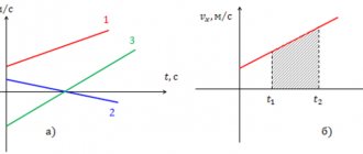
1) clock frequency
, which determines the maximum execution time for switching elements in a computer;
2) bit depth
, i.e. the maximum number of simultaneously processed binary bits. The digit capacity of MK is designated m/n/k/ and includes:
m - the capacity of internal registers, determines membership in a particular class of processors;
n — data bus width, determines the information transfer rate;
k - address bus width, determines the size of the address space.
For example, the i8088 MP is characterized by the values m/n/k=16/8/20;
3) architecture
. The concept of microprocessor architecture includes a system of commands and addressing methods, the ability to combine the execution of commands in time, the presence of additional devices in the microprocessor, principles and modes of its operation.
In the process of development, the MK architecture has undergone significant changes. The first MKs were built according to the so-called Princeton architecture (
von Neumann architecture) fig. 2.1, in which the memory for commands and data is shared. This architecture has its advantages - simplicity, the ability to quickly redistribute memory between command and data storage areas, etc. The disadvantage is time-sequential sampling from memory of commands and data transmitted over the same system bus, which limits the performance of the microcontroller. Nevertheless, due to its merits, the Princeton architecture not only dominated microprocessor technology for a long time, but also retained its position to the present day.
In Harvard Architecture
(Fig. 2.2) the command memory and data memory are separated, and each of them has its own bus for communicating with the processor.
Fig.2.1. Von Neumann architecture MK
At the same time, during data transfers to execute the current command, you can fetch and decrypt the next one, which increases the performance of the MK system. The implementation of the system is more complicated compared to the Princeton one (there are more buses in the system), and the memory utilization rate is lower. But in high-performance MCU systems and the internal structures of high-performance MCUs, Harvard architecture is widely used.
According to another architectural feature related to the nature of the command system, MKs are divided into:
- CISC - processors;
- RISC - processors;
- VLIW - processors.
CISC MKs have a so-called complete command system (Complex Instruction Set Computer), i.e. a large set of multi-format commands using many addressing methods. The CISC architecture is inherent in classical processors; due to the variety of instructions (the total number of instructions is 100...200), it allows the use of effective methods for solving problems, but, at the same time, it complicates the processor circuit and increases its cost and, in general, does not provide
maximum performance. They are characterized by the following features:
· Unfixed command length.
· Execution of operations such as loading into memory, arithmetic operations is encoded in one instruction.
· A small number of registers, each of which performs a strictly defined function.
Rice. 2.2. Harvard MP architecture
RISC MKs have a reduced command system (Reduse Instruction Set Computer), from which rarely used commands are excluded. The total number of teams is in the range of 50...100. The first RISC processors were developed in the early 1980s at Stanford and California universities in the USA. The simple architecture allows you to both reduce the cost of the MK and increase the clock frequency.
Characteristic features of RISC microcontroller:
· Fixed length of machine instructions (eg 32 bits) and simple instruction format.
· One instruction performs only one memory operation—read or write. There are no read-modify-write operations.
· A large number of general purpose registers (32 or more).
Many early RISC MCUs didn't even have multiply and divide instructions.
The command formats, at least the vast majority of them, are identical (for example, all commands are 4 bytes long), and the number of addressing methods used is sharply reduced. Data is typically processed with register or immediate addressing only. The number of processor registers has been significantly increased, which makes it possible to rarely access external memory, and this increases performance. The identity of command execution time cycles makes it easier to organize conveyor methods of information processing.
There are intermediate solutions between CISC and RISC processors, for example the AVR MK from Atmel, which are very popular among developers at present. They have Harvard architecture and a fairly developed, although truncated, command system. In particular, their arsenal includes up to 133 instructions, which corresponds to CISC. On the other hand, most instructions are executed in one clock cycle, in contrast to CISC MK with Princeton architecture, where a minimum of 12 clock cycles are required to execute one instruction. Therefore, if we assume that the execution of some CISC instructions will require the execution of up to 3 RISC instructions, the performance of the AVR MCU is more than 4 times higher than the performance of classic MCUs with Princeton architecture. In fact, AVR microprocessors have become an industry standard.
The latest to appear (less than 10 years ago) were VLIW processors (Very Long Instruction Word), the peculiarity of which is the use of very long commands (16 bytes or more). Individual fields of a long command define several micro-operations to be implemented, which can be executed in parallel in time in several operating units of the processor. Thus, a long command immediately defines a group of micro-operations. VLIW processors are considered promising for high-performance systems.
The wide variety of MKs produced does not allow us to consider them all within the framework of this course. Therefore, we will limit ourselves to considering the most popular Atmel microprocessors with CISC architecture MCS-51 and RISC architecture AVR.
The microcontroller (MK) is characterized by:
1) clock frequency
, which determines the maximum execution time for switching elements in a computer;
2) bit depth
, i.e. the maximum number of simultaneously processed binary bits. The digit capacity of MK is designated m/n/k/ and includes:
m - the capacity of internal registers, determines membership in a particular class of processors;
n — data bus width, determines the information transfer rate;
k - address bus width, determines the size of the address space.
For example, the i8088 MP is characterized by the values m/n/k=16/8/20;
3) architecture
. The concept of microprocessor architecture includes a system of commands and addressing methods, the ability to combine the execution of commands in time, the presence of additional devices in the microprocessor, principles and modes of its operation.
In the process of development, the MK architecture has undergone significant changes. The first MKs were built according to the so-called Princeton architecture (
von Neumann architecture) fig. 2.1, in which the memory for commands and data is shared. This architecture has its advantages - simplicity, the ability to quickly redistribute memory between command and data storage areas, etc. The disadvantage is time-sequential sampling from memory of commands and data transmitted over the same system bus, which limits the performance of the microcontroller. Nevertheless, due to its merits, the Princeton architecture not only dominated microprocessor technology for a long time, but also retained its position to the present day.
In Harvard Architecture
(Fig. 2.2) the command memory and data memory are separated, and each of them has its own bus for communicating with the processor.
Fig.2.1. Von Neumann architecture MK
At the same time, during data transfers to execute the current command, you can fetch and decrypt the next one, which increases the performance of the MK system. The implementation of the system is more complicated compared to the Princeton one (there are more buses in the system), and the memory utilization rate is lower. But in high-performance MCU systems and the internal structures of high-performance MCUs, Harvard architecture is widely used.
According to another architectural feature related to the nature of the command system, MKs are divided into:
- CISC - processors;
- RISC - processors;
- VLIW - processors.
CISC MKs have a so-called complete command system (Complex Instruction Set Computer), i.e. a large set of multi-format commands using many addressing methods. The CISC architecture is inherent in classical processors; due to the variety of instructions (the total number of instructions is 100...200), it allows the use of effective methods for solving problems, but, at the same time, it complicates the processor circuit and increases its cost and, in general, does not provide
maximum performance. They are characterized by the following features:
· Unfixed command length.
· Execution of operations such as loading into memory, arithmetic operations is encoded in one instruction.
· A small number of registers, each of which performs a strictly defined function.
Rice. 2.2. Harvard MP architecture
RISC MKs have a reduced command system (Reduse Instruction Set Computer), from which rarely used commands are excluded. The total number of teams is in the range of 50...100. The first RISC processors were developed in the early 1980s at Stanford and California universities in the USA. The simple architecture allows you to both reduce the cost of the MK and increase the clock frequency.
Characteristic features of RISC microcontroller:
· Fixed length of machine instructions (eg 32 bits) and simple instruction format.
· One instruction performs only one memory operation—read or write. There are no read-modify-write operations.
· A large number of general purpose registers (32 or more).
Many early RISC MCUs didn't even have multiply and divide instructions.
The command formats, at least the vast majority of them, are identical (for example, all commands are 4 bytes long), and the number of addressing methods used is sharply reduced. Data is typically processed with register or immediate addressing only. The number of processor registers has been significantly increased, which makes it possible to rarely access external memory, and this increases performance. The identity of command execution time cycles makes it easier to organize conveyor methods of information processing.
There are intermediate solutions between CISC and RISC processors, for example the AVR MK from Atmel, which are very popular among developers at present. They have Harvard architecture and a fairly developed, although truncated, command system. In particular, their arsenal includes up to 133 instructions, which corresponds to CISC. On the other hand, most instructions are executed in one clock cycle, in contrast to CISC MK with Princeton architecture, where a minimum of 12 clock cycles are required to execute one instruction. Therefore, if we assume that the execution of some CISC instructions will require the execution of up to 3 RISC instructions, the performance of the AVR MCU is more than 4 times higher than the performance of classic MCUs with Princeton architecture. In fact, AVR microprocessors have become an industry standard.
The latest to appear (less than 10 years ago) were VLIW processors (Very Long Instruction Word), the peculiarity of which is the use of very long commands (16 bytes or more). Individual fields of a long command define several micro-operations to be implemented, which can be executed in parallel in time in several operating units of the processor. Thus, a long command immediately defines a group of micro-operations. VLIW processors are considered promising for high-performance systems.
The wide variety of MKs produced does not allow us to consider them all within the framework of this course. Therefore, we will limit ourselves to considering the most popular Atmel microprocessors with CISC architecture MCS-51 and RISC architecture AVR.
What is the difference between a microcontroller and a microprocessor?
All computer functionality of a microprocessor (Micro Processor Unit - MPU) is contained on a single semiconductor chip. In terms of characteristics, it corresponds to the central processing unit of a computer (Central Processing Unit - CPU). Its scope is data storage, performing arithmetic and logical operations, and systems management.
The MP receives data from input peripheral devices, processes it and transmits it to output peripheral devices.
A microcontroller combines a microprocessor and the necessary supporting devices combined into one chip. If you need to create a device that communicates with external memory or a DAC/ADC unit, then you only need to connect a constant voltage power supply, a reset circuit, and a clock source.
CPU - microcontroller processor
Its task is to generate the address of the next command, select the command from memory and organize its execution. Main devices of the CPU: - ALU - arithmetic-logical unit - general purpose register block (RON)
ALU is a device that performs arithmetic and logical operations on data that comes from general purpose registers. RON - general purpose registers (32 RON in total, from R0 to R31), the main task of which is to exchange data between the ALU and memory cells.
Microcontroller devices
Each type of controller has its own peripheral devices that operate autonomously, i.e., independently of the central core. Once the peripheral has completed its task, it may or may not report this to the CPU. It depends on how it is programmed.
The MK may have the following devices:
- Analog comparator. Its main task is to compare the incoming (measured) voltage with the ideal one. If the measured voltage is higher than ideal, then the comparator produces a logical 1 signal (the device turns off), if lower, then a logical 0 (the device continues to work).
- Analog-to-digital converter (ADC). Measures analog voltage over a period of time and outputs it in digital form. Not everyone has MK.
- Timer/counter. It is a combination of 2 forms of timer and counter. The timer forms time intervals, and the digital counter counts the number of pulses coming from the internal frequency generator or signals from external sources. One of the representatives of the timer/counter operation can be PWM (pulse width modulator). It is designed to control the average voltage value under load.
- Watchdog timer. Its task is to restart the program after a certain period of time.
- Interrupt module. It informs the MK about the occurrence of an event and interrupts the execution of the program. After the event ends, resumes the interrupted program.
Not all of these peripherals are necessarily included in every MCU. There are other, less common devices.
What are microcontrollers - purpose and device
See also reviews and articles:
- What are microphone connectors: classification, where are they used?
- How to test a transistor with an inexpensive multimeter
- How to choose a microscope?
The rapid development of electronics is rapidly changing our lives, and we notice this, first of all, in the social sphere, the areas of communication (communication) and communication. The first thing that comes to mind in this regard is the computer, the Internet and cell phones. We are free to search for the necessary information and have the opportunity to contact the desired subscriber, regardless of our location. We can receive distance education and join groups based on professional, social or cultural interests. All this became possible largely due to the invention of the microprocessor and the creation of microprocessor systems. Other computer technology also helped.
And there are other manifestations of the progress of microelectronics, which are not so noticeable, but play an important role in our lives.
What is a microcontroller
Thus, microprocessors and microcontrollers are widely used in household appliances, automotive electronics, aerospace and military industries and, of course, in industrial production.
A microcontroller is a microelectronic programmable device designed to process information and control the exchange of this information as part of a microprocessor system (computer).
Why “microelectronic”? Because processors are manufactured using modern microelectronics technologies based on a semiconductor crystal. Information in a microprocessor system is transmitted by electrical impulses. One chip has a lot of things - digital ports, analog-to-digital converters for measurements, all sorts of timers, and so on.
What types of microcontrollers are there?
It is difficult to determine which specific classification of microcontrollers is the most acceptable, because today there are more than forty families and more than 300 varieties of this miniature device. Let's list some of them.
What types of microcontrollers are there:
- Microchip PIC,
- Atmel AVR;
- ATTiny26L;
- ATMega8515, etc.
Atmel AVRs have a main nuance - each command is executed in 1 or 2 clock periods. They can make several simple programs in the “graphical programming” Alghorytm Builder.
It is worth mentioning such a sub-variety as ARDUINO, the microboard of which is built on the basis of the ATMega168 controller, that is, this is the same AVR, but a bootloader, which allows you to flash it via USB and program it in a simplified SI, which was called Processing.
It costs a lot compared to a regular controller; the code generated by the Processing compiler is not very optimal in terms of volume and speed. And most importantly, programming for Arduino does not provide knowledge of what is happening inside the real controller.
What is a microcontroller (MK)? To put it simply, it is actually a whole computer in one chip! It’s just very simple in characteristics (compared to modern PCs, since there are microcontrollers that are clearly more powerful than the old Spectrum and even 486. And it’s designed to solve problems in various “embedded” systems.
How does a microcontroller work?
That is, in the microcontroller are:
- an arithmetic logic unit (processor) that performs calculations and logical operations;
- Random access memory (RAM)
- Program memory (Flash), which is analogous to a PC hard drive, it stores the firmware program;
- non-volatile memory (EEPROM), where the program can save data that will not disappear when the power is turned off. The program memory is also non-volatile, but the program cannot save data there during operation (in principle, this is possible, but this is not done due to the limited number of write-erase cycles (10,000 for AVR))
- I/O ports, which are used to communicate with the “outside world”. If in a PC the ports are standardized and each have their own purpose, then these are simply outputs that can be configured programmatically depending on the wishes of the device developer on the MK.
- Other peripherals, for example, an analog-to-digital converter (actually measures the voltage value at the input, outputting the result in digital form), an analog comparator (compares the voltages of analog signals and produces a value greater / less than 1 or 0), timers, which are used to measure segments time, delays and other functions.
- Also, many MKs have built-in interfaces UART (serial port), JTAG (protocol for debugging a program inside the controller), USB and others.
Purpose of microcontrollers
And now let's talk about the scope of MK. You just can't imagine it here:
- Use to replace complex logic circuits. If there are no performance requirements, because the program will still calculate your logical function, it may introduce a delay significantly greater than a circuit built on discrete logic elements (microcircuits of the K155, K176 series and similar).
- One example is, for example, a circuit that implements dynamic indication on seven-segment LED indicators. On logic elements, a 4-bit dynamic indication circuit looks something like this:
As you can see, work with sensors, as well as drives and lighting control is carried out using the C8051 microcontroller. And it, in turn, is connected to a PC, tablet or other device with a full-fledged operating system. - Application in various robotic devices, including unmanned aerial vehicles;
- For example, the quadcopter is driven by the “Crius MultiWii SE” board, which is built on the AVR ATMEGA328P microcontroller. It processes signals from sensors of inclination angles, acceleration, pressure, magnetic field (compass), and allows for flight stabilization
- Just different interesting gadgets, such as watches, thermometers, one example is the watch presented here:
- Control units for household appliances (washing machine, food processors, microwave ovens, etc.), audio equipment (adjustment from remote controls). also often used as control devices in voltage stabilizers. For example, relay stabilizers are mainly built on a microcontroller, which, by measuring the voltage presented at the ADC input, concludes how the transformer windings should be turned on so that the output is about 220.
- Various programmers and other devices act as interface converters from a PC to other devices. For example, K-Line adapter for diagnosing injection engines.
So, MK can be used for a wide variety of purposes.
The principle of operation of microcontrollers
AVR microcontrollers of the Tiny family are characterized by the presence of one or two timers. They affect Timer0 and Timer1. Typically, one of the timers has a simplified set of functions (Timer0), and the second has an expanded set of functions (Timer1). If there is only one timer in the MK, then in most cases it has an expanded set of functions. This timer is equipped with an advanced set of functions. In the ATtiny 26 microcontroller it is 8-bit, just like Timer0. List of functions that this node can perform:
- Countdown of time intervals
- Generating a counter overflow interrupt.
- Hardware generation Signal with pulse width modulation (PWM) (2 channels).
- Performs a comparison of the counter value with the preset values of the OCR1A, OCR1B registers and generates the corresponding interrupts when a match occurs.
- Possibility of clocking from both the system clock (fc) (synchronous mode) and the internal 64 MHz PLL circuit (fpck). (Asynchronous mode). Structurally, the processor is made in the form of one chip (sometimes several). The microcircuit consists of a plastic or ceramic housing, which contains a miniature semiconductor substrate (Fig. 1). All the electronic circuits of the microprocessor are “inscribed” with a laser on this substrate. The inputs and outputs of the circuit on the substrate are connected to metal pins located on the sides or bottom of the chip body.
Let's consider the simplest method - the counter counts in normal mode - cyclically due to overflow. Interrupts are also involved in comparison, for example, with the OCR1A register. In the overflow interrupt, we will turn on the OUT output by applying logic 1 to it. In the Timer1CompA comparison interrupt, we will turn off the output by applying logic 0 to it.
So, we will get a sequence of pulses that go with the same period (equal to the counter overflow period, which can be calculated as 256 / ft), where ft is the clock frequency of the timer. The pulse length will be proportional to the value in the OCR1A register, the larger the value, the later the output will turn off, the longer the pulse and the shorter the pause.
In fact, the method described is actually software PWM generation, Timer1 contains a hardware PWM modulator, which itself turns the outputs on and off under the described conditions. Interrupt signals are also generated, but usually when operating in PWM mode, timer interrupts are not used and are disabled in the settings of the control registers.
To enable a hardware PWM modulator, there is a corresponding flag in the control registers. When switching to PWM mode, the operation of the timer is slightly different from the standard mode. Here, by default, the timer does not count until it overflows, but up to the value that is written in the OCR1C register. When the values of TCNT1 and OCR1C are equal, the counter is reset to 0. This allows you to accurately set the pulse frequency; here it depends not only on the clock frequency, but also on the OCR1C value.
The presence of two comparison registers OCR1A and OCR1B allows you to get two PWM modulator channels (but with the same frequency). That is, you can easily control two loads of the same type, for example, independently change the brightness of two LED lamps.
It should be noted that the values of the OCR1A and OCR1B registers can range from 0 to the value of OCR1C. Of course, no one forbids writing there a value whose value exceeds the OCR1C register, but in this case we will have a signal at the output with a constant level and not a pulse sequence, since the value of TCNT1 will never reach the condition of equality with the comparison register, according to which there will be no signal at the output change.
The PWM modulator in the ATTiny 26 MK has both direct outputs OC1A, OC1B and inverse outputs OC1A, OC1B. At this level, the levels at the inverse outputs in PWM mode do not change simultaneously with the change in the levels of the direct outputs. The transition from 0 to 1 of the inverse pulse occurs one period of the timer clock frequency later than the transition from 1 to 0 on the direct output, and the reverse transition from 1 to 0 on the inverse output occurs, on the contrary, a period earlier than the transition from 0 to 1 on the direct output. The inclusion of direct and inverse outputs, as well as the order of signal changes on them, can be changed using control registers. The standard generation of a PWM signal by the ATTiny 26 timer is shown in the figure: It should be noted that the values in the OCR1A and OCR1B registers change at the moment the counter is reset. This is implemented in hardware using so-called buffer registers, that is, the program can change the value at any time, but it will be written to the comparison registers when the counter passes through 0; until this moment they are stored in a buffer.
conclusions
In short, in the modern world, almost all devices are in one way or another connected with devices such as a microcontroller and a microprocessor, which over many decades, since 1971, have been transformed from large transistor-based devices. It is impossible to imagine programming without them now. After all, all computing processes are based on them. They have also penetrated into the sphere of children's toys, which today, thanks to the development of microcontrollers, can boast robotic engineering for children based on the Arduino STEMbot.
Published: 2020-06-30 Updated: 2021-08-30
Author: Electronoff Store
SUITABLE PRODUCTS
- Microcontroller STM8L051F3P6, TSSOP-20 package 1 review
Buy
165 UAH
Code 15094
in stock
- Microcontroller AT49LV8011-90TC, TSOP-48 package 2 reviews
Buy
96 UAH
Code 15092
in stock
- Microcontroller with firmware for MasterKit NM8036 module 0 reviews
648 UAH
Code 5364
absent
- Microcontroller with MasterKit firmware for MP707 module 0 reviews
402 UAH
Code 5385
absent
- Microcontroller with firmware for MasterKit NT801D module 0 reviews
306 UAH
Code 5502
absent
Share on social networks
Comments on the article “What are microcontrollers - purpose and device”
- Leave your comment on the article...
Leave your comment
Error
What is needed to program a microcontroller
In order for the microcontroller to perform the necessary functions and solve certain tasks, it must be programmed.
The programming path goes through several stages:
- Before you start writing program code, you need to decide on your ultimate goal.
- An algorithm for the program is compiled.
- Direct writing of program code. The codes are written in C or Assembly language.
- Compiling a program, i.e. translating it into a binary or hexadecimal system of 1 and 0. This is the only way the MK can understand it.
- The compiled code is written to the controller memory.
- The MK is flashed using a programmer. They come in two connection types: via COM or USB port. The simplest and cheapest USBASP programmer.
- Testing and debugging of MK on a real device.
Radio amateurs sometimes get by without writing down the algorithm of the program on paper. They keep it in their heads.
Programming languages
Programming languages for microcontrollers are not much different from classical computer languages. The main difference is that MKs are focused on working with the periphery. The MK architecture requires bit-oriented instructions. Therefore, special languages were created for controllers:
- Assembler. Lowest level of language. Programs written in it are cumbersome and difficult to understand. But despite this, it allows you to fully reveal all the capabilities of the controllers and get maximum performance and compact code. Suitable mainly for small 8-bit MCUs.
- C/C++. Higher level of language. A program written in it is more understandable to humans. Today there are many software tools and libraries that allow you to write codes in this language. Its compilers are available on almost any MK model. Today it is the main language for programming controllers.
- An even more easy-to-understand and design language. But it is rarely used for MK programming.
- An ancient programming language. Today it is almost never used.
The choice of programming language depends on the tasks to be solved and the required quality of code. If you need compact code, then Assembler is suitable; for solving more global problems, the choice will be limited to C/C++.
WWW
As a rule, simple devices like a flasher or a timer are assembled on such MKs. These controllers had a monopoly in the post-Soviet space for a long time, and as a result, there are a huge number of Russian-language services and articles on the Internet dedicated to these MK models. When assembling a device, you often don’t even have to write the firmware, because it can easily be found on the Internet, even in several versions.
The second advantage is the built-in independent (from the clock generator) counters. Thanks to this fact, the family has established itself as the “brains” for frequency counters. I have a couple of these controllers in my workshop for a rainy day. The only downside is the high cost of the original programmers, called PICkit.
PICKIT3
There are many articles on the Internet on assembling worthy analogues of such programmers. But the whole point is that to build a programmer, what do you need? That's right, programmer. For this case, the Gromov programmer was developed. You don’t need almost anything to assemble it, and it works from the computer’s COM port. At the time of its development, the popularity of this MK series was high, and all PCs had COM ports. Nowadays all this is already a rarity, so you will have to overcome the entry threshold or fork out more money.
Continuation is available only to members
Option 1. Join the “Xakep.ru” community to read all materials on the site
Membership in the community during the specified period will give you access to ALL Hacker materials, allow you to download issues in PDF, disable advertising on the site and increase your personal cumulative discount! More details
Development environment
Today it is impossible to find a universal environment for programming MK. This is due to its internal structure and the presence of technical support for writing code into the controller’s memory.
Here are some programming environments:
- FlowCode is a universal graphical environment. It is programmed by constructing logical structures of block diagrams.
- Algorithm Builder. Also a graphical environment. But writing code is 3-5 times faster than in FlowCode. It combines a graphic editor, a compiler, a microcontroller simulator, and an in-circuit programmer.
- It combines Assembler and C/C++. The functionality of the environment allows you to independently flash the MK.
- Image Craft. Like the previous one, it supports Assembly and C/C++ languages. It includes a library that allows you to work with individual MK devices.
- A popular medium for hobbyists. It has a C-like language, but different from others. It is more understandable to humans. Supports libraries that contain drivers for connecting some platforms.
There are paid and free environments. When choosing a specific environment, you need to proceed from its functionality, programming language, supported interfaces and ports.
Basics of programming
Before you start programming the MK, you need to select a language. It's better to start with Assembler. Although it is quite complicated to understand, if you put in the effort and still understand its logic, then it will become clear what exactly is happening in the controller.
If assembler turns out to be difficult, then you can start with C. One of its strengths is that it transfers codes well from one type of MK to another. But to do this, you need to write everything down correctly, dividing the working algorithms and their implementations in the machine into different parts of the project. This will allow you to transfer the algorithm to another controller, redoing only the interface layer in which access to the hardware is written, leaving the working code unchanged.
Then proceed according to the following scheme:
- Choosing a compiler and installing the environment (more about them was written above).
- Launching the environment and selecting a new project in it. You will need to indicate the location. The shortest path must be chosen.
- Project setup. The classic action would be to create a makefile that contains all the dependencies. On the first page they also indicate the operating frequency of the MK.
- Setting up paths. You need to add the project directory to them. You can add third-party libraries to it.
- Formulation of the problem.
- Assembling the circuit. At this stage, you need to connect the USB-USART converter module to the same pins of the MK. This will allow you to flash the microcontroller without a programmer. You need to put on jumpers connecting LED1 and LED2. With this action we will connect LEDs 1 and 2 to pins PD4 and PD5.
- Write down the code.
- Adding libraries and headers with definitions.
- Main functions. The C language consists of only functions. They can be nested and called in any order relative to each other and in different ways. But they all have three required parameters: 1) return value; 2) transmitted parameters; 3) function body. Depending on the data, all returned or passed values must be of a certain type.
- Compiling and running emulation.
- Debugging the program.
After you have written a program in C, you can observe how and what happens in MK. This will help to build an analogy with assembly language programming.
Tips for novice microcontroller programmers
So that your first experience in MK programming does not end in failure and forever discourage you from doing this business, you need to follow some tips:
- Start by studying the periphery and its features.
- Each large task must be divided into as many small ones as possible.
- At the beginning of your journey, you should not simplify your life and use code generators, non-standard features, etc. things.
- It is necessary to study programming languages (C and Assembly).
- Read the Datasheet.
- Gather the necessary set of tools. This costs some money, but will pay for itself in time savings and quality of work.
It's never too late to become a radio amateur, whether you're 30 or 50. And it's not necessary to have a specialized higher education. Nowadays there is a lot of available information on the Internet, by studying which you can understand the structure of microcontrollers and learn how to program them.
Microcontrollers
This section is devoted to such a modern topic as microcontrollers . Currently, almost no modern device can do without microcontrollers. If you have any questions on the topic of microcontrollers , their programming, etc., then you can visit the forums: MK for beginners, AVR forum, PIC forum, Arduino and Raspberry Pi, STM32/ARM forum, programmers , peripherals, FPGAs, where competent specialists and forum participants will try to answer your questions.
Microcontrollers for Beginners:
- AVR microcontrollers for beginners. Part 1 - introduction to the AVR family
- AVR microcontrollers for beginners. Part 2 - programmers and firmware. Working with PonyProg
- AVR microcontrollers for beginners. Part 3 - working with CodeVision AVR
- Book on programming AVR microcontrollers
- Video course (8 lessons, plus tasks) on AVR with the author’s support topic on the forum
- Microcontroller training video for beginners
- AVR in C - easy?
- AVR in C - easy? Part 2
- AVR in C - easy? Part 3
- AVR in C - easy? Part 4
- Fuses of AVR microcontrollers - how and with what they are used
- Learning to create devices on microcontrollers: “traffic light”
- Learning to create devices on microcontrollers: “battery charge indicator”
- An ideal C program for MK, let's try to write
- The ideal C program for MK - continued
- Writing C programs in Code Vision AVR for controllers without RAM
- Timer/Counter for AVR for beginners
- PWM on Attiny13 microcontroller
- PWM controller on MK Attiny2313 (fan control)
- PWM controller on ATmega8515 microcontroller
- Brightness control (PWM) for LED driver or bicycle headlight
- PWM or PWM (Pulse Width Modulation) on AVR for beginners. Part 1
- PWM or PWM on AVR for beginners. Part 2 - software PWM
- Software PWM on STM8L
- Works MCP3421 ADC 18 bit with ATmega32 microcontroller
- Development board on AT89S52 or studying MK from scratch
- Counter with memory on Attiny2313
- Control of 595 shift registers using AVR via SPI
- Turning devices on and off with one button
- Turn devices on and off with one button
- Connecting LEDs to AVR
- mikroPascal for AVR. Lesson 1. Introduction
- mikroPascal for AVR. Lesson 2. ADC, UART and display
- mikroPascal for AVR. Lesson 3. UART again and also a little about interrupts
- mikroPascal for AVR. Lesson 4. Interrupts, interruptions and more interruptions. Timers
- mikroPascal for AVR. Lesson 5. Using OneWire. Built-in library
- mikroPascal for AVR. Lesson 6. Working with OneWire again. Expanded library
- mikroPascal for AVR. Lesson 7. Hardware PWM
- mikroPascal for AVR. Lesson 8. Software PWM
- Lesson on PWM (PWM) for mikroPascal for AVR
- Lesson on mikropascal for AVR.I2C
- AvrStudio 4. Library for AVR. Module for I2C or TWI
- Algorithm Builder. Lesson 1 - Introduction
- Algorithm Builder. Lesson 2 - About creating your first program
- Using USI interface to connect I2C peripherals to Attiny2313
- Working with I2C and SPI using the PCA2129T real-time clock as an example
- Several useful utilities for microcontrollers
- Library for managing multiple 1Wire devices in a point-to-point topology
- Expanding the number of ports of the PIC18 microcontroller via the SPI interface
- AvrStudio 4. CMSIS for AVR. Structure for GPIO
- PSoC. Chapter 0. Introduction. First example
- PSoC. Chapter 1. ADC
- PSoC. Chapter 2. UART
- PSoC. Chapter 3. DAC and UART RX line
- PSoC. Chapter 4 Timers and Global Interrupts
- Let's start working with FPGA or FPGA - it's easy. Part 1
- Let's start working with FPGA or FPGA - it's easy. Part 2
- Xilinx module template on VHDL and TestBench for testing
- FPGA internals
- FPGA. Just about the complex - Philosophy of writing configurations for FPGAs
- FPGA. Just about the complex stuff - Creating a project in Quartus II. Comparison of VHDL and Verilog
- QuickLogic QuickFeather Development Kits
- Let's start working with MSP430 microcontrollers from Texas Instruments
- Project of a virtual COM port for the STM32H107 development board
- SYS/BIOS: real-time operating system for MSP430 microcontrollers
Lessons on STM32, ARM:
- IAR and STM32 CORTEX M0. Part 0x00 (empty chatter and excuses)
- IAR and STM32 CORTEX M0. Part 0x01. Preparing the IAR platform
- IAR and STM32 CORTEX M0. Part 0x02, Let's start soldering!
- IAR and STM32 CORTEX M0. Part 0x03, Programming without a programmer
- IAR and STM32 CORTEX M0. Part 0x04 Automation of IAR firmware
- IAR and STM32 CORTEX M0. Part 0x05, GPIO - goes in and out...
- IAR and STM32 CORTEX M0. Part 0x06, Timers, PWM, interrupts
- ARM made easy (part 1)
- ARM made easy (part 2)
- ARM made easy (part 3)
- STM8. Lesson 1. ST Visual Develop environment settings
- STM8. Lesson 2. Controller clocking
- STM8. Lesson 3. Description of GPIO and SPL library
- STM8. Lesson 4. Setting up a timer 4. Timer interrupts
- STM8. Lesson 5. Quick setup of STVD environment for STM8S and STM8L
- STM8. Lesson 6. Project structure for STM8L and STM8S
- STM8. Lesson 7. Selecting and configuring a memory model
- STM8. Lesson 8. Assembly language inserts in Cosmic. Shifts in C
- STM8. Cosmic compiler error "FlexLM No such feature exists"
- STM32 start with CMSIS
- STM32 easy and fast start with CooCox CoIDE
- ARM. STM32 quick start
- STM32. Lesson 1. Selecting a development board
- STM32. Lesson 2. I/O Ports
- STM32. Lesson 3. UART
- STM32. Lesson 4. Basic timers
- STM32. Lesson 5. Connecting the WH1602 LCD display
- STM32F4. Lesson 1 - LED Control
- STM32F4. Lesson 2 - Pressing a Button
- STM32F4. Lesson 3 - Digital Outputs
- STM32F4. Lesson 4 - Digital Inputs
- STM32F4. Lesson 5 - working with ADC
- STM32F4. Lesson 6 - working with the ST7783 display
- STM32F4. Lesson 7 - Graphics library for the ST7783 display
- STM32F4. Lesson 8 - ST7783 Display Font Library
- STM32F4. Lesson 9 - Touchscreen ADS7843
- STM32F4. Lesson 10 - Software Timer and Counter
- STM32F4. Lesson 11 - Random Number Generator
- STM32F4. Lesson 12 - UART
- STM32F4. Lesson 13 - Working with an SD card
- STM32F4. Lesson 14 - ADC using DMA
- STM32F4. Lesson 15 - Low Level SPI
- STM32F4. Lesson 16 - Working with the MAX5250 DAC via SPI
- STM32F4. Lesson 17 - Controlling the LIS302DL via SPI
- STM32F4. Lesson 18 - Low Level I2C
- STM32F4. Lesson 19 — Working with EEprom M24C02 via I2C
- STM32F4. Lesson 20 - Displaying an image from an SD card
- STM32F4. Lesson 21 - ADC in Group Mode
- STM32F4. Lesson 22 - System Check
- STM32F4. Lesson 23 - Working with DAC
- STM32F4. Lesson 24 - Working with DAC via DMA
- STM32F4. Lesson 25 - Working with PWM
- STM32F4. Lesson 26 - Transferring ADC data to PC
- STM32F4. Lesson 27 - Connecting the OV9655 Camera
- STM32F4. Lesson 28 - Working with external interrupts
- STM32F4. Lesson 29 - Working with a PS2 keyboard
- STM32F4. Lesson 30 - Working with a PS2 mouse
- STM32F4. Lesson 31 — Using USB-OTG as a virtual COM port
- STM32F4. Lesson 32 — Using USB-OTG in MSC_HOST mode
- STM32F4. Lesson 33 - Working with the SSD1289 display
- STM32F4. Lesson 34 — Connecting a 16x2 character LCD display (HD44780)
- USB FLASH. Introduction and Part 1 - Working with the AT45DB161D
- USB FLASH. Part 2 - USB Peripherals in STM32F0
- USB FLASH. Part 3 - Final. SCSI protocol
- FAT32 to STM32
- Text command control (USART on STM32)
- Handling a custom button press using external interrupts
- Option to use packed time format in STM32
- Connecting a matrix keyboard to STM32F4Discovery
- Matrix keyboard library for STM32F4 Discovery
- Connecting HD44780 display to STM32 in CubeIDE (HAL)
- HD44780 library 4 lines x 20 characters for STM32
- Lighting up on TLC5940
- IAR EWARM. STM32F030F4P6. The microcontroller is not listed...
- STM32F030. Non-blocking I2C implementation
- Universal board based on STM32F405
- Nucleo-F411RE USB-ADC
- Working with LabVIEW using the STM32 as an example
AVR Lessons (BASCOM-AVR):
- Lesson 1. What is an AVR microcontroller?
- Lesson 2. AVR microcontroller programmer
- Lesson 3. Development board for AVR microcontroller Attiy13
- Lesson 4. Output ports in the Attiy13 microcontroller
- Lesson 5. Programming AVR microcontrollers
- Lesson 6. First design on the AVR microcontroller
- Lesson 7. Working with the LCD indicator on the HD44780 controller and its analogues
- Lesson 8. Entering information into MK. Connecting the button to the BASCOM-AVR MK
- Lesson 9. Working with ADC using the example of ATtiny13 in BASCOM-AVR
- Lesson 10. Working with the UART interface
- Lesson 11. Working with the DS1307 real-time clock chip
- Lesson 12. Working with a computer PS/2 keyboard in BASCOM-AVR
- Lesson 13. Hardware PWM on a microcontroller
- Lesson 14. Software UART in BASCOM-AVR
- Lesson 15. Working with the DS18B20 temperature sensor in BASCOM-AVR
- Lesson 16. Working with an encoder in BASCOM-AVR
- Lesson 17. Using the bootloader in BASCOM-AVR
- Lesson 18. Working with the display of Nokia 3310
- Lesson 19. Working with ultrasonic distance sensor HC-SR04 in BASCOM-AVR
- Lesson 20. Connecting a seven-segment indicator using three wires (74HC595)
- Lesson 21. BASCOM-AVR and Arduino
Circuits and devices on microcontrollers:
- Mini digital soldering station
- DIY digital soldering station DSS-1
- Digital soldering station 4 in 1 (DSS-2.1)
- Station for mounting and dismantling BGA and other SMD radio components
- Charger-analyzer of NiMh/NiCd batteries
- Intelligent NiMh/NiCd battery charger
- AA battery tester
- 12V battery charge status indicator
- Two microcontroller power regulators
- Autolight - control of external car lighting devices
- Onboard tachometer on PIC16C84
- Cycling computer based on PIC16F628A and 4-digit LED indicator
- DIY cycling computer
- Timelapse of growing microgreens on Onion Omega 2+
- Wi-Fi modules ESP8266 and AVR microcontroller
- MK communication using RF modules
- Radio communication between two microcontrollers using RF modules
- Radio relay on module NRF24L01
- Communication interface between GSM module SIM300 and AVR ATmega32 microcontroller
- Sending and receiving SMS using GSM module SIM300
- How to connect a microcontroller and a computer via RS-232
- Radio control of three loads on “RF modules” using microcontrollers
- Radio control device for 12 commands
- Radio control device (radio key) for 3 commands
- Remote control device for 12 high-power commands
- Electronic scales based on HX711
- Ultrasonic water level control using 8051 microcontroller
- Ultrasonic range finder
- Mini radar, speed meter
- Bluetooth communication between STM32 and Android
- DIY GPS receiver on the EB-500 and AVR module
- Portable GPS Data Logger
- Accelerometer ADXL345
- Accelerometer and gyroscope MPU6050
- Alcohol vapor concentration tester for AVR
- Simple electronic compass
- The simplest Laundromat
- Intelligent Laundromat
- One bill acceptor and four attractions
- Simple DIY vending machine
- Practical implementation of a multi-channel phase controller on Attiny2313
- Pairing the 830 Series Digital Multimeter with a Computer
- Electronic combination lock on ATmega8
- Combination lock on PIC16F628A
- Key location indication (Part 1)
- Key location indication (Part 2)
- Code lock
- Intercom and hub
- RFID transponder reader TIRIS from Texas Instruments
- Electronic key reader iButton (DS1990) on MK ATtiny2313
- Electronic lock with iButton keys
- Security device with iButton keys and shock sensor
- Motion sensor on a PIC microcontroller using a PIR sensor
- Security device with telephone line notification
- Security device "Laser tripwire"
- Multi-command remote control device for pyrotechnic shows
- Autonomous reset module
- 4-channel load controller with UART control
- Controller of 8 loads on ATtiny13 with UART control
- USB I/O device on PIC18F4550 with 16 digital I/O and 8 analog inputs
- Data logger (analog data recorder)
- I/O device
- USB Device
- COM terminal
- Connecting and starting the motor from FDD (JCM5044)
- A simple tester for unipolar stepper motors on ATtiny2313 and ULN2004
- Microstep driver from an old printer on an ATmega32 microcontroller
- Control of two stepper motors via UART
- Engine speed sensor for controller
- Development board for devices based on Atmega8/48/88/168/328 MCUs
- Development board for ATtiny13/15 microcontrollers
- Universal basis for a controller with a graphical interface on ATmega8 with an OLED display
- Simple development board based on ATTINY2313
- Development board AT90USB162
- PIC16F877A - Development board
- Development kit based on PIC18F4520 microcontroller
- Universal development board for AVR
- Control of 15 pins with one PIC microcontroller input
- Display and keyboard driver TM1638
- Connecting PS/2 keyboard to PIC
- Connecting PS/2, AT keyboard to Attiny2313 microcontroller
- Interface board for connecting a PS2 keyboard with an LCD display on a PICAXE MK
- Keyboard Morse code sensor (PS/2 and PIC16F628A)
- ABCom - ATmega1284P computer
- Electronic accessories for the game STALKER
- Wait for it! - 80s game
- Electronic game “LED Thimbles”
- Economical dice on PIC12F629
- Electronic dice on ATtiny 2313
- Game console on STM32 and LCD Nokia 5110
- Game video console on AVR AVGA
- Button controller for the game Brein Ring v2.0
- USB joke
- USB joke 2
- Defuse the Bomb Game
- Steering wheel, joystick and gamepad with feedback (Force Feedback)
- Microcontroller virus and antivirus
- USB Password Keeper
- Why are some microcontrollers more reliable than others?
- ATmega8 TQFP to DIP adapter
- Auxiliary modules for development boards
- Overclocking ATmega328 (30 MHz)
Lighting, LED, LCD and LCD:
- Multimedia device
- Simple touch screen interface on PIC
- Touch module on AVR
- Simple touch sensor on AVR
- We work with LCD. Part 1
- We work with LCD. Part 2
- Winstar LCD WH1602B
- Review of IPS display 80x160 pixels with ST7735 controller
- Review of 128x160 pixel display with ST7735 controller
- Connecting and using LCD Nokia 3310 (5110) to an AVR microcontroller
- Connecting a display from an HP LaserJet P2055 printer to a microcontroller
- Connecting a display from a Mercury 130K cash register to a microcontroller
- Connecting the display from the Elwes-Micro cash register to the microcontroller
- Negative voltage generator for display 1602 and similar
- A short test of the OLED display Winstar WEH001602ALPP5N
- We connect LCD from Siemens C75 and ME75 to STM32
- Working with LPH8731-3C display from Siemens phones
- Features of working with the LPH9157-2 display
- Library for LPH9135 display
- Library for character display based on HD44780
- TFT display 3.2 open source
- Connecting Nokia1616 display to BASCOM-AVR
- Connecting a 128x64 KS0108 graphic LCD display to AT89C52
- HD44780 LCD to UART adapter
- Information display device on a 16×2 LCD display with HD44780 controller
- Electronic tag with LCD on a microcontroller
- Connecting the ST7565 LCD display to the MSP430 microcontroller
- Connecting a monochrome display on ST7565 to STM32
- SSD1331 RGB OLED display
- Fiber optic LED lamp on ESP
- Software implementation of the TM1640 control interface on ATmega
- An advisor in your pocket
- No LCD driver - just a calculator!
- Do-it-yourself electronic reader on the ATmega32 microcontroller
- Connecting a seven-segment indicator via UART to ATtiny13
- Dynamic indication on 7-segment LED indicators with programmable brightness control
- Once again about dynamic indication on LED indicators
- Connecting a 4-digit LED indicator to a total of 4 microcontroller ports
- Controlling RGB spotlights
- A simple flasher on an RGB LED using the ATtiny2313 (ATtiny13) microcontroller
- Controlling WS2813 Addressable LEDs with ATtiny
- RGB LED control
- RGB lighting for the kettle
- Creeping line on PIC16F877 on 20 matrices 8x8 or 160x8 pixels
- Ticker 8×80 LED on PIC16F628
- Ticker 8×80 with typing on the keyboard (PIC16F628)
- Creeping line on PIC controller
- Ticker on ATmega168
- LED strip controller on ATtiny13a
- LED garland on a microcontroller
- Simple LED garland on MK Attiny13
- POV - LED bicycle wheel lighting on MSP430
- Ticker with mechanical scanning
- DMX512 Controller for 40 channels
- PixelPOI
- LED matrix – MOJET
- Fade Out effect for LED using PWM (PIC)
- 3-channel PWM regulator on Attiny2313
- Multichannel phase regulator on ATtiny2313
- PWM controller on AVR
- Backlight brightness control on BH1750 sensor
- DIY traffic light
- A device for simulating traffic light operation on a PIC16F84A microcontroller
- Traffic light on PIC12F629 with the “wrong” program
- Traffic light on ATtiny13
- Simulation of a traffic light
- LED control on MK Attiny13
- Burning candle effect on ATTiny
- ADC on TINY13 and 16 LEDs
- New Year's night lamp made of RGB LEDs on the LaunchPad MSP-EXP430 board, controlled by an IR remote control
- Night light on a microcontroller
- IR remote control on MSP430 Launchpad
- Refinement of the Chinese headlamp
- LED lamp with PWM and timer
- Chandelier controller with 6 lamps
- Dual Channel Light Cord Adapter
- Flexilight Dual Color Light Cord Controller
- Pimp up your monitor. Build an interactive backlight
Audio:
- Whistling analyzer on Cortex-M4 or switching on the load by whistle
- Transmitting audio over a radio channel using the Speex codec
- Visualization of audio signal on Nokia 3310 LCD
- Audio spectrum analyzer on Atmega32
- Simple SD audio player
- MMC/SD WAV stereo player on ATmega32 with TV remote control
- SD WAV player with UART control
- Video playback on Nokia color LCD using Atmega32 8-bit AVR microcontroller
- Second life Creative Sound Blaster
- DIY MP3 player
- Playing notes on the PIC
- Playing audio on PIC
- Piano on PIC18F4550 microcontroller
- Echo effect on the Atmega32 microcontroller
- MMC/SD voice recorder on PIC16F877A
- Musical bell with secret button
- Musical call on MK Attiny13
- Musical call with the ability to change melodies without using a programmer
- Musical bell that can do it all (Z80)
- Door bell
Clocks and timers:
- Talker mp3. Tube clock
- Clock on gas-discharge indicators
- Clock on gas-discharge indicators V2.0
- Nixie Clock "King Size"
- Electronic alarm clock with gas-discharge indicators and MK
- IV-11 - watch with effects
- Clock on gas-discharge indicators with ATmega8
- Steampunk clock with gas discharge indicators
- Clock on VLI indicator IV-18
- Clock on the IV-18 indicator
- Correct clock on IV-18
- Radio, oh radio! And also IN-18
- IV-9. Clock, effects, pain and something else
- Making LED clock CxemWatch-v1 on ATmega328p
- Wristwatches on GRI (based on the Bars project)
- Multifunctional thermostat clock with remote control
- Musical clock with thermometers on PIC16F873A
- Chess clock - souvenir
- Multifunctional LED wristwatch
- Talking clock
- Clock/calendar on MK ATTiny2313 and RTC DS1305
- Clock ATtiny 2313, DS1302, TM1637 in assembler
- Clock on DS3231 and AVR microcontroller
- Clock on PCA21125 and AVR microcontroller
- Clock – daily timer with time correction
- 4 MHz quartz clock
- Clock on PIC16F877A
- Clock on PIC16F628A and FYQ3641A
- Compact watch with LED indicators
- Clock on a PIC microcontroller
- Watches with automatic brightness adjustment, touch buttons, etc.
- Clock on Attiny2313
- LED clock on Attiny2313 and DS1307
- Clock on ATtiny2313, DS1307 and LCD indicator 8*2
- Multi-function clock on AVR
- Alarm clock radio
- Alarm clock with thermometer
- Clock - calendar
- Talking clock - thermometer with calendar
- Digital clock on RTC DS12C887 and 8051
- RTC on STM8L-Discovery
- Library for working with the I2C bus and the PCF8583 real-time clock
- Clock on PCF8523 and AVR microcontroller
- Detonator Clock
- Binary clock on ATmega8
- Simple binary clock
- USB hit counter on AVR ATtiny25 microcontroller
- Automatic call system for AVR
- Time relay
- Timer 0…9999 seconds for exposing photoresist on ATtiny13
- Household timer on a PIC microcontroller
- Simple timer on PIC16F84A
- Timer on PIC
- Countdown timer on MK Attiny2313
- Countdown timer on MK ATmega8 + LCD 8x2 or 16x1
- 0-9999 seconds countdown timer on PIC12F683
- Multifunctional cyclic timer
- We install a multifunctional cyclic timer in the case
Temperature measurement, thermostats and thermostats on microcontrollers:
- Weather station on STM32
- Indoor weather station
- WiFi ESP8266 - a new step in the design of home devices with a wireless interface
- BME280 sensor data exchange with PC
- Wireless temperature and humidity meter with USB interface
- Humidity and temperature meter
- Temperature and relative humidity sensor with adaptive brightness control
- Simple temperature meter
- LCD thermometer
- USB thermometer
- Bluetooth thermometer
- Bluetooth thermometer on AVR (Arduino)
- Thermometer on PIC
- Thermometer on SE97B sensor and AVR microcontroller
- Digital thermometer on LM75AD sensor
- Connecting the DS18B20 ambient temperature sensor to the microcontroller
- Thermometer on DS18B20
- Thermostat with digital temperature sensor
- Dual digital thermometer on ATmega8 and DS18B20
- Simple thermometer for home with two sensors DS18B20
- Thermometer on MK Attiny13 and sensor DS18B20
- Unusual thermometer on ATtiny13 and DS18B20
- Decorative thermometer on a microcontroller
- Thermometer for AT89C2051 and DS18B20
- Universal two-channel thermometer for AVR
- Multipoint thermometer
- Thermometer on STM8L-Discovery
- XControl
- LAN Control - remote control system via local network, Internet and remote control
- Electronic thermostat and temperature alarm on PIC16C84
- Thermostat on PIC16F877A and LCD NOKIA 3310
- Simple thermostat
- Thermostat with preset 4 control temperatures for room thermometer
- Thermostat on PIC
- Programmable thermostat
- Barometer on AVR
- Clock, thermometer, thermostat, alarm clock, remote control system
- Clock + thermometer on PIC16F628A and LED indicators
Measurements, generators:
- 30V voltmeter on MSP430
- Multichannel remote voltmeter
- Small-sized frequency meter - digital scale up to 200 MHz with LCD display
- Frequency counter up to 16 MHz on a microcontroller
- Homemade oscilloscope on an AVR microcontroller
- Oscilloscope probe for ATmega8
- Digital LCD Oscilloscope
- USB oscilloscope
- Signal generator on MK ATtiny2313
- Functional DDS generator
- DDS generator
- Color determinant
- Digital dosimeter Gamma_1
Programmers, MK recovery, firmware:
- Clone AVR JTAG ICE
- Chinese JTAG ICE for AVR and driver installation
- PICkit 2 clone
- PURPIC, portable clone of PICkit2
- Simple USB PIC programmer
- The simplest programmer for PIC
- Simple PIC controller programmer using PicPgm
- Programmer for PIC controllers
- Saving Calibration Constant for 12F629 and 12F675 PIC Controllers
- How to make a simple programmer for PICs and AVRs
- Programmer for microcontrollers AT89C51/52/55
- Simple programmer
- USBasp - USB programmer for Atmel AVR microcontrollers
- Improvement of the USBasp programmer
- VUSBTiny programmer
- USB programmer for parallel Flash and EEPROM memory chips
- USB programmer for parallel Flash and EEPROM memory chips. Continuation
- Universal USB programmer for AVR MK, I2C EEPROM and SPI Flash 25ХХ
- Universal USB programmer
- ZIF SOIC adapter for programmer
- Universal adapter-programmer
- Universal adapter for Atmel STK500
- Compact programmer USBTiny-MkII SLIM (clone AVRISP-MKII)
- Programmer ATtiny84 USBtiny AVR ISP
- AVR programmer ULTI-SP
- USB programmer for AVR and AT89S microcontrollers, compatible with AVR910
- Gromov programmer for ATmega8A-PU
- AVR programmer on PIC
- Universal programmer
- Fixing AVR fuzz
- Atmel microcontroller revitalization device
- SinaProg + ATmega328P fixing fuse firmware
- Programmer for KR573RF5
- Optocoupler module for in-circuit debugging and SPI programmers
- In-circuit programming and debugging of Microchip microcontrollers
- Programming AVR microcontrollers in Ubuntu
- Programming AVR microcontrollers in Ubuntu-2 (GUI)
- STM32F4DISCOVERY: Working with ARM Cortex M4