Frequency converters are technical devices that convert input network parameters into output parameters at various frequencies. Modern AC inverters have a wide frequency range.
The asynchronous frequency converter is designed to convert mains 3- or 1-phase alternating current f 50 Hz into 3-phase or 1-phase f 1 - 800 Hz.
Manufacturers produce electro-induction frequency generators, which are of the following design:
- asynchronous electric motor;
- inverters.
Frequency generators are often used to smoothly regulate the rotation speed of an asynchronous motor (IM) by generating specified network parameters at the output of the frequency generator. In the simplest cases, adjustment of f and U is performed with the corresponding V/f relationship; in more sophisticated inverters it is implemented as vector control.
An electronic frequency converter is a construct that consists of elements:
- rectifier converting I into Iconst;
- an inverter that converts Iconst into I with the required frequency and amplitude.
Output thyristors (transistors) serve to provide the necessary current to power the motor.
For correction Uout. Another time, a choke is placed between the frequency converter and the electric motor, and a filter is installed to reduce interference.
Classification of frequency converters
According to the type of supply voltage, frequency converters are divided into types:
- single-phase;
- three-phase;
- high-voltage devices.
The main task of a frequency converter can be formulated as follows: transferring the working process to an economical mode by controlling the speed and torque of the motor, according to the specified technical parameters and the nature of the load.
In this case, the digital display of the device shows such system operating parameters as:
- the value of I and U of the engine;
- output values of frequency, speed, power and torque (f, v, P and M);
- displaying the status of discrete inputs for regulating the speed of rotation of the IM shaft and remote control of the system;
- duration of operation of the frequency converter itself.
According to the area of use, the types of inverters are:
- industrial use with power up to 315 kW;
- Inverter with vector control with power up to 500 kW;
- for controlling mechanisms with pump-fan type load (P 15 - 315 kW);
- frequencies for cranes and other lifting structures;
- for use in explosive environments;
- VFDs installed directly on the electric motor.
Vector control
The elevator car must be perfectly positioned in height - the permissible error is usually a few millimeters. Such precision of movement can only be achieved using vector control, so a prerequisite for a frequency converter is the ability to operate in vector mode with speed feedback. The inverter must provide not only the appropriate settings, but also inputs for the encoder mounted on the motor shaft. With the correct vector mode setting, the elevator movement will be smooth and positioning will be as accurate as possible.
Frequency converter structure
The structure of a modern inverter is built on the principle of energy conversion and includes a power and control component. The first, as a rule, is performed on thyristors or transistors, which play the role of electric switches. The control unit is implemented on microprocessors. Using keys that open and close circuits, it allows you to quickly solve many diagnostic, protection, and control tasks.
According to the principle of operation, frequency converters are of two types:
- with the presence of an intermediate DC link;
- with direct connection.
All of them have a number of advantages and disadvantages that determine the scope of effective use of each of them.
Braking system
Smooth braking is ensured by operating the inverter in vector mode, while the released energy is converted into heat using a braking module and a braking resistor. The power of the braking resistor depends on the required braking torque, braking duration and the operating cycle of the elevator.
When the elevator car stops, the frequency converter sends a signal to the electromagnetic brake, which locks the motor shaft. The brake must be normally braked, that is, in order to be able to rotate the motor rotor, power must be supplied to the brake with a rated voltage.
Direct frequency converters
They belong to the earliest devices with a simplified power unit, which is a rectifier based on thyristors.
The control system turns on the group thyristors and connects the motor windings to the power supply. Direct - this is a reversible thyristor frequency generator. Its main advantage is that it connects directly to the network without additional devices.
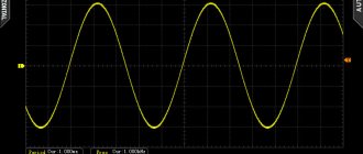
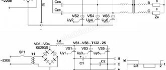
In this way, it turns out that the U out frequency generator is formed from truncated segments of the U out sinusoids. The figure shows an example of a formed Uout for one of the load phases. 3-phase sinusoidal components Uа, Uв, Uс are supplied to the thyristor input. The voltage Uout is represented by a non-sinusoidal “sawtooth” shape, which in approximated form looks like a sinusoid (thick curve). The drawing shows that the frequency U out cannot be equal to or exceed the power supply frequency. Therefore, the control range of the electric motor rotation speed is small (less than 1: 10). Limiting limits do not make it possible to use such frequency converters in sophisticated VFDs. The latter are designed for a wide range of indicator adjustments.
The use of thyristors increases the complexity of the control system, and therefore the cost of the frequency converter increases.
The output “truncated” sinusoid of the frequency generator is a source of high-frequency harmonics, causing additional losses in the electric motor, overheating of the electric machine, reduction of torque, and noise in the power supply network that interferes with operation. The use of compensating devices increases the price, weight, size, and reduces the efficiency of the entire system.
Nevertheless, direct frequency converters delight users with their certain advantages. These include:
- sufficiently high efficiency achieved by one conversion of electricity;
- operation in various modes, including with energy recovery into the network;
- reliability, relative cheapness, complete controllability and convenience;
- availability of unlimited capacity expansion of the system;
Such circuits are used in electric drives produced in previous years. In new designs they are not developed in practice.
How is the frequency converter connected?
If we consider the installation of a frequency converter schematically, then the whole process comes down to connecting the contacts of the device itself, the electric motor and the control fuse block. It is enough to connect the wires of all elements, connect the engine to the network and start it.
At first glance, there is nothing complicated about this, but, in fact, the installation procedure has some of its own nuances:
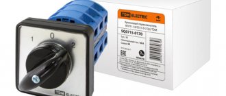
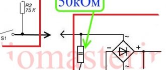
It is very important that a fuse is installed in the circuit between the frequency converter itself and the power source. It will allow you to promptly turn off devices in case of voltage surges, maintaining their functionality
It is noteworthy that when connecting to a three-phase network, it is necessary that the fuse itself is also three-phase, but has a common disconnect lever. This will make it possible to turn off the power on all phases at once, even if only one has a short circuit or overload. If the converter is connected to a single-phase network, then the fuse must be single-phase. In this case, when making calculations, it is necessary to take into account the current of only one phase, but multiplied by 3. It is always worth remembering that the instructions for almost any converter indicate the requirements and standards for its installation. You need to familiarize yourself with them before starting work. The phase outputs of the frequency converter are connected to the contacts of the electric motor itself. In this case, depending on the voltage of the frequency converter, the motor windings may have a “star” or “triangle” formation. There are usually two voltage values marked on the motor housing. If the frequency driver corresponds to the smaller one, then the windings are connected in a “star”, if the larger one corresponds to a “triangle”. All this information is usually printed in the instructions. Almost every frequency converter comes with a remote control panel. It is not a mandatory element of the circuit, because the device itself also has its own controls, but it can significantly simplify the work with the equipment. The remote control can be mounted at any distance from the frequency generator. This is usually done as follows: frequency converters that have a low degree of protection are located away from the engine, and the remote control itself is taken directly to the workplace near the equipment.
An equally important stage in installing a frequency converter is its test run. It works according to the following scheme:
- After connecting all elements of the system (fuse, control panel, frequency converter, motor), it is necessary to move the handle on the control panel to the active position by several degrees.
- Switch the fuse switches to the “ON” position. After this, the indicator lights on the frequency converters should light up, indicating that the equipment is connected correctly, and the motor should begin to rotate slowly.
- If the motor shaft begins to rotate in the opposite direction, it is necessary to reprogram the frequency converter itself for reverse movement. Almost all modern devices support this function.
- Move the control handle gradually and monitor the engine operation - the shaft speed should increase as you move the handle.
If no problems were found during the test run, then you have done everything correctly and the system can be included in the workflow.
Frequency converters with DC link
These are devices made using a transistor or thyristor circuit. However, their main distinguishing feature is that the correct and safe operation of the frequency generator requires the presence of a constant voltage link. Therefore, to connect them to an industrial network, a rectifier is required. Typically, complete equipment is used, consisting of a frequency converter and rectifier, controlled by one control system.
The inverter of this group uses a two-stage conversion of electricity: sinusoidal U input with f = const is straightened in the rectifier (V), filtered by a filter (F), smoothed, and then re-converted by the inverter (I) into U ̴. Due to the two-stage conversion of electricity, the efficiency decreases and the weight and size indicators slightly deteriorate in comparison with frequency converters with direct coupling.
To create a sinusoidal U ̴ self-controlled frequency converters. They use an advanced thyristor and transistor base as the key base.
The main advantage of thyristor converter equipment is the ability to operate with large network parameters, while withstanding continuous load and pulsed influences. The devices have higher efficiency.
Frequency converters based on thyristors today are superior to other high-voltage drives, the power of which amounts to tens of MW with U out from 3 to 10 kV and more. However, their price is correspondingly the highest.
Advantages:
- highest efficiency;
- possibility of use in powerful drives;
- reasonable cost, despite the introduction of additional elements.
Specific parameters
Specialized frequency converters for elevators use special control parameters, for example the following:
- elevator speed (m/s)
- motor pulley diameter (mm)
- mechanical reduction ratio (in case of using a motor with a gearbox)
- load inertia (%) – this parameter is determined by the mass of the elevator car
- elevator car acceleration (m/s2)
In addition, the converter must be “able” to accurately measure motor parameters and perform auto-tuning of the system under load. Also, the inverter for an elevator should have advanced settings for torque, speed, slip and protection.
Operating principle of the frequency converter
The fundamental drive is determined by a double conversion inverter. The principle of operation is to:
- input variable toxinusoidal type 380 or 220V is rectified by a block of diodes;
- then filtered by capacitors to minimize voltage ripple;
- then the voltage is supplied to microcircuits and transistor bridges, which create a 3-phase wave from it with set parameters;
- At the output, rectangular pulses are converted into sinusoidal voltage.
Caring for the Transducer
To extend the service life of the inverter, you should take proper care of it:
- Monitor the accumulation of dust on the internal elements and promptly clean the device using a compressor.
- Make sure that the components used in the mechanism are working properly and replace them if the need arises.
- Maintain adequate operating temperature (no more than +40°C) of the mechanism and voltage level on the control bus.
- Regularly (at least once every 3 years) update the layer of thermal paste on the power components of the device.
- Maintain moderate humidity levels if possible.
How to connect and configure a frequency converter?
The general connection diagram for an asynchronous electric motor using a frequency converter is, in principle, not complicated, since all the main wiring is contained in the device housings. For a techie with practical knowledge, understanding it will not be difficult. In the circuit, a place is allocated for the converter immediately after the circuit breaker with a rated current equal to the rating of the electric motor. When installing the converter into a 3-phase network, it is necessary to use a three-pole circuit breaker that has a common lever. In case of overload, this will allow you to instantly disconnect all phases from the power supply network. The operating current must be equal to the current of one phase of the electric motor. For single-phase power supply, you should choose a circuit breaker with triple the current value of one phase.
In all cases, the inverter must be installed with circuit breakers connected to the neutral or ground wire.
In practice, setting up a frequency converter means connecting the cable cores to the visible contacts of the electric motor. The specific connection is determined by the nature of the voltage generated directly by the frequency converter. For 3-phase networks at industrial facilities, the electric motor is connected in a “star” - this circuit implies a parallel connection of the winding wires. For domestic use in single-phase networks, a “triangle” circuit is used (where U out does not exceed U nom by more than 50%).
The control panel must be located where it will be comfortable to use. The connection diagram for the remote control is usually shown in the user manual for the frequency converter. Before installation, before power is applied, the lever must be moved to the “off” position. After this, the corresponding indicator light should light up. By default, to start the device you need to press the “RUN” key. To smoothly increase the speed of the electric motor, you need to slowly turn the remote control handle. When rotating in reverse, you must reset the mode using the reverse button. Now you can move the handle to the working position and set the required rotation speed. It is worth noting that the control panels of individual inverters indicate not the mechanical speed, but the frequency of the supply voltage.
What is a frequency converter and in what cases is it used?
The frequency converter is designed to control the rotation speed of a three-phase asynchronous electric motor with a squirrel-cage rotor.
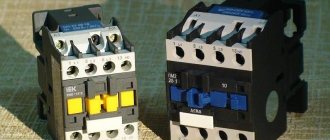
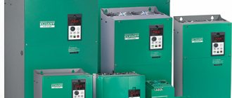
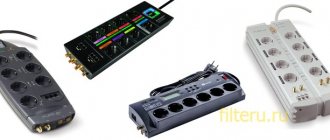
Appearance of frequency converters
Frequency converters are used in the following cases:
- if necessary, change the rotation speed of the electric motor;
- if it is necessary to maintain the value of a process parameter (for example, pressure) by changing the rotation speed of the electric motor;
- no 380V power supply. Frequency converters with 220V power supply are supplied with power up to 2.2 kW inclusive. The engine power is not lost in this case (If the engine has the ability to switch “ star-delta
” 380/220, then it can be turned on from a single-phase 220V network); - connection to an industrial network of motors with a “non-standard” supply voltage and frequency is required.
In addition to the main functions, the inverter provides
- the ability to turn on reverse without additional equipment;
- motor starting current limitation;
- motor current control;
- smooth acceleration and braking (time adjustable);
- additional engine protection;
- possibility of skipping resonant frequencies;
- stabilization of motor torque even with fluctuations in input voltage;
- possibility of stopping with deceleration;
- the ability to save energy with a partially loaded engine (even without a feedback sensor);
- work with built-in timer and counter;
- transition to “sleep mode” with the pump turned off in the absence of water consumption;
- Possibility of automatic restart when power is restored.
All listed parameters (functionality) are supported by ELHART frequency converters of the EMD-MINI and EMD-PUMP series.
Why do you need a frequency converter?
The use of gate valves and control valves in production is gradually becoming a thing of the past. The asynchronous motors that replaced them are distinguished by their high performance and power, but they are also not without characteristic disadvantages. For example, control over the speed of rotation of the rotor requires additional elements. Starting currents exceed the rated currents up to seven times. Such shock overload affects the service life of the unit.
The highly economical operation of pumps is based on constant adjustment of technical indicators such as temperature, pressure and water flow. Optimizing the operation of smoke exhausters and fans requires adjusting the temperature, air pressure and gas rarefaction. The economical use of machines is provided by adjusting the engine rotation speed. In the conveyor specificity of work, an important feature is productivity. Special frequency units are designed to solve such problems.
For companies and enterprises, private converters are necessary in terms of:
- saving energy resources;
- long service life of the mechanical and electrical parts of process equipment;
- reducing cash costs for planned repair and maintenance procedures;
- conducting operational management, fundamental control over technical parameters, etc.
The use of a frequency drive also increases the technical efficiency of production by freeing up some equipment.
Application of frequency converters in elevators
The construction of multi-storey buildings has experienced rapid growth in recent decades. It is not surprising that the need to equip constructed buildings with reliable and comfortable elevator equipment continues unabated. A well-thought-out, well-installed and properly adjusted elevator provides future residents of the building with safety, convenience and the ability to quickly move vertically between floors, as well as deliver the necessary goods.
Classification of elevators
The most common type of elevator systems are passenger elevators. Most residential and office buildings are equipped with them. As a rule, the speed of movement of such elevators lies in the range of 45-105 meters per minute, and the load capacity is 450-1350 kg, which approximately corresponds to from six to twenty passengers. Freight elevators are often built in retail, industrial, warehouse and medical premises, their speed movement is approximately the same as that of passenger ones, and the carrying capacity is slightly higher - from 600 to 2500 kg.
There are some other, special types of lifts used for vertical movement of specific loads. In particular, these are special lifts for transporting cars, which are often built in multi-level parking areas. Conveyors for bulk cargo are installed in mills, elevators and some factories. A special place is occupied by escalator systems in supermarkets, train stations, subways, and airports. Drive equipment similar to that used in elevators and escalators is also used in overhead gates and doors.
Elevator drive device
The most common type of elevator drive is traction. In this case, the elevator car is raised and lowered using cables wound or reeled from a special drum. The rotation of the drum, in turn, is carried out by an asynchronous motor. A plunger hydraulic elevator has higher performance qualities, but it is more difficult to install and maintain. The moving block is moved by means of a plunger driven by a hydraulic cylinder located in the pipe.
All types of elevator drives use asynchronous electric motors. The widespread use of this type of engine is due to a number of significant advantages. The main one is the ability to smoothly adjust the speed of the engine shaft and, accordingly, the speed of movement of the load, in the case of an elevator - a cabin with cargo or passengers. In addition to the smooth running of the elevator, this adjustment allows you to save energy by reducing the power consumption of the drive depending on the load by reducing the voltage. The overall service life of both the engine and many other drive units is significantly increased.
The physical basis for adjusting the rotation speed is the ability to change the frequency of the alternating voltage supplied to the motor windings. This task is directly assigned to one of the key components of any asynchronous drive with frequency control, a frequency converter.
Operating principle of frequency converters
A frequency converter is an electronic device for adjusting the frequency of the output voltage. The converter output frequency is set by applying a control voltage to one of the inputs. The other input is supplied with the base supply voltage from the normal mains. The frequency converter consists of two key blocks - a rectifier and an inverter. The rectifier converts the input alternating current from a conventional electrical network, which has a constant standard frequency, into direct current. Then the direct current is supplied to the inverter, where it is again converted into alternating current, but at the frequency that is required, and this frequency can be changed using the control voltage.
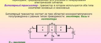
The inverter circuit is based on turn-off thyristors or bipolar transistors. Converters based on transistors are capable of operating in a wider range of currents and voltages, have high efficiency, and are resistant to continuous loads and pulsed effects.
Basic requirements for frequency converters
When choosing a brand of frequency converter to drive an elevator or lift, first of all, you should pay attention to several important characteristics. It is very important that the power of the converter matches the rated power of the electric motor used. The second significant parameter is the type of supply voltage. As a rule, drives and converters are used that are designed for a three-phase industrial network with a voltage of 380 V. But in some cases, single-phase power supply with a voltage of 220-240 V can be used. This type is in most cases designed for lower power.
A very important indicator for a frequency converter is the control range. Almost all converters operate reliably when the motor rotor speed is reduced to 10% of the nominal one. If an even lower rotation speed is required, not every converter will be suitable, and you need to clearly clarify this point with the supplier. Some converters have a recuperation mode - when the energy from system braking is converted and returned to the network. Such converters are somewhat more expensive, but often pay for themselves quite quickly during operation due to energy savings. The design of frequency converters provides protection of the entire drive from various emergency situations. The more protective functions included in a particular model, the more expensive it is, but these costs are often justified, since the system as a whole functions more reliably, safely and fails less often. As practice shows, when introducing frequency converters in elevators, the payback period for frequency converters is no more than 1.5 years. Mechanical maintenance costs are also significantly reduced. You can get more information by contacting our specialists in a convenient way for you in the Contacts section
Material prepared by chastotinik.com.ua
Where are frequency converters used?
The equipment is widely used in industrial applications and devices where it is necessary to change the motor rotation speed, measures to combat amplitude starting currents or adjustments in control parts (combinations of elementary converters using feedback), etc. Let's consider their use as needed:
Pumps. Since power consumption is proportional, as is known, to the cube of the rotation speed, the use of a frequency converter allows saving energy consumption by up to 60%, in comparison with the method of power regulation using dampers on the pipe. The annual use of the frequency converter pays for all the costs of its purchase. The devices also allow:
- reduce heat and water losses by 5 - 10%,
- reduce the number of pipeline accidents;
- provide complete protection of the electric motor.
An additional advantage is the solution to the problem with water hammer: working inverters smooth out the start/stop of the pump. At modernized pumping stations, systems have been installed that allow pumps to be controlled in a group manner without the need to install a controller.
Fans. Everything said above for pumps also applies to fans. As for the savings in electricity consumption, they are even more significant here, since in order to directly start large fans, more powerful motor units are often used. Improvement of technological installations leads to increased profitability of production. Efficiency is also achieved by reducing idle losses.
Transporters. Adaptation of the movement speed to the speed of the technological system, which is not a constant value. A smooth start significantly increases the service life of the mechanical part of the system, since shock loads damage technical equipment.
The scope of use of frequency converters is quite extensive. Among controllable pump-type inverters of small power, we can also distinguish centrifugal pumps, compressors, centrifuges, blowers, etc.
The general industrial series of medium-power VFD-controlled frequency generators includes motors in fans, smoke exhausters, water supply systems, mixers, dispensers, and production lines.
It is difficult to imagine elevator and other lifting and transport equipment with significant overloads during start/stop without vector control using converters.
The use of an inverter with feedback makes it possible to ensure the accuracy of the rotation speed, which will be the key to improving the quality of the technological process and solving assigned problems. Well-known manufacturers have a number of models focused on operating mode in a closed system. The equipment is recommended for use in the woodworking industry, robotics, precision positioning systems, etc.
All of the listed equipment can be controlled using converters with analog-to-digital inputs/outputs for regulation, remote control and monitoring via a serial communication line.
Are losses inevitable?
Let us dwell in more detail on the electrical losses that occur in an asynchronous electric motor.
The operation of an electric drive is characterized by a number of electrical and mechanical quantities.
Electrical quantities include:
- mains voltage,
- motor current,
- magnetic flux,
- electromotive force (EMF).
The main mechanical quantities are:
- rotation speed n (rpm),
- rotating torque M (N•m) of the engine,
- mechanical power of the electric motor P (W), determined by the product of torque and rotational speed: P=(M•n)/(9.55).
To denote the speed of rotational motion, along with the rotation frequency n, another quantity known from physics is used - the angular velocity ω, which is expressed in radians per second (rad/s).
There is the following relationship between the angular velocity ω and the rotation frequency n: when taken into account, the formula takes the form:
The dependence of the engine torque M on the rotational speed of its rotor n is called the mechanical characteristic of the electric motor. Note that when an asynchronous machine operates, the so-called electromagnetic power is transmitted from the stator to the rotor through the air gap using an electromagnetic field: Part of this power is transmitted to the rotor shaft in the form of mechanical power according to expression (2), and the rest is released in the form of losses in active resistances of all three phases of the rotor circuit.
These losses, called electrical, are equal to:
Thus, electrical losses are determined by the square of the current passing through the windings.
They are largely determined by the load of the asynchronous motor. All other types of losses, except electrical ones, change less significantly with load.
Therefore, let us consider how the electrical losses of an asynchronous motor change when the rotation speed is controlled.
Electrical losses directly in the rotor winding of an electric motor are released in the form of heat inside the machine and therefore determine its heating. Obviously, the greater the electrical losses in the rotor circuit, the lower the efficiency of the engine, the less economical its operation.
Considering that stator losses are approximately proportional to rotor losses, the desire to reduce electrical losses in the rotor is even more understandable. That method of regulating the engine speed is economical, in which the electrical losses in the rotor are relatively small.
From the analysis of the expressions it follows that the most economical way to control motors is at a rotor speed close to synchronous.
Other advantages of frequency drivers:
- smooth regulation of engine rotation speed makes it possible not to use gearboxes, variators, chokes and other control equipment, which makes the control structure simpler, cheaper and significantly more reliable;
- frequency drives combined with IM can be completely used to replace DC electric drives;
- it is possible to create multifunctional drive control systems based on an inverter with a controller;
- modernization of the technological structure can be carried out without interruption in work.
Advantages of using variable frequency drives for IM control
- Facilitates the starting mode of the drive.
- Allows the engine to run for a long time, regardless of the load level.
- Provides greater accuracy of adjustment operations.
- Allows you to monitor the status of individual nodes in the circuits of an industrial electrical network. Due to this, it is possible to keep a constant record of the amount of time the engines have worked in order to later evaluate their performance.
- The presence of electronic components makes it possible to diagnose engine malfunctions remotely.
- Various feedback sensors (pressure, temperature) can be connected to the device. As a result, the rotation speed will be stable under constantly changing loads.
- When the mains voltage fails, controlled braking and restart are activated.
- As a result:
- the level of efficiency increases due to which you can save about 30-35% of electricity;
- the quantity and quality of the final product increases;
- wear of component mechanisms is reduced;
- equipment service life increases.
Operating principle
If we explain the principle of operation of a frequency converter, then we can say that the use of this device allows you to effectively and efficiently control the operation of powerful asynchronous electric motors.
The equipment is a variable frequency drive (VFD), due to which the technical characteristics of machines and mechanisms have been improved. To change the speed of the motor shaft, it is necessary to adjust the amplitude of the voltage and frequency. The operating principle of the frequency converter is based on two methods:
- Scalar control - allows adjustment according to a linear law, when the amplitude and frequency depend proportionally on each other. That is, a change in frequency affects the amplitude of the incoming voltage, which affects the torque and power factor of the mechanism. It is very important that the load torque on the motor shaft remains the same, and the ratio of voltage to output frequency remains unchanged.
- Vector regulation - allows you to maintain a constant load at any frequency changes. Provides more precise control and the electric drive responds more smoothly to changes in output power. It should be taken into account that the rotation torque is affected by the magnitude of the stator current, or more precisely, by the magnetic field that it creates.
This will be interesting to you Features of calculating capacitance
Industrial voltage is supplied to a rectifier, which smoothes out the sinusoids, leaving a ripple in the signal. To eliminate them and smooth out the shape of the output voltage, capacitors with inductance are provided in the design.
From the rectifier, the signal is supplied to the input of an inverter, consisting of six transistors with diodes that perform protective functions against reverse polarity voltage. Sometimes thyristors can be used in circuits, but they operate more slowly and with more noise.
To ensure smooth braking of rotation, an adjustable transistor with powerful resistance is built into the design. A frequency converter for an electric motor works on this principle.