The power and electric current of the frequency converter, the voltage when two motors are connected to it at the same time, is selected in excess of 20% of the total power of the electric motors. To calculate the length of the electrical cable, you need to add up the dimensions of all the cables of the two motors. It is necessary to reduce the overall length if you connect two electric motors specifically to the contacts of the frequency converter. With two electric motors, it is advisable to install a motor choke, despite the fact that the total length of these cables is not more than the longest length.
Many frequency converters do not tolerate connecting and disconnecting current electric motors with contactors with an electric drive during operation, but only by turning on the STOP command on the drive.
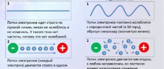
Why do you need a frequency converter?
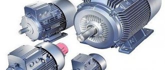
The inverter is the most advanced electronic device through which you can spin an asynchronous motor. Here are the main functions of the frequency converter:
- Engine start/stop,
- Smooth acceleration/deceleration (braking),
- Changing the operating speed from 0 to 100% and above the nominal,
- Motor protection (there are several of them - by current, temperature, etc.),
- Reverse,
- Several control options (discrete, analog, according to the program - from buttons, relays, potentiometers, sensors, controller, etc.).
The frequency converter has several names that are used on equal terms:
- frequency converter (FC) is the official name, it is used by most manufacturers in their documentation,
- frequency converter (FC),
- chastotnik – can be considered jargon, but is used most often in conversation,
- inverter,
- Inverter, Frequency Converter (FC), Variable Frequency Drive (VFD) - in English.
All these names can be used in other areas, so sometimes you need to clarify. Regarding the topic of the article, our area is connecting a frequency converter for three-phase asynchronous motors.
Of course, an asynchronous motor can be driven not only through an inverter; there are several different devices for this. I have a lot of articles on connecting engines, here are the main ones:
- Connection diagrams for a three-phase electric motor
- Magnetic starter connection diagrams
- Connecting a two-speed asynchronous motor
- Motor connection diagrams “Star” and “Triangle”
- Relay for star-delta motor control
- Soft starter (soft starter) - device and application
- Soft start device (SCD) of the electric motor. Application example
- Description of the operation of circuits on relays and contactors
Types of frequency converters
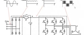
Modern frequency converters are distinguished by a variety of circuits, which can be grouped into several categories:
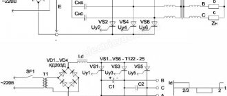
- High-voltage two-transformer
The operating principle of such a device is to sequentially convert voltage using a step-down and step-up transformer, convert frequency using a low-voltage converter, and smooth out peak overvoltages at the output using a sine wave filter. The operation scheme is as follows: a supply voltage of 6000 V is supplied to a step-down transformer and 400 (660) V is obtained at its output, then it is supplied to a low-voltage converter and, after changing the frequency, it is supplied to a step-up transformer to increase the voltage value to the initial one.
- Thyristor converters
Such devices consist of multi-level frequency converters based on thyristors. Structurally, they consist of a transformer (providing a decrease in the supply voltage), diodes (for rectification) and capacitors (for smoothing). Multipulse circuits are also used to reduce the level of higher harmonics.
Thyristor converters have a high efficiency of up to 98% and a large output frequency range of 0-300 Hz, which is a positive and sought-after characteristic for modern equipment.
- Transistor frequency converters
Such frequency converters are high-tech devices that are assembled using transistors of various types. Structurally, they have transistor inverter cells and a multi-winding dry transformer of a special design. Such a converter is controlled using a microprocessor, which allows you to fine-tune the operation of the equipment and control the entire process of operation of various engines. Transistor frequency converters, just like thyristor ones, have high efficiency and a wide frequency control range.
Connection diagram and operation of the frequency converter
The inverter switching circuit, very simply, looks like this:
The simplest circuit for switching on a frequency converter
What is this elementary circuit for? - you ask. However, there are electronic engineers who will not be able to draw it.
It can be even simpler if you remove external controls. After all, you can control the inverter directly from the front panel.
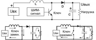
The operation of the frequency converter, if we talk about the above diagram, is described simply: Three phases at the input, three phases at the output. At the input, three phases usually have a linear voltage of 380 V with a frequency of 50 Hz. Depending on the type of connected motor, the linear voltage at the output varies from 0 to 380 V, while the output frequency depends on the voltage and can vary from 0 to 100 Hz or more (mechanics can no longer withstand this). How frequency depends on voltage is described by the voltage-frequency characteristic, which in the simplest case will be linear:
How does a frequency converter work? Typical linear voltage versus frequency
This graph is key to understanding the operating principle of the frequency converter and its settings. Please note that the voltage-frequency characteristic shows the names of the main points and parameter numbers.
Of course, there are a lot of nuances in such matters, but I won’t go into details. If you need a lot of theory and operating principles of the inverter, at the end of the article there will be something to download and read. Including my review article in the magazine.
This introduction can be completed. Next will be an example of connecting an inverter, where I will show in practice what parameters I configure and why.
Option 1
Hello everybody. So I decided to write an article about the asynchronous drive and frequency converter that I made. My friend had to turn the sawmill, and turn it well. And I myself was involved in pulse electronics and immediately offered him a frequency generator. Yes, it was possible to buy a proprietary converter, and I had to deal with them, parameterize them, but I wanted my own, HOMEMADE! And the circular drive is not critical to the quality of speed control, but it must be prepared for shock loads and operation under overload. Also, the control is as simple as possible using a couple of buttons and no parameters there.
The main advantages of a variable frequency drive (maybe I’ll repeat it for some):
We form from one phase 220 V full-fledged 3 phases 220 V with a shift of 120 degrees, and we have full torque and power on the shaft.
Increased starting torque and smooth start without high starting current
There is no magnetization and unnecessary heating of the motor, as when using capacitors.
Ability to easily adjust speed and direction if necessary.
Here's the diagram that came together:
A 3-phase bridge on IGBT transistors with freewheeling diodes (I used the existing G4PH50UD) is controlled through an HCPL 3120 optodriver (bootstrap power supply circuit) by a PIC16F628A microcontroller. At the input there is a quenching capacitor for smooth charging of the DC link electrolytes. Then it is shunted by a relay and the logical readiness level simultaneously arrives at the microcontroller. There is also a short-circuit current protection trigger. and severe engine overload. Control is carried out by 2 buttons and a toggle switch for changing the direction of rotation.
I assembled the power part using a hinged installation. The controller board looks like this:
I soldered 270 k parallel resistors on the pass-through gate capacitors (I forgot to draw places for them) on the back of the board, then I wanted to replace them with SMD ones, but I left them that way.
This is what this board looks like after soldering:
View from the other side
To power the control, a standard switching flyback (FLAYBACK) power supply was assembled.
His diagram:
You can use any 24V power supply, but one that is stabilized and delays the loss of output voltage from the moment the mains power goes out by a couple of seconds. This is necessary so that the drive has time to switch off due to a DC error. I achieved by installing electrolyte C1 with a larger capacity.
Now about the most important thing... about the microcontroller program. Programming simple blinkers was not difficult for me, but here I had to stretch my brain. Having searched the Internet, I did not find any suitable information at that time. I was also offered to supply specialized controllers, for example a MOTOROLA MC3PHAC controller. But, I repeat, I wanted my own. I began to understand in detail PWM modulation, how and when to open which transistor... Certain patterns emerged and a template emerged for the simplest program for working out delays, with the help of which you can produce a satisfactory sinus PWM and regulate the voltage. Of course, the controller didn’t have time to count anything, the interrupts didn’t give me what I needed, and so I immediately discarded the idea of a cool PWM calculation on the PIC16F628A. The result was a matrix of constants, which was processed by the controller. They set both frequency and voltage. To be honest, I spent a long time fiddling around. The sawmill was already using capacitors at full speed when the first version of the firmware came out. I tested the entire circuit first on a 180-watt fan motor. This is what the “experimental setup” looked like:
The first experiments showed that this project definitely has a future.
The program was refined and, as a result, after the promotion of the 4 kW engine, it could be assembled and go to the sawmill.
The comrade was pleasantly surprised, although he was skeptical from the very beginning. I was also surprised, because... short circuit protection was checked. (accidentally happened in boron engine). Everything remained alive. The 1.5 kW 1440 rpm engine easily chewed timber with a 300 mm disc. The pulleys are one to one. When there were impacts and knots, the light dimmed slightly, but the engine did not stop. I also had to tighten the belt a lot, because... slid under heavy load. Then they put it in double gear.
Now I’m still finalizing the program, it will become even better, the operating algorithm of the shim is a little more complicated, there are more modes, the ability to spin up above the nominal value... and here below is the simplest version that has been working on the saw for about a year.
Its characteristics:
- Output Frequency: 2.5-50Hz, 1.25Hz step; The PWM frequency is synchronous and variable. Range approximately 1700-3300 Hz; Scalar control mode U/F, motor power up to 4 kW.
- The minimum operating frequency after pressing the RUN button once is 10Hz.
- When you hold down the RUN button, acceleration occurs; when you release it, the frequency remains the one to which you managed to accelerate. Maximum 50 Hz - signalized by LED. Acceleration time is about 2 s.
- The “ready” LED signals that the drive is ready to start.
- The reverse is polled in the ready state.
- There are no braking or frequency control modes, but they are not needed in this case.
- When Stop or RESET is pressed, a coasting stop occurs.
Program and signet at the end of the material.
Option 2
In this article we will talk about a frequency converter, or in common parlance, a frequency converter. This frequency generator, and later a frequency drive, is capable of controlling a 3-phase asynchronous motor. In this frequency drive (FC), I use an intelligent power module from International Rectifier, specifically IRAMS10UP60B (on AliExpress), the only thing I did with it was bend the legs, so, in fact, the module turned out to be IRAMS10UP60B-2 . The choice for this module fell mainly because of the built-in driver. The main feature of the built-in driver is the ability to use 3 PWM instead of 6 PWM channels. In addition, the price for this module on eBay is about 270 rubles. I use ATmega48 as a control controller.
When developing this drive, I focused on design efficiency, minimal cost, the presence of the necessary protection, and design flexibility. The result is a frequency drive with the following characteristics (functions):
- Output frequency 5-200 Hz
- Frequency set speed 5-50 Hz per second
- Frequency reduction rate 5-50 Hz per second
- 4 fixed speed (each from 5-200 Hz)
- Volt addition 0-20%
- Two “factory” settings that can always be activated
- Motor magnetization function
- Full engine stop function
- Input for reverse (as without it)
- Possibility to change U/F characteristic
- Ability to set frequency using a variable resistor
- IGBT module temperature monitoring (alarm in case of overheating and drive stop)
- DC link voltage monitoring (DC link over/under voltage, alarm and drive stop)
- DC link pre charge
- The maximum power with this module is 750 W, but it turns 1.1 kW on my CNC
- All this on one board measuring 8 x 13 cm.
At the moment, protection against overcurrent or short circuit is not implemented (I think there is no point, although I left a free leg in the MK with an interruption by change)
Actually, the diagram of this device:
Project in layout
Below is a photo of what I got
Printed circuit board of this device (available in lay for iron)
This photo shows a fully working copy, tested and run-in (it does not have a socket located on the left). The second one is for testing the atmega 48 before shipping (located on the right).
This photo shows the same irams (I made it with extra space, it should fit iramx16up60b)
Device operation algorithm
Initially, the MK (microcontroller) is configured to work with an electric motor with a rated voltage of 220 V at a rotating field frequency of 50 Hz (i.e. a regular asynchronous machine, on which 220 V 50 Hz is written). The frequency increase speed is set at 15 Hz/sec (i.e., acceleration to 50 Hz will take a little more than 3 seconds, to 150 Hz - 10 seconds). Volt additive is set at 10%, magnetization duration is 1 second. (constant value remains unchanged), duration of DC braking is 1 sec. (a constant value is unchanged). It should be noted that the voltage during magnetization, as well as during braking, is an additive voltage and changes simultaneously. By the way, the frequency converter is scalar, i.e. As the output frequency increases, the output voltage increases.
After power is applied, the DC link capacitance is charged. As soon as the voltage reaches 220V (constant), with a certain delay, the precharge relay turns on and my only LED L1 lights up. From this point on, the drive is ready to start. There are 6 inputs to control the frequency converter:
- On (if only this input is provided, the VSD will rotate the motor at a frequency of 5 Hz)
- On+reverse (if you apply only this input, the state of emergency will rotate the motor at a frequency of 5 Hz, but in the other direction)
- 1 fixed frequency (set by R1)
- 2 fixed frequency (set by R2)
- 3 fixed frequency (set by R3)
- 4 fixed frequency (set by R4)
There is one But in this management. If you change the task on the resistor while the engine is rotating, it will change only after the command is given again (on) or (on + reverse). In other words, data from resistors is read while these two signals are missing. If you plan to regulate the speed using a resistor during operation, then you need to install jumper J1. In this mode, only the first resistor is active, and resistor R4 limits the maximum frequency, that is, if it is set to 50% (2.5 volts 4 “pin.” in the photo below 5 ground), then the frequency of R1 will be regulated by a resistor from 5 to 100 Hz.
To set the rotation frequency, you need to take into account that 5v at the input to the MK corresponds to 200 Hz, 1v-40 Hz, 1.25v-50 Hz, etc. To measure voltage, contacts 1-5 are provided, where 1-4 correspond to resistor numbers, 5 is a common minus (pictured below). Resistor R5 is used to adjust the voltage scaling of DC link 1 to -100 V (in the diagram R30).
Arrangement of elements
Attention! The board is under life-threatening voltage. The control inputs are isolated by optocouplers.
Settings Features
Setting up the drive before turning it on for the first time comes down to checking the installation of electronic components and setting the voltage divider for the DC link (R2).
100 Volts of the DC link should correspond to 1 volt at 23 (MK leg) - this is IMPORTANT!!!!….The setup is complete…
Before applying mains voltage, it is necessary to wash the board (remove any remaining rosin) from the soldering side with solvent or alcohol, preferably varnish it.
The drive has "factory" settings for the motor (220 V 50 Hz):
- Enable drive
- Wait for readiness (if power is supplied only to the MK, just wait 2-3 seconds)
- Press and hold button B1 until LED L1 starts flashing, release button B1
- Give the 1st speed selection command. As soon as the LED stops blinking, remove the command
- The drive is configured. Depending on whether ………………….the LED was on (if it was not on, the drive expects voltage on the DC link).
With this setting, the following parameters are automatically recorded:
- Rated motor frequency at 220 V - 50 Hz
- Volt addition (magnetizing voltage, braking voltage) - 10%
- Acceleration rate 15 Hz/sec
- Braking intensity 15 Hz/sec
If you send a signal to select the second speed, the following parameters will be written to the EEPROM (the only difference is the frequency):
- Rated motor frequency at 220 V - 30 Hz
- Volt addition (magnetizing voltage, braking voltage) 10%
- Acceleration rate 15 Hz/sec
- Braking intensity 15 Hz/sec
Finally, the third Settings option:
- Press button B1 and hold
- Wait until the LED starts flashing
- Release button B1
- Do not apply voltage to the 1st or 2nd speed selection inputs
- Set parameters using trimming resistors
- Press and hold button B1 until the LED starts blinking
Thus, as long as the LED is flashing, the drive is in setting mode. In this mode, when the 1st or 2nd speed input is applied, parameters are written to the EEPROM. If you do not apply voltage to the 1st or 2nd speed selection inputs, then the fixed parameters will not be written to the EEPROM, but will be set by trimming resistors.
- The resistor sets the rated frequency of the motor at 220 V (So, for example, if the motor says 200 Hz / 220, then the resistor needs to be unscrewed to the maximum; if it says 100 Hz / 220 V, you need to achieve 2.5 Volts on the 1st contact. (1 Volt on the first contact corresponds to 40 Hz); if the motor says 50 Hz/400 V, then you need to set 27 Hz/0.68 V (for example: (50/400)*220=27 Hz) since we need to know the frequency of the motor at 220V supply motor. The range of parameter changes is 25 Hz - 200 Hz. (1 Volt on pin 1 corresponds to 40 Hz)
- The resistor is responsible for the volt addition. 1 Volt on the 2nd contact corresponds to 4% of the additive voltage (my opinion is to choose at the level of 10%, that is, increase 2.5 volts with caution) Setting range 0-20% of the mains voltage (1 Volt on the 2nd contact corresponds to 4%)
- The acceleration intensity of 1 V corresponds to 10 Hz/sec (in my opinion, 15 -25 Hz/sec is optimal). The setting range is 5 Hz/sec - 50 Hz/sec. (1 volt on pin 3 corresponds to 10 Hz/sec)
- The braking intensity of 1 V corresponds to 10 Hz/sec (in my opinion, 10 -15 Hz/sec is optimal) Setting range 5 Hz/sec - 50 Hz/sec. (1 volt on pin 4 corresponds to 10 Hz/sec)
After all resistors are set, press and hold button B1 until the LED stops blinking!!!! If the LED blinked and lit up, then the drive is ready to start. If the LED blinked and did NOT light up, then wait 5 seconds, and only then turn off the power from the controller.
Below is the volt-frequency characteristic of the device for a 220 V 50 Hz motor with a volt addition of 10%.
- Umax is the maximum voltage that the converter is capable of producing
- Uv.d. - additive volt voltage as a percentage of the network voltage
- Fn.d. - rated engine speed at 220 V. IMPORTANT
- Fmax is the maximum output frequency of the converter.
Another setup example
Let's assume you have a motor with a rated frequency of 50 Hz and a rated voltage of 80 V. To find out what the rated frequency will be at 220 V you need to: divide 220 V by the rated voltage and multiply by the rated frequency (220/80*50=137 Hz). Thus, we get that the voltage on 1 contact (resistor) needs to be set to 137/40 = 3.45 V.
Simulation in Proteus overclocking 0-50 Hz of one phase (the computer freezes on 3 phases)
As can be seen from the screenshot, the amplitude of the sine increases with increasing frequency. Acceleration takes approximately 3.1 seconds.
Regarding nutrition
I recommend using a transformer, as it is the most reliable option. My test boards do not have diode bridges and a stabilizer for the igbt module 7812. Two printed circuit boards are available for download. The first one is the one presented in the review. The second has minor changes, a diode bridge and a stabilizer have been added. The protective diode must be installed P6KE18A or 1.5KE18A.
An example of transformer placement, as it turned out, is not at all difficult to find.
Which motor can be connected to this frequency converter?
It all depends on the module. In principle, you can connect any one, the main thing is that its resistance for the irams10up60 module is more than 9 Ohms. It should be taken into account that the irams10up60 module is designed for a small pulse current and has built-in protection at the level of 15 A. This is very little. But for motors 50 Hz 220 V 750 W, this is beyond the eyes. If you have a high-speed spindle, then most likely it has low winding resistance. This module can generate a pulse current. When using the IRAMX16UP60B module (the legs will have to be bent yourself), the engine power according to the datasheet increases from 0.75 to 2.2 kW.
The main thing for this module is: the short circuit current is 140 A versus 47 A, the protection is set at 25 A. It’s up to you to decide which module to use. It must be remembered that 1 kW requires 1000 uF of dc link capacitance.
Regarding short circuit protection. If you do not install a smoothing choke at the drive immediately after the output (limiting the rate of current rise) and short-circuit the output of the module, then the module will suffer. If you have an iramX module, there are chances. But with IRAMS there is zero chance, verified.
The program occupies 4096 KB of memory out of 4098. Everything is compressed and optimized for the maximum size of the program. The cycle time is a fixed value equal to 10 ms.
At the moment, everything described above works and has been tested.
If you use 20 MHz quartz, the drive will be 10-400 Hz; acceleration rate 10-100 Hz/sec; The PWM frequency will increase to 10 kHz; The cycle time will drop to 5ms.
Looking ahead, the next frequency converter will be implemented on ATmega64, have a PWM width of not 8, but 10 Bits, have a display and many parameters.
Below, watch the video of setting up the drive, checking overheat protection, demonstrating operation (I use a 380 V 50 Hz motor, and the settings for 220 V 50 Hz). I did this on purpose to check how PWM works with a minimum task.)
Why was the inverter needed?
An old acquaintance from the shoe industry contacted me. For the pre-sale preparation of women's boots, he requires a polishing operation to make the boots shine.
By the way, I already made a hot stamping press with him, where I installed a FiF temperature regulator. Now you can get beautiful images on boots.
The polishing machine was in a disgusting state, but they managed to bring it back to life by rebuilding the Soviet contactors and connecting the motors.
However, for high quality leather surface finishing, it was preferable that the linear polishing speed could be varied. It is impossible to do this in any other way other than the IF. Replacing the pulleys was not considered - the speed must be changed quickly and without tools.
As a result, I installed a Delta frequency converter. I connected and configured it so that you can change the speed of the engine connected through it by pressing buttons on the control panel. Next are the details.
Machine structure, before installing the inverter
So here's what we had initially:
Leather polishing machine
The machine has two motors – dust extraction and polishing drive.
Shoe leather polishing machine side view
Electrical internals of a shoe polishing machine
On the left in the photo are the introductory circuit breaker and contactors. This is the entire diagram of the machine.
Old polishing scheme. Contactors for extraction and polishing motors
There are also three control buttons – Start hood, Start polishing, Stop:
Old contactor control buttons. On the left axis there is felt (felt) for polishing
The hood does not concern us, although I will install buttons to turn it on. And we will connect the polishing motor via the inverter.
An electric motor that is connected via a frequency converter
Asynchronous motor in operation. Pulley and belt drive
Nameplate of an asynchronous motor, which is to be connected via a frequency converter
When connecting the inverter, it is very important to know the motor parameters. The catch was that the information on the nameplate was not readable. After all, a single drive is being configured, and this is a combination of inverter + motor.
Looking ahead, I will say that by the appearance of the engine I determined that it was a 3000 rpm engine, and by measuring the current and testing I realized that the engine power was 1 kW.
I remembered that I have another article on engines - what is the starting current of an engine, and how to find it out.
Alternate connection of electric motors
When using a non-specialized frequency converter to alternately control several drives, you must:
- Provide a switching lock when the electric motor is running. All switching must be done when the frequency generator is switched to the “Stop” mode.
- Implement a protective shutdown of the inverter before disconnecting contactors or switches in the event of a voltage loss in the output circuit.
Danfoss produces several series of special frequency converters for controlling several electric motors. All functions necessary for this are implemented in the software and hardware of the inverter. The operation of each drive can be programmed in the settings. The inverter has built-in thermal relays and corresponding inputs and outputs.
The use of such devices eliminates the need for phasing motors, calculating the characteristics of the frequency converter, the need to install additional switching and protective devices, and also guarantees correct operation of the drives in all intended modes.
Installation and connection of the frequency converter
Now I’ll tell you and show you step by step how I installed the frequency switch.
First, I prepared the front panel.
Frequency control panel, buttons, voltmeter
The panel was made from textolite. The panel will have buttons with NO and NC contacts (without fixation), and a voltmeter as a tachometer.
The panel is on the reverse side - the buttons are fixed, all that remains is to install the contacts and secure the voltmeter
To put it simply, the whole rework consisted in the fact that I threw out the contactor and installed a Delta frequency converter of 1.5 kW:
Delta frequency drive with a power of 1.5 kW instead of a contactor
To be honest, 1.5 kW is a bit much, that is, I chose the inverter with a large margin (almost 2 times). It was not possible to find less power. All the better from an electrical point of view - the reserve does not stretch the pocket.
Photo of frequency converter installation:
The frequency generator is installed in the machine on the side door, instead of a contactor
I know that the installation is not perfect, it would be nice to use lugs and bands on the wires, but let's not talk about that...
Delta inverter, the polishing motor is connected through it
Zero in the power supply of the machine and the frequency generator is not used, only 3 phases and ground (PEN conductor) are supplied.
Inverter power supply – 3 phases and ground to input terminals R, S, T
Don’t take my example - from the switchgear the protective conductor must go to the PE bus, and from each individual terminal - separately to the inverter terminal, to the housing, and wherever else necessary.
Delta drive connection. Control terminals and output power terminals for motor U, V, W
Is it possible to have two identical motors for one frequency drive?
Theoretically, such a connection is not recommended, especially for a vector frequency converter. It can be connected to a scalar motor if the electric motors operate together on the same shaft, and they can be phased smoothly through a slip current clutch. It is possible to adjust the arrangement of the rotors between each other using a coupling. Then the coupling must be secured. At a small load, adjust the currents between the motors using current clamps.
There are certain current and voltage converters that allow the operation of two electric motors simultaneously under a joint load. Although, both motors have their own frequency generator and an additional control line between the converters.
It is problematic to connect two equal electric motors. You can connect one by one without problems, even with different parameters. The connection is made through package-type starters and switches.
Micromaster can control two electric motors at once. The parameter values must be created correctly, and heat protection must be set separately.
You can install two motors on one frequency converter, but on two different shafts. In the frequency generator, extend one contact at a time from the corresponding electric motor.
Let's give an example. We have two 0.5 kW motors. We want them to be operated together at one load of 0.8 kW per frequency converter. It is impractical to purchase two converters at once; they operate synchronously, and it is inconvenient to adjust two frequency converters.
Connecting both electric motors with one frequency converter at once entails some nuances. The main difficulty is the protection of the engines. It is difficult to find a fault problem with one of the motors when connected in parallel. For example, two factory motors operate on one converter. Three cutters were working. One cutter failed and became dull. Because of this, the frequency converter began to heat up. It is necessary to install thermal relays with converter protection for maximum current and voltage on all motors. Otherwise, the current frequency protection relay cannot recognize the fault. It is bad if there is a switch at the output of the converter. If the motor breaks during operation, the frequency converter will fail.
Thermal protection is of great importance, but it is possible to do without it. It is allowed to be on a vector without feedback; a complete vector is difficult to obtain. Through experimentation, possibilities will emerge. On a working converter at the output, everything functions without difficulties. If you do not overload frequency converters with capacitors, they will last a long time.
Hyundai converters are well suited for two electric motors. They have their own protection against heating (thermal relays), which is necessary for each motor. This is determined by several facts:
- The load is unevenly distributed. Electric current of different magnitude on both motors.
- Possibility of switching off one motor. The protection for the 0.8 kW motor, built into the frequency converter, will not work.
It is recommended to place an equal load on the frequency generator from both engines. This refers to the load during operation. A break during no-load operation is normally tolerated by the current converter. When the supply voltage was suddenly cut off, the starting switch, which switches the electric motor, turned off more often than the frequency switch turned off.
What happened
As a result, the control panel looked like this:
Installed frequency converter in operation, control panel
I made stickers for the buttons using the Splan program and self-adhesive tape according to the method described in the article My Evolution of Labeling.
It will be clearer how everything works if I provide an electrical diagram.
Connecting 2 identical electric motors
The frequency converter is switched to scalar control mode. When operating on a general load, the electric motor shafts are connected with a sliding coupling. The currents of the motor windings must be equal. For protection, it is recommended to install thermal relays that are connected to the discrete input of the frequency converter. Danfoss also produces frequency converters with built-in protection devices. It is prohibited to include switching electrical devices in the “electric motor – frequency converter” circuit.
Frequency converter connection diagram
After the modification, the entire circuit of the machine, containing two drives, looks like this:
Frequency converter connection diagram
First of all, I will say that if you do everything wisely, then you need to provide protection at the input - install high-speed fuses or, at worst, circuit breakers with characteristic “B”. But what is, that is - the only defense is the Soviet 3p S6.
The extraction and polishing drives have two common parts - power and the “Stop” button. The “Stop” button (SB3) has two electrically independent contacts that stop both drives at once.
Particularly picky readers will definitely reproach me for my words that “zero is not used in the machine’s power supply.” But I have a ready answer)))
The hood drive is connected according to the classic self-retaining scheme, which I have written about more than once. Links are at the beginning of the article.
Let's take a closer look at what interests us - the inverter connection diagram:
Working diagram of Delta inverter connection
As for the power part, I already said, everything is simple there.
In terms of management. The names of the terminals are indicated on the diagram; they can also be seen in the installation photo. In order for the whole circuit to work correctly, all these terminals need to be programmed correctly, without this there is nowhere to connect the inverter. Therefore, setting up the inverter and connecting it are two inextricably linked concepts.
On setting up and connecting the inverter
Schemes of dynamic braking of an asynchronous motor with direct current
Figure 1 - Diagram of dynamic braking of an asynchronous motor
Organizing a forced stop of an asynchronous motor using the electrical principle can be carried out in several ways:
- Electrodynamic. This is a classic option, in which two phases need to be short-circuited and transferred to DC power,
- Regenerative (generator). Characterized by the return of excess electricity to the network,
- Anti-inclusion. This option is implemented using a reverse circuit, that is, with the phases connected through a pair of magnetic starters,
- Self-excitation. By connecting a battery of capacitors to the stator windings.
Expert opinion
It-Technology, Electrical power and electronics specialist
Ask questions to the “Specialist for modernization of energy generation systems”
Advantages of an asynchronous motor compared to a DC motor It is obvious that the operating modes of asynchronous electric motors directly depend on their design and general operating principles. Ask, I'm in touch!
Speed indication
Was that even possible?
A cool feature of many inverters is the discrete and analog output terminals. Many events can be programmed onto them. For example, in an article about installing an inverter in a band saw (pipe cutter), I said that the output relay closes when the target frequency is reached and gives a signal to the next function.
Here I used the analog output to indicate engine speed. For this purpose, the analogue output function “Output frequency indication” is set (parameter 03.03 = 0). In this case, the maximum frequency of 60 Hz corresponds to a voltage of 10 V. I slightly adjusted the voltmeter readings (by 3%) in parameter 03.04.
| Inverter speed table | ||
| Voltmeter readings | Exit Frequency | Engine speed |
| 3,4 | 20 | 1200 |
| 5,1 | 30 | 1800 |
| 6,8 | 40 | 2400 |
| 8,4 | 50 | 3000 |
| 9,3 | 55 | 3300 |
| 10 | 60 | 3600 |
The output analog voltage is fed to a DC voltmeter with a limit of 30 V. As a result, the machine operator observes a number on the indicator that uniquely corresponds to the polishing speed.