The name intermediate relays did not arise from the fundamental difference between the operating mechanism of the device and other relays, but rather from the functional purpose of this type. Switching of mechanical contacts is carried out by an electromagnet, in semiconductor models through pnp junctions. The main purpose of intermediate elements is to control the switching of circuits with high voltage and current, power systems or individual installations, and electric motors of machine tools. A distinctive feature of intermediate relays can be considered the presence of several groups with a large number of contacts. This design allows you to control an entire switching network with one operation.
Purpose and scope of intermediate relays
It is difficult to list the industries in which intermediate relays are used. In all industries, devices for household use, especially in elements of systems with electronic and electrical equipment, an intermediate relay can be installed.
There are several cases where auxiliary relays are used in complex electrical systems:
- For switching sections in various networks independent from each other;
- To increase the response delay of protective elements in circuits with high load currents;
- In secondary circuits, to control the parameters and operating modes of individual elements in high voltage circuits;
One relay on a production line can perform several switching operations simultaneously or sequentially in power or control circuits. In heating and water supply systems, when the deep-well pump is turned on, power is supplied to the relay coil, and when the group of contacts is closed, the control system for the operation of the pump is turned on. The operator’s display displays the main parameters: the presence of voltage on the pump, load currents in each phase, temperature and others, depending on the complexity of the circuit, as necessary.
The other pair will simultaneously close the power supply contacts to the coil of the magnetic starter, when triggered, the current will flow to all three phases of the pump motor. If the starter is assembled using a reversible circuit, another group simultaneously turns off the reversible circuit, eliminating a short circuit.
In a heating system, a signal with weak currents is not capable of turning on the coils of powerful magnetic starters or relays. Therefore, the intermediate relay acts as an amplifier of the control signal; the signal from the heat sensor turns on the intermediate relay, the contacts of which supply voltage to the windings of the magnetic starter, the contacts of which close and power is supplied to heating elements, boilers or other powerful heating devices.
Relay contacts.
Depending on the design features, the intermediate relay contacts are normally open
(closing),
normally closed
(breaking) or
changeover
.
3.1. Normally open contacts.
As long as the supply voltage is not applied to the relay coil, its normally open contacts are always open
.
When voltage is applied, the relay is activated and its contacts close
, completing the electrical circuit. The pictures below show the operation of a normally open contact.
3.2. Normally closed contacts.
Normally closed contacts work the other way around: as long as the relay is de-energized, they are always closed
.
When voltage is applied, the relay is activated and its contacts open
, breaking the electrical circuit. The pictures show the operation of a normally open contact.
3.3. Changeover contacts.
For changeover contacts with a de-energized coil, the average
the contact attached to the anchor is
common
and closed with one of the fixed contacts. When the relay is triggered, the middle contact, together with the armature, moves towards the other fixed contact and closes with it, while simultaneously breaking the connection with the first fixed contact. The pictures below show the operation of a changeover contact.
Many relays have not one, but several contact groups, which makes it possible to control several electrical circuits simultaneously.
There are special requirements for intermediate relay contacts. They must have low contact resistance, high wear resistance, low tendency to weld, high electrical conductivity and long service life.
During operation, the contacts with their current-carrying surfaces are pressed against each other with a certain force created by the return spring. The current-carrying surface of a contact in contact with the current-carrying surface of another contact is called the contact surface
, and the place where the current passes from one contact surface to another is called
electrical contact
.
The contact of two surfaces does not occur over the entire apparent area, but only in separate areas, since even with the most careful treatment of the contact surface, microscopic tubercles and roughness will still remain on it. Therefore, the total contact area
will depend on the material, the quality of the contact surfaces and the compression force. The figure shows the contact surfaces of the upper and lower contacts in a greatly enlarged view.
At the point where current passes from one contact to another, electrical resistance occurs, which is called contact resistance
. The magnitude of the contact resistance is significantly influenced by the magnitude of the contact pressure, as well as the resistance of the oxide and sulfide films covering the contacts, since they are poor conductors.
During long-term operation, the contact surfaces wear out and can become covered with soot deposits, oxide films, dust, and non-conducting particles. Contact wear can also be caused by mechanical, chemical and electrical factors.
Mechanical wear occurs when contact surfaces slide and impact. However, the main cause of contact destruction is electrical discharges
, arising when opening and closing circuits, especially DC circuits with an inductive load. At the moment of opening and closing, the phenomena of melting, evaporation and softening of the contact material, as well as the transfer of metal from one contact to another, occur on the contact surfaces.
Silver, alloys of hard and refractory metals (tungsten, rhenium, molybdenum) and metal-ceramic compositions are used as materials for relay contacts. The most widely used material is silver, which has low contact resistance, high electrical conductivity, good technological properties and relatively low cost.
It should be remembered that there are no absolutely reliable contacts, therefore, to increase their reliability, parallel and serial connection of contacts is used: when connected in series, the contacts can break a large current, and parallel connection increases the reliability of the electrical circuit.
Design and principle of operation of the intermediate relay
This product can be compared to a miniature magnetic starter, the number of groups of contacts in which is determined by the circuit where it is used for its functional purpose.
Not in all circuits they can be used for switching power supply circuits; their main purpose is the transmission of control signals. This is due to the thin plates of the contact group; rare models are capable of passing operating currents above 10 A for a long time.
The classic design of a small-sized intermediate relay includes the following elements:
- The base on which all components are attached;
- Electromagnetic coil with core;
- A movable plate with a lever for displacing the movable group of contacts;
- The lever drive spring returns to its original state after removing the control voltage from the coil winding;
- Panel with a group of contacts;
- Terminals on the base for connecting wires to the switching and coil contacts.
As an example of a variation, one can cite the design of an intermediate relay in the control system of diesel locomotives.
Characteristics and classification of auxiliary relays
According to their purpose, these devices are divided into combined, logical and measuring relays. Combined are a group of a certain number of relays that are connected by a common interconnection. Logic relays operate individually and are often used in discrete circuits. Measuring relays have adjustable operation within a certain range of values.
Connection point
Based on the connection point, devices are divided into primary and secondary relays. When connected directly to an electrical circuit, primary relays are used, and when connected through inductive (or capacitive) coupling, secondary relays are used.
Safety relays
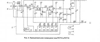
There are also so-called protective relays, which are almost identical in their purpose and are divided into semiconductor, magnetoelectric, polarization, induction and electromagnetic relays. This determines the difference in auxiliary relays according to the principle of their operation.
Previously, in most cases, relays with an electromagnetic operating principle were used. Nowadays, semiconductor ones based on semiconductor elements have become the most popular.
When the question arises of how to choose an intermediate relay, first of all you should pay attention to its characteristics. After all, in appearance this device is practically no different.
This is because the structure of a given electronic device is approximately the same, which includes a panel, a coil, a magnetic circuit, a pole piece, an armature, adjusting pins, a spring mechanism and a contact block. Relays are designed for both direct and alternating voltage.
Classification of types of intermediate relays
There are many options, let's look at the main varieties:
Relays are divided by switching type
- Minimum - reduce a certain parameter to a set threshold;
- Maximum – increases a certain parameter to a set threshold;
By functional purpose
- Combined - connecting a group of relays to solve a specific logical problem;
- Logical – work with the same parameters in discrete electrical circuits;
- Measuring – intervals of certain parameters are regulated.
By load control method
- Direct impact - relay contacts directly connect the load;
- Indirect influence - the load is connected through circuits of secondary elements.
By connection method
- Primary - connected directly to the circuit by contacts;
- Secondary - switched on through inductive or capacitive elements.
Intermediate relays in protection circuits have their own design features and are divided according to the following characteristics:
- Semiconductor - do not have switching contacts, the circuits are opened and closed by p-n-p and n-p-n junctions under the influence of control voltage. Varistors, thyristors, triacs and transistors are used as semiconductor elements.
- Induction - the control voltage in the winding is induced from an adjacent coil that is not connected by direct electrical contact;
- Magnetoelectric - the magnet occupies a stationary position in the structure, the coil with contacts on the frame rotates, closing or opening the circuit;
- Polarizing - work as electromagnetic direction of switching contacts will determine the polarity of the connection on the coil;
Definitions, classification
Intermediate relays will serve to unload the main contactors. Otherwise, the requirements for arc extinction will become strict, making production unprofitable. Powerful sources of electricity, thermal power plants, are built near natural resource deposits and have units with a capacity of hundreds to thousands of MW. The operation of such structures is unthinkable without relay protection circuits. The latter includes the object of consideration of the review.
In electrical engineering, a relay is a device that abruptly changes conductivity from infinity to zero and back under the influence of a certain factor. A factor is usually called an influencing quantity, usually current, voltage, power (including reactive), phase shift, circuit resistance, frequency, harmonic sequences. The parameter is formed by adding several others, called input ones. Relays are classified as follows:
At the connection location:
- Primary - directly constitute the protected circuit.
- Secondary - connected through inductive, capacitive coupling.
According to the method of action:
- Direct - directly opens the protected circuit.
- Indirect - act indirectly.
By purpose:
- Measuring - with adjustment within certain limits of the response level.
- Logical - triggered at one level, in discrete circuits.
- Combined – several measuring instruments united by a logical connection.
By the nature of the switching:
- Maximum – work to raise the parameter to a certain limit.
- Minimum – work to reduce the parameter to a certain limit.
According to this classification, we give the following definition:
In addition to intermediate ones, the logical family also includes: indicating ones (signaling the activation of other relays present in the circuit section), time relays (for counting intervals set by maintenance personnel), slow relays (triggered with a delay). It is customary to classify protection relays according to their operating principle:
- Electromagnetic ones work according to the law of action of a conductor with current on a compass needle, discovered by Oersted in the first half of the 19th century. The ferromagnetic core moves.
- Polarization ones differ from electromagnetic ones in the dependence of the state of the contacts on the direction of current flow.
- Magnetoelectric ones use a similar principle: a magnet made of a special alloy is stationary, the frame with the winding rotates, activating the contact.
- Induction motors are similar in principle to asynchronous motors; in a closed winding, the current is induced by a winding that feeds the current.
- Semiconductor relays are the most common, built on an element base with pn junctions, metal-semiconductor junctions.
Intermediate relays can be of any operating principle. Previously, they were mainly electromagnetic. Often used for reproduction and amplification of the signal of other relays. For example, there are many actuators, therefore, in excess of the control lines. Obviously, one relay will not cope with the switching task. Then an intermediate one is installed, each output controls one executive. The number of final relays increases significantly, and together they cope with the task.
Similarly, with a large current, the line can be divided into several branches, each connected to an executive relay. Controls the armful of the intermediate. Serves for simultaneous operation, protecting individual contactors from an excessively large arc that will certainly occur if the load falls on one cascade. An uncontrolled ionization process can easily burn switching and protective equipment. Will need some repairs. The intermediate relay, ensuring the coordinated operation of the others, protects the system from an accident.
Automatic relay
Explanation of the abbreviation of intermediate relays
To conveniently determine the functional purpose, number of contacts and other parameters, the relays have alphabetic and digital designations:
- P – intermediate;
- E – electromagnetic;
- 46 or (XX) – product series;
- 1 – pulse control signals.
Further designations may determine for what climatic conditions the product is adapted and the number of contact groups.
An example of how the symbols are deciphered
REP26-004A526042-40UHL4
- REP – electromagnetic intermediate relay
- Episode 26
- XXX – functional purpose and number of contacts
| appointment | Quantity | ||
| closing | opening | switching. | |
| 001 | — | — | + |
| 010 | — | + | — |
| 100 | + | — | — |
| 002 | — | — | ++ |
| 020 | — | ++ | — |
| 110 | + | + | — |
| 200 | ++ | — | — |
| 003 | — | — | +++ |
| 120 | + | ++ | — |
| 210 | ++ | + | — |
| 300 | +++ | — | — |
| 004 | — | — | ++++ |
| 220 | ++ | ++ | — |
| 310 | +++ | + | — |
| 400 | ++++ | — | — |
- 001 – means that the relay contains 1 switching contact, 010 – one breaking contact; 400 – four normally open contacts.
- A….D – wear resistance class of the materials from which the contacts are made;
- X – type of current in the winding of the electromagnetic coil, type of design for returning the mechanism to its original state,
1 – ~ current;
5 – direct current;
6 – direct current in the current coil;
- XX – two-digit digital code showing the design of mounting the relay housing on the surface and the method of connecting wires to the terminals:
| Code | connector | Wire connection method |
| 16 | —- | Solder |
| 18 | —- | "faston" |
| 76 | —- | seal |
| 21 | + | screw connections |
| 26 | + | solder |
| 78 | + | seal |
- XX – code indicating the magnitude, type of voltage, current in the coil winding
| Codes for electrical parameters of the closing coil | ||
| constant | ~ current 50 Hz | |
| 01…6 V 02…12 V 03…15 V 04…24 V 06…48 V 09…60 V 11…110 V 13…220V | 21…12 V 22…24 V 24…40 V 26…110 V 27…220 V 28…380 V 34…230 V 35…240 V | |
Codes from 01 to 13 indicate that the coils of these relays are DC with different voltages from 6 to 220V. Codes 21 to 35 indicate that the coils are rated for ~ I with U = 12…. 240 V frequency 50 Hz.
The last designation X indicates the presence of special elements in the design:
2 – manual relay switch;
5 – with manual manipulation and electronic relay position indicator for 24V products;
6 – with a manual manipulator and a diode to protect relays at 24V and less;
7 – the relay includes all three previously listed elements,
40 is the degree of protection from moisture and dust IP- 40...56..68;
UHL4 is a model for the corresponding climatic conditions, given for the north and middle latitudes. The letter “O” indicates that the product is adapted for the tropics.
REP26-004A526042-40UHL4 - this abbreviation indicates that the intermediate relay has 4 switching contacts with class A (wear resistance), direct current, contact connection with connectors, wires are secured by soldering, a 24 V coil, the design has a manual manipulator. Protection class IP – 40 for northern and middle latitudes.
Tip #1. Some people neglect the degree of protection of the product; relays have thin contacts and are sensitive to dust and humidity. Therefore, the degree of protection must be taken into account, especially in facilities with high humidity and dust. In explosive areas, it is recommended to use semiconductor products that do not spark during switching.
Despite the different designs and technical characteristics, all intermediate relays have basic common parameters by which compliance with the functional purpose is determined.
Device
These devices come in all types and sizes. From miniature relays with two contacts, to several dozen in a repeater relay. In all of them the design principle is the same. The intermediate relay device consists of an electromagnetic control coil, a magnetic core, a spring mechanism and a group of contacts. You can learn more about the design of the device by looking at the picture below:
The industry produces a wide range of devices for a variety of control voltages from 5 volts to 220. They can be designed for alternating “AC” voltage and constant “DC”.
Outwardly, they are practically no different. The only difference is in the design of the magnetic circuit. For alternating current it is made up of a group of plates, and for direct current it is solid. This is done to reduce heating losses in the magnetic core during the passage of alternating current.
As for the technical characteristics of devices, they are different for each type. For example, for the RE series they will look like:
For industrial purposes, blocks for intermediate relays are manufactured for installation on a DIN rail. Relays and sockets for them are also available with a wide range of connector types. This is done for ease of operation within the same device, when there are models of different voltages, and one type has not been replaced by another due to inattention.
Main technical parameters of intermediate relays
All relays, including intermediate ones, are evaluated according to the following parameters:
- Switched voltage value;
- Rated current value at switching contacts;
- Minimum switching current;
- Permissible short-term current through switching contacts;
- Interval of voltage value on the electromagnet coil;
- Power consumption of the switching coil;
- Closing time;
- Contact opening time;
- The wear resistance of contacts is assessed by the number of relay activations;
- The maximum permissible load power, which is connected through the relay contacts.
These are general parameters of technical characteristics; depending on the design and purpose, there may be additional ones. Let's look at specific technical characteristics using the example of REP - 26 different modifications.
| options | magnitude |
| Switching voltage range | AC 5–381 V DC 5–221 V |
| Rated current on contacts | 10.1 A9.1 A8.1 A6A |
| Minimum contact current | 0.06 A0.01A |
| Through current on contacts (A) | 161A |
| Interval of voltage changes in the control circuit | +5,1 %-15,1% |
| power consumption by the coil - at DC. current with 1-3 contacts - at DC. current with 4 contacts - with alternating current | 1.6 kV2.1 kV3.1 kA |
| Response time, no more. | 0.03 sec |
| Release time, no more. | 0.03 sec |
| Mechanical wear resistance. | 30 million triggers |
| Switching power - with alternating current - with direct current | 1.6kW3kW150W250W |
Using a relay
The assignment of an intermediate relay is performed when necessary:
- Close/open several interconnected circuits at the same time. Let's say one of the contacts needs to display an alarm signal on the device display, and the other needs to turn it off.
- Provide control over a more powerful device that switches (instantly changes parameters) in circuits with large current values. For example, in a drive it is necessary to apply voltage to the switch solenoid with a current strength that reaches a value of 63 A when turned on, but this cannot be accomplished using one auxiliary relay.
Here the question arises, how to connect an intermediate relay? First you will need to apply voltage to the auxiliary relay, which turns on the contactor with a higher power. Then he will switch the required current value.
Connecting an intermediate relay to circuits with loads for various purposes
Most intermediate relay models are adapted to standard mounting conditions, on a flat surface or on a DIN rail in a distribution cabinet. After installation, the relay can be connected to the electrical circuit of the system:
- First of all, the functionality of the relay is checked by connecting the coil contacts (13 and 14) to the power source, and a characteristic click of contact switching is heard.
This contactor diagram shows the position when there is no power to the coil.
When a voltage of 220, 24 or 12V is applied, contacts 9 – 10 – 11 – 12 are closed to the corresponding pairs 5 – 6 – 7 – 8.
In this connection diagram, the relay plays the role of a contactor distributing power to the load elements.
- The neutral wire is directly connected to one of the coil contacts;
- The phase is connected through a normally closed “Stop” button, which opens the circuit;
- Sequentially with the “Stop” button, the start button is turned on, which is open in the normal state and works to close the circuit;
- The second contact of the start button is connected to the phase;
- The phases are connected to normally open contacts;
- Load to normally closed contacts;
- One of the output contacts to the load is connected between the start and stop buttons; after starting, the circuit will provide a constant supply of voltage to the coil, the contacts will be closed. The relay and load will be disconnected when the circuit is broken by the “Stop” button.
The load can be a variety of electromechanical elements; to connect a high-power load, intermediate relays control the operation of a magnetic starter with contacts capable of passing large currents. Intermediate relays can be controlled by light sensors, a thermostat or a motion sensor, depending on the functional purpose of the circuit.
Control circuit for an electric heating system via a thermostat and a magnetic starter
The operating principle of this scheme is similar to the previous one. Only the start is carried out automatically by a thermostat, power is supplied to the coil of the magnetic starter, after which the heating elements are connected.
Connection diagrams
After the intermediate relay has been installed in the electrical cabinet, it should be connected to the electrical circuit. For this purpose, the contacts of the coil itself and direct contact elements are used. The relay usually has several pairs of NO normally open and NC normally closed contacts. The normal position is considered to be the absence of a signal to the coil. Since the coil does not have polarity, the contacts are connected arbitrarily.
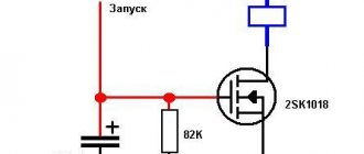
Such a device is installed in control and automation circuits. Located between the actuator (for example, a contactor) and the reference source. The figure shows the electrical diagram of the device:
The picture shows an intermediate relay without voltage supply. If you apply it, the contacts will switch. The voltage in the coil can be different: 220, 24 and 12 volts.
How to connect the device is shown in the figure below:
In some cases, an intermediate type relay is used as a contactor, then the installation diagram will look like this:
As you can see, the intermediate relay has three groups of contacts that control the load and one group to hold the current in the coil. You can install an additional contactor, then the device is connected first to the contactor.
This device can also be connected to a motion sensor. Thanks to it, it is possible to connect several powerful lamps to the motion sensor system. Installation occurs as follows: the winding of the device is connected to the sensor, and the power contact switches the load in the lighting system. How to install such a sensor is shown below:
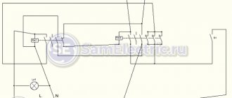
Another option for installing an electronic starter is to a thermostat. The diagram is shown in the picture (click to enlarge):
In this case, the thermostat and starter are connected in sequential order to the first phase and neutral wire (in the diagram they are designated as T1 and K1, respectively). The installation of the remaining contacts of the starter is carried out evenly between other phases.
Finally, we recommend watching a useful video on the topic:
https://youtube.com/watch?v=d6BA3PFlwCU
That's all I wanted to tell you about how to properly connect this device. We hope that the video instructions and intermediate relay connection diagrams provided were useful to you!
Consumer demand for relays from various manufacturers
There are a large number of relay manufacturers; among domestic ones, the products of FSUE NPP START in Veliky Novgorod, relay REP-26 004, REP-26 002, REP-26 003, are often used.
RP-21M, RP-21MN are produced at the Moscow and Cheboksary LLC "PKF Experimental Power Equipment Plant" in Cheboksary. These products are in good demand and are even counterfeited by Chinese competitors.
Tip No. 2 When installing Chinese models, be sure to test the contacts with a multimeter or other devices, in the initial state and after the relay is activated. It happens that the contacts stick, do not close or do not open.
On the right side is a variant of a Chinese fake.
Professionals recommend using imported models from manufacturers
ABB, Schneider Finder, Siemens, Electric, Relpol.
The wear resistance of the contacts of these products is much higher; failures in the control system of complex equipment can lead to production stops and costly repairs. Therefore, it is more rational to use more expensive but reliable relays.
Pros and cons of pulse relay
The popularity of pulse relays is due to the following advantages:
- Low price due to more affordable components.
- Load control with voltage up to 0.4 kV.
- No influence of overvoltage, interference and powerful electrical installations.
- Reinforced insulation between contacts and coil.
- No problems with cooling.
- Harmless to the atmosphere.
- Long lasting resource.
- Possibility of using a large number of switches.
- Low power consumption.
- Simple installation compared to main switches.
Flaws:
- Long response time.
- The appearance of radio interference when turning on / off.
- Accelerated wear of moving parts.
- Creating electrical interference.
- Loud noise during operation.
Errors during installation and operation
- One of the common mistakes is the incorrect choice of technical parameters of intermediate relays. Look carefully in which networks the relay is used, direct or alternating current, what voltage or current needs to be supplied to the control coil.
- Be sure to take into account the permissible current loads on the switching contacts, especially when the relay is connected directly to power high-power devices.
- Try to use a relay with the required number of contacts; models with a larger number consume more electricity on the electromagnetic coil.
Safety precautions during operation
There is a list of some measures that must be carried out for the correct and safe operation of the device.
Let's look at the list of these nuances:
- Personnel who service the relay must carefully check the functionality of the device and the condition in which it is located.
- Contact connections must be periodically cleaned from contamination.
- You must immediately remove the device from the network if damage is detected.
- It is necessary to comply with operational requirements for temperature, operating conditions and others.
- If problems occur, you should contact a specialist.
FAQ
- Is it possible to install a relay to control street lighting so that the motion sensor turns on one group of lighting fixtures and turns off the other?
One of the circuit options using a motion sensor
Of course it is possible, a detailed description of such a circuit requires a detailed consideration, but one thing is for sure, you will need to use a relay with a group of contacts for switching.
- Is it possible to use a relay with a large number of contacts to switch multiple loads without a magnetic starter?
A magnetic starter is definitely present in an electromagnetic relay, unless you use an additional starter with high-power contacts, which is controlled by an intermediate relay. This is possible provided that the relay contacts can withstand the load current for a long time.
What technical characteristics to pay attention to
When choosing an intermediate relay, you need to know what parameters to pay attention to.
The choice of device should depend on:
- The type of electrical current used.
- The number and type of contact used in the device.
- Maximum values of long-term contact currents.
- Power consumption.
- Relay sizes.
- Voltage indicator.
- Operating conditions.
- Resistant to the effects of vibration, noise and others.
- The periods during which work with contacts occurs.
Do not neglect these parameters, because the correct functioning of the relay will depend on them.
Indication (signal) relays
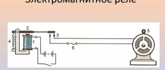
Signal (indicating) relays are used to provide signals (light, sound, indicating and others) about the occurrence of abnormal operating conditions in some part of the electrical circuit. Relays of type RU-21, operating on the electromagnetic principle, are one of the most common. The principle of its operation is that when current passes through its winding, the armature is attracted to the core, the flag, previously held by the armature, loses its support, under the influence of its own weight it turns along the axis and is installed with its painted surface opposite the glass window in the relay cover. This serves as a signal that the protection has activated. When the flag is turned, the contacts of the alarm circuit are simultaneously closed. The flag returns to its original position when the handle is turned.
Switching on from different places using relays and limit switches
At the request of reader Zoltan, I quickly sketched out a circuit that turns on and off two groups of lighting on the street and in the garage. In this case, pushbuttons, limit buttons and relays are used.
Scheme for turning on the light through the end buttons, Start, Stop buttons and relays
I took inspiration from here:
Algorithm and discussion of the scheme in the comments, starting January 16.
By January 26, after several intermediate options, the following scheme was born:
Lighting circuit on a relay with a motion sensor, limit switch and time relay
And then the author of the video sent Zoltan his diagram, here it is!
Automation circuit for turning on lights from different places