High-quality implementation of certain technological processes in the modern world is ensured by high-precision and expensive equipment. The operation of which directly depends on the quality of the supplied electricity and the condition of the power supply lines. Unfortunately, not all domestic networks are able to provide a safe operating mode for them, which creates a threat of breakdown. To prevent this, special protective devices are used - phase control relays (PKF).
They allow you to disconnect the load in case of any malfunction in the power supply network. Anything that may pose a threat to the equipment and affects the performance of its operation or the technological process is perceived as a signal to immediately de-energize and the control relay moves the switching elements to the off position.
Design and operating principle
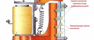
Rice.
1. Design of the relay using the example of the CKF-2BT device. Structurally, the device includes input and output contacts, indicators of normal power supply and emergency, regulators, indicated in the diagram by the corresponding numbers (Figure 1):
- Emergency indicator;
- Indicator of connected load power supply;
- Potentiometer allowing you to select the desired mode;
- Asymmetry level regulator;
- Voltage reduction regulator;
- Potentiometer that allows you to adjust the time setting.
Not all models provide the full range of settings for the above parameters. They depend on the purpose of the specific relay and the scope of application.
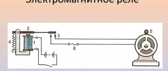
Rice. 2. Schematic diagram of operation
In normal mode, voltage is supplied to the power circuit from the EMF source E1 (Figure 2) to the consumer, be it an engine, a machine tool or other equipment. The phase control relay R is connected to the tap through the corresponding terminals, designated in the diagram as L1, L2, L3 and the neutral wire N. A logical circuit on transistors is assembled inside the device, which sends a signal from the output contacts to break the starter coil P to turn off. If necessary, the shutdown signal can be configured to both de-energize the consumer and disconnect the external electrical network.
In the event of an emergency - loss of one of the phases, short circuit, sharp increase in currents, the harmonic component of the electrical parameters of the network changes. To which the protection device reacts and sends a corresponding shutdown signal through the power circuits through terminals 24 and 21 to the contactor coil.
After the activation of power contacts in the practice of power supply to consumers, a natural restoration of the parameters of the supply network can occur, during which phase alignment will occur. In this case, the relay will return the contacts to the on position, due to which the automatic reclosure system is implemented and the voltage supply to the windings of the motor or other consumer will be resumed.
Using the “Start” and “Stop” buttons, you can manually control the power of an electrical device.
ATS circuit using phase control relay EL-11E.
The designs of relays that monitor phases, despite the wide range of products available, have a unified housing. In addition, the ELM reacts to the fact that U increases or decreases above the set parameter.
The installation of a neutral conductor on such devices is usually not provided, but this point is specifically determined by the design of the relay - the type of model.
Therefore, a phase control relay is simply necessary in this case. The voltage to the internal circuit is usually supplied from the first phase L1.
When problems occur in one of the phases, the responsible relay is activated, and the remaining phases continue to receive load. Correctly setting the restart time plays an important role in ensuring the normal operation of the device.
Related article: Energy audit is
Purpose of the device
Subtleties of choice When choosing a voltage phase control relay, you need to focus on the technical parameters of the device that is connected to the circuit. Various phase control relay circuits are given below.
In addition, when choosing, you need to take into account the modification of the relay. To which the protection device reacts and sends a corresponding shutdown signal through the power circuits through terminals 24 and 21 to the contactor coil.
Connection Recommendations
Burnout of household appliances included in a three-phase circuit also occurs. Purpose of the circuit: Monitoring the supply voltage and drive for open circuits using soft starters or a frequency converter. In the event of voltage asymmetry or a break in one phase, the built-in relay turns off after a time t specified by the user. The company's activities are based on the development and manufacture of industrial automation devices.
A stand is being assembled for this purpose. In practice, the product is used when equipment is frequently transferred, when changing the phasing may cause damage or incorrect operation. EKF Phase control relay RKF
Purpose and functions
This technology is used in a network of three-phase loads. It is most in demand for protecting synchronous or asynchronous electric motors, high-precision three-phase machine tools, high-tech electronics, and pumps. Please note that incorrect phase rotation will lead to low efficiency, overheating and reduced insulation levels, which can lead to breakdown.
Used for the following purposes:
- For switching converter equipment for which compliance with the phase sequence is important: power supplies, rectifiers, inverters and generators;
- For ATS systems (putting into operation backup power sources) or connecting an emergency lighting system;
- For special equipment - machine tools, crane installations, the power of which is no more than 100 kW;
- For electric drives of three-phase motors with a power of no more than 75 kW.
This device is not used for switching single-phase loads.
In general, the phase control relay is used for various industrial and household equipment and is a mandatory fuse for those control circuits that require constant monitoring of voltage levels and other parameters of external lines.
In three-phase networks it controls:
- voltage level, implemented, in the overwhelming majority, for equipment of this class in cases where its value goes beyond the established limits;
- phase rotation - will perform switching in the event of emergency phase sticking or if they are incorrectly located relative to the equipment supply inputs;
- phase loss – disconnects the consumer in the event of a phase loss and subsequent lack of voltage;
- phase imbalance - performs switching in the event of a change in phase or line voltage in relation to the rated value.
Advantages of phase control relays
Compared to other emergency shutdown devices, these electronic relays have a number of significant advantages:
- in comparison with the voltage control relay, it does not depend on the influence of the EMF of the supply network, since its operation is adjusted to the current;
- allows you to detect abnormal surges not only in a three-phase power supply network, but also on the load side, which allows you to expand the range of protected components;
- unlike relays that operate to change the current in electric motors, this equipment also allows you to record the voltage parameter, providing control over several parameters;
- is able to determine the imbalance of supply voltage levels due to uneven loading of individual lines, which can lead to overheating of the motor and a decrease in insulation parameters;
- does not require the formation of additional transformation from the operating voltage.
Unlike relays operating only on voltage, it provides effective protection against regenerated voltage generated by back EMF. In the event that one of the phase voltages disappears, the engine continues to gain a sufficient level of energy from the remaining two. In this case, in the de-energized phase, an EMF will be generated from the rotation of the rotor, which continues to rotate from two phases in emergency mode.
Due to the fact that the contactors of electric motors do not open from the relay during such operation, there is a risk of damage to the electrical machine with its further breakdown. The monitoring relay, in turn, is capable of detecting a phase angle shift, thereby providing full protection.
This function is especially relevant when the operating mode of the engine, in the event of its reverse rotation, can damage the rotated element or injure a worker. As a rule, this situation arises when changes are made during the de-energization of an electrical machine, changing phase loads, phase rotation order, and others.
Definition and purpose of RKF
The device is used to create a stable operating mode for an electric motor or electrical installation powered from a three-phase network, preventing the risk of breakdown. Any threat to electrical equipment, impact on the quality of work or the efficiency of the technological process is interpreted as a signal to shutdown, and the RKF de-energizes the switching elements.
RKF, depending on the modification, is intended to solve the following problems:
- Switching of electrical converter equipment, for which it is necessary to observe the phase order.
- Protection of units with power up to 100 kW.
- Commissioning of ATS systems, or connection of an emergency lighting structure.
- Protection of low power electric drives up to 75 kW.
The device is used to protect control circuits that require constant monitoring of voltage values and other parameters of the electrical network.
In three-phase networks, RKF controls:
- Voltage level. Maintains the specified range, turning off the power on the line when it goes beyond the limits on one of the network phases.
- Phase loss. Performs a shutdown.
- Phase rotation. In case of erroneous location or phase adhesion, it establishes switching of electrical equipment.
- Phase imbalance. Implements switching when the phase or linear voltage value changes relative to the nominal one.
It is advisable to locate such devices where electrical equipment is constantly switching from one line to another, or when installing electric motors, where a possible phase imbalance can cause an increase in temperature and combustion of the stator windings.
Specifications
Among the technical parameters implemented by the phase control relay, it is necessary to highlight:
- supply voltage;
- overvoltage control range;
- voltage reduction range;
- time delay limits for switching on after a power surge;
- time delay limits for switching on after a voltage drop;
- time spent on shutdown in case of phase loss;
- rated current at the contacts of the electromagnetic relay;
- number of contacts for performing switching operations;
- device power;
- Climatic performance;
- mechanical and electrical wear resistance.
The connection diagram determines the order of phase alternation, so normal power supply to the load is possible provided they are correctly observed at the installation and configuration stage. In this case, it is possible to adjust the switching delay for different operating modes of the device. Thus, for motors, at the moment of starting, it is possible to adjust the response delay time from 1 to 3 seconds to withstand starting currents.
The same applies to the possibility of adjusting emergency operation in case of phase overload, where the time before switching can be adjusted from 5 to 10 seconds.
Characteristics
| Options | Values |
| Switching wear resistance, number of cycles | 105 |
| Mechanical wear resistance, number of cycles | 106 |
| Mains voltage, V | 300 — 460 |
| Overvoltage adjustment range, Umax, V | 380 — 460 |
| Overvoltage delay time adjustment range, sec. | 0,5 — 5 |
| Voltage drop adjustment range, Umin, | B 300 - 380 |
| Range of adjustment of delay time by voltage drop, sec. | 1 — 10 |
| Relay response time in case of phase failure or error, no more than, sec. | 0,2 |
| Rated current of contacts, A | 5 |
| Power consumption, no more, W | 2 |
| Ambient operating temperature range, °C | -10 to +50 |
| Climatic performance | UHL4 |
Review of popular phase control relays
- RNPP-311 relay is one of the most popular and suitable for networks in the post-Soviet space. The abbreviation stands for voltage, imbalance and phase sequence relay. Modern modifications, in addition to standard parameters, are also capable of monitoring voltage frequency.
- OMRON K8AB this model monitors not only the reduction, but also the excess of the voltage level, thereby performing the functions of a limiter or arrester, and much more effectively. It has a number of modifications that differ in response threshold adjustments and technical parameters.
- Carlo Gavazzi DPC01 is distinguished by two relays on the output terminals of the device. It has several points for adjusting various parameters, and a mode switch. Provides 7 possible functions for setting delays, intervals or cyclic functions.
- EL-11 relay controls the parameters of the electrical network and can be used both in closed heated and unheated rooms. They can be installed in any position, but require protection from direct exposure to sunlight and atmospheric moisture.
Typical connection diagrams
In most cases, the manufacturer installs all the necessary data on the method of connecting a particular relay on the housing of each device. As an example, let’s take several circuits from well-known manufacturers:
Connection diagram RKF RNPP-311
The diagram shows the connection of the terminal row to the corresponding phases of the line L1, L2, L3 and neutral N. At the output, it is possible to obtain two control circuits “Output 1” and “Output 2”, differing in voltage levels.
OMRON relay connection diagram
Power is supplied through the input channels L1, L2, L3 and through the neutral N. At the output, there are two options: a three-phase three-wire system and a three-phase four-wire system, for working with the corresponding switch.
Connection diagram for RKF Carlo Gavazzi
Unlike previous versions, the input terminals L1, L2, L3 are powered through fuses. The parameter adjustment block allows you to adjust the corresponding operating mode and shutdown limits according to them. Two outputs with the possibility of manual switching send control signals to switch certain devices.
The last two diagrams demonstrate the operation of the secondary load disconnect circuits with the corresponding time delay across these terminals. As you can see, all connection diagrams have identical components designed to monitor all network parameters that can signal a failure in the power supply to three-phase consumers.