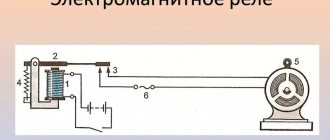
Relay functionality
The phase control relay (PKF) is designed to protect industrial and household electrical equipment from abnormal operating conditions of the power supply network. The device controls such parameters as:
- presence of all 3 power phases;
- shift angle between phases;
- voltage symmetry;
- the voltage value in each phase separately.
A common area of application of the device is the protection of asynchronous electric motors. They are unable to operate on 2 phases. In this mode, engines quickly fail. Using a monitoring relay, a circuit is implemented that turns off the motor when one of the phases is missing.
Note! In its task, the RKF resembles a three-phase voltage control relay. Both devices monitor the voltage in the network. But the phase control relay has a wider range of settings and capabilities.
Danger and consequences of misalignment
What is the danger of phase imbalance in the electrical network? Conditionally negative aspects can be divided into three groups:
- Harm to electrical receivers (devices, equipment): damage to them, reduction in service life.
- Harm to electricity sources: mechanical damage, increased electricity consumption, reduced service life of the source.
- Consequences for consumers: increased electricity costs, need for electrical equipment repairs, possible injury.
Due to the fact that electricity is distributed unevenly across conductors, electricity consumption in the electrical network increases significantly. A three-phase network that has developed asymmetry can reduce the service life of electrical appliances and household appliances.
If this is an autonomous power plant, then the oil and fuel consumption in this situation increases significantly, and the generator may break down. When one phase receives more voltage than the other two, electrical safety is compromised. And this can lead to various electrical injuries, as well as fire of electrical household appliances and the wiring itself.
As you can see, the consequences of this phenomenon are significant and their solution and elimination can lead to large material costs. In order to avoid such an unpleasant situation, certain measures should be taken in advance.
Expert opinion
It-Technology, Electrical power and electronics specialist
Ask questions to the “Specialist for modernization of energy generation systems”
Phase imbalance in everyday life Connecting devices with high power consumption to one of the phases inevitably causes an uneven load between the phases. Ask, I'm in touch!
Design and principle of operation
Most devices of this type are designed for mounting in electrical cabinets of protected equipment. The housing is equipped with a latch for mounting on a DIN rail. There are controls on the front for setting response limits.
The operating principle of the device is based on continuous monitoring of the network status. If the voltage or angle between phases goes beyond a critical level, the protective device will generate a shutdown signal and put the equipment out of operation. The shutdown occurs with a time delay. Its value is also adjustable.
UZOF device - 3M
This protection device consists of current transformers and a module. The module combines a power supply, a signal processing unit from current sensors, a logic unit and executive relays assembled on a common board. The device body is made of plastic for mounting on a dinrail or metal for bolting.
Block diagram of UZOF-3M
The power supply consists of 2 step-down transformers brand TPG-2-24V. It converts AC voltage 380 V to DC 48 V and is connected to terminals 1,2 in front of the input line contactor.
Internal structure of UZOF-3M
Power supply unit UZOF-3M
On the front side of the device there are terminals for connecting wires and 2 LED lamps are installed. The green indicator indicates normal operation of the protected equipment, and the red indicator indicates emergency mode. There is a seal sticker on the side wall of the product body. Removal or damage to the seal will constitute internal penetration of the device, as a result of which the manufacturer's warranty on the protective device will not apply.
Front panel UZOF-3M
The current sensor leads are connected to terminals 7-8, 9-10 and 11-12. Current transformers are made in the form of rings through which power conductors of phases A, B and C pass.
Pins 1-2 are used to connect the device to a power source with a voltage of 380 V. Terminals 3,4 are the connection point to the closing contact of the executive relay used in the control circuit of the input switching device. If dynamic braking of the electric motor is provided on the lifting mechanism, then an additional blocking contact (clamp 5,6) is provided to prevent operation of the UZOF-3M.
Types of RKF
Different RKF models have different technical characteristics. Therefore, each of these devices belongs to one type or another.
According to the settings options, relays are divided into 2 categories:
- Adjustable. It is possible to set the required response setting for voltage and time (EL-11, EL-12, EL-13, EL-15).
- Unregulated. Only factory settings are supported. An example of such a device is E-511.
Relay EL-13E
Ground fault protection
Protection against single phase to earth faults has two stages.
It is possible to operate each stage “on shutdown” or “on signal” with a time delay.
To implement the ground fault protection function, a first harmonic filter with filtering of higher harmonic components is used.
The following types of starting protection devices are provided:
- for zero sequence current 3I0 (non-directional protection);
- for zero-sequence current 3I0 (directional protection with the ability to block or output direction in the event of a break in the measuring circuits 3U0);
- by zero sequence voltage 3U0.
To implement directionality, the direction of the zero-sequence power is determined by the value of the phase angle between the current 3I0 and voltage 3U0.
When the protection is triggered, an alarm is issued.
Main technical parameters
Protective devices are used in a wide range of equipment. Therefore, their parameters can differ markedly depending on operating conditions. Of the most important technical characteristics of the phase control relay, the following are noted:
- operating voltage;
- response adjustment limits;
- response delay time;
- Operating temperature range;
- storage conditions.
Supply voltage
This parameter is selected depending on the supply voltage of the protected equipment. If it operates from 380 V, then a relay with a similar voltage value is selected. In addition, RKFs for 110 and 220 V linear voltage are common.
Important! Line voltage is the potential between phase wires. Usually it is 380 V. The phase voltage is between the phase wire and the neutral. Usually this is 220 V, like in an apartment socket.
Phase control unit for maximum line voltage 250V
RKF settings limits
Different phase control relays have different adjustment limits. If the equipment is designed to work with precise parameters of the supply voltage, then you can choose a relay with a narrow control range of 0.9-1.1 Un, which is suitable, for example, for electric motors.
If the accuracy of the supply voltage is not important, then a relay with a range of 0.7-1.3 Un is suitable. Such protective devices are suitable for three-phase heating devices and heating elements.
On/off delay
Many industrial consumers of electricity have a nonlinear starting characteristic. At the moment the engine or heating element is turned on, the starting current is tens of times higher than the rated current. Accordingly, the voltage drops during startup.
To prevent RKF from turning off the network when the voltage drops, an operation delay has been added to its operating algorithm. When the engine starts, the voltage drops below the permissible level, but the relay does not turn off the power for some time. This parameter can be adjusted using the control on the front panel of the device.
Working temperature
Extreme heat or cold has a detrimental effect on the electronic circuit of the RKF. An abnormal temperature value can lead to a drift in the characteristics of the internal radio components of the device, which will provoke its false alarms and shutdowns. Also, sudden cooling can cause condensation of water vapor inside the device, which will damage it. Therefore, it is important to observe the temperature regime of the RKF.
For example, devices of the EL-11E, EL-12E and EL-13E series are capable of operating at temperatures from –40 to +80°C. Therefore, they can be used in conditions of not too frosty winters.
Storage requirements
Every electronic device has both operating and storage conditions. Usually they are similar. Any phase control relay must be stored in its original packaging. If possible, avoid exposing the device to humid environments or extreme temperatures. During storage, vibration and unnecessary transportation of the relay should be avoided.
Protection and automation of 35 kV overhead line
PM RZA for 35 kV overhead line provides the following functions: protection:
- 4-stage distance protection against all types of short circuit;
- directional overcurrent protection;
- phase-to-phase current cut-off,
- protection against single-phase ground faults.
- tomatoes:
- LEVEL;
- APV.
Distance protection
Distance protection (DP) is the main selective protection against all types of phase-to-phase short circuits.
For phase-to-phase short circuits, complex resistances ZAB, ZBC, ZCA are used as a triggering element, which are determined from the linear voltages UAB, UBC, UCA and currents IAB, IBC, ICA:
Zab = UAB / IAB = Z1K = Z1ud LK; Zbc = UBC / IBC = Z1K = Z1ud LK; Zca = UCA / ICA = Z1K = Z1ud LK.
PM RZA "Diamant" implements four-stage distance protection against phase-to-phase short circuits. The shape of the characteristic of each stage of the DS can be specified in the form of a circle (or a sector of a circle) with an arbitrary location on the complex plane in the axes of active and reactive resistance. This is achieved through the appropriate selection of five parameters that determine the coordinates of the center of the circle, its radius, as well as the angular position of the initial and final radius vectors to determine the response sector.
In Fig. Figure 2 shows the possible shapes of distance protection response zones and their location on the complex plane.
Fig.2
In Fig. 2 the following notations are adopted:
- O (O _Re, O _Im) — coordinates of the center of the circle (or sector) of the triggering zone in the axes of active and reactive resistance;
- R is the radius of the circle (or sector) of the response zone;
- α is the angle between the axis of active resistance and the radius vector defining the beginning of the zone sector;
- β is the angle between the axis of active resistance and the radius vector defining the end of the zone sector.
The indicated angles, which determine the initial and final position of the radii of the protection response sector, are measured from the positive direction of the active resistance axis counterclockwise.
For clarity, the distance protection response zones are shaded. The implemented remote control provides for:
- individual adjustment of the response time of each stage;
- the ability to select operational or automatic acceleration of each stage of remote sensing with the corresponding response time;
- automatic blocking of distance protection in the presence of faults in voltage measuring circuits.
Review of popular phase control relays
There are dozens of models from domestic and foreign manufacturers on the market. Each of them has its own features and technical characteristics. When choosing an RKF, you need to take into account who produces it and for what purposes.
Zamel CKM 01
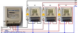
Three-phase phase rotation control relay with DIN rail mounting. Has a compact size. The width is standard for 1 module and is 17.5 mm. More detailed characteristics are shown in the table.
| Supply voltage | Single-phase 220 or two-phase 380 V |
| Maximum permissible voltage for contacts | 250 V |
| Internal relay power limit | 2.5 kVA |
| Output contacts | 1NO and 1NC |
| Maximum switching current | 10 A |
| Own consumption | 34 mA |
| Class of housing protection against dust and moisture | IP 20 |
| dimensions | 9x17.5x6.6 cm |
Zamel CKM 01 device for DIN rail mounting
RNPP 311
Relay from domestic. Installed in a panel on a DIN rail. It has a minimum of adjustment controls on the front panel, which makes it suitable for service even by untrained personnel.
| Rated supply voltage | 380 V |
| Mains frequency | 45-55 Hz |
| Own current consumption | No more than 35 mA |
| Voltage regulation range | 1.05-1.25Umax (for Umin similar values) |
| Fixed shutdown delay | 12 sec |
| Starter coil voltage | 110-380 V |
| Critical supply voltage values | 80-500 V |
| Working temperature | –25 +40°C |
| Climatic performance | UHL4 |
| Number of switching cycles at 5 A load | At least 100 thousand times |
Voltage monitor RNPP-311
ABB 1SVR750488R8300
ABB specializes in high-quality electrical equipment. The quality matches the price. The relay in question costs about 11 thousand.
| Control supply voltage | 450 V |
| Operating frequency | 50-60 Hz |
| On/off delay | 0.1-30 sec |
| Number of switching (changeover) contacts | 2 |
| dimensions | 85.6x45x104.8 mm |
OMRON K8AB
A compact device that has a slightly different purpose than the usual RKF. OMRON K8AB does not control voltage, but current. Therefore, an additional current transformer is required for its operation. The manufacturer positions the device as an ideal tool for monitoring current in industrial heaters and electric motors.
| Supply voltage (depending on modification) | 24 AC/DC current or 100-115 V or 200-230 V |
| Controlled current | 2 mA– 200 A |
| Number of controlled phases | 1 |
| Maximum output relay current | 6 A |
| Actuation hysteresis | 5-50 % |
| Model of the current transformer required for operation of the relay | K8AC-CT200L |
Important! Hysteresis, in simple terms, is a switching delay. It allows you to turn the relay on and off at different current values. This is necessary to prevent excessive switching and mechanical wear of the contacts. For example, the relay turns off at 5 A and turns on at 4. Or the temperature controller turns off the heater when the room is 24°C and turns on when 18°C.
Carlo Gavazzi DPC01
Multifunctional three-phase RKF with an expanded list of adjustments. Relays from this manufacturer are found in industrial compressor equipment. The front panel has standard voltage and delay regulators. As well as indicator LEDs, which facilitates human interaction with the device.
| Supply voltage | 24 V DC current or 230 alternating |
| Output current limit | 8 A |
| Adjusting the response delay | From 0.1 to 30 sec |
| Trigger voltage adjustment range | 2-22% of nominal value |
| Number of controlled phases | 3 |
| Degree of protection against dust and moisture | IP 20 |
| Installation | DIN rail |
| Limit voltage for output relay contacts | 550 V |
Euroautomatika FiF CKF-318-1
Belarusian phase control relay, which has proven itself as a simple, cheap and reliable solution for protecting electric motors. This RKF is triggered by a critical decrease/excess of voltage and the loss of one or more supply phases. Characteristics in the table.
| Operating voltage | 220/380 V |
| Output relay current limit | 8 A at 250 V |
| Contact type | 2NO and 2NC |
| Alarm indicator color | Red |
| Voltage lower limit range | 150-210 V |
| Upper voltage limit range | 240-280 V |
| Hysteresis | 5 V |
| Power consumption from the network | 1.6 W |
Relay for monitoring presence and phase rotation F&F CKF-318-1
Automatic transfer switching (ATS)
The ATS function is performed by the mutual actions of the PM RZA - SV and two PM RZA - BB. On the PM RZA-VV the AVR BB algorithm is implemented, on the sectional switch - the AVR SV algorithm. (PM RZA-SV, installed in the sectional switch cell, PM RZA-VV, installed in the 6-35 kV input cell.)
The initial information for starting and for triggering the automatic transfer switch is the voltage level Uab> UBC and UBHP controlled by the PM RZA - BB, the position of the input switch (RPO/RPV), as well as the presence of an enabling signal from the second input. Therefore, the AVR bb algorithm is the “leading” one, and the algorithm.
Algorithm AVR vv for PM RZA - VV
The ATS starts when the voltage trigger is triggered. In this case, a command is issued to the input switch, and after this command is executed, a switching command is issued to the PM RZA - SV with a time delay.
After the ATS PM RZA - BB is triggered, it controls the restoration of the voltage of the UBHP working source. When UBHP increases above 0.8 Unom, a turn-on command is issued to the input switch with a time delay, and 0.5 s after this command is executed, the PM RZA - BB issues a shutdown command to the PM RZA - SV with a time delay.
PM RZA - BB generates a discrete output signal to enable the ATS for the second input. A signal allowing the execution of ATS is issued in the presence of voltages UAB, UBC and UBHP exceeding 80% Unom.
Algorithm AVR sv for PM RZA - SV
PM RZA - SV carries out without delay the commands to turn on the sectional switch, which come from the first or second input. After turning on the section switch PM RZA-SV acts as input protection for the section that has lost the main power.
The functions of AVRVV AVRSV are blocked by the input discrete signal “Blocking AVR”.
Pros and cons of domestic relays
Equipment developers and adjusters periodically have to choose between domestic and foreign automation manufacturers. On the one hand, you want to do everything cheaper, and on the other, more reliable. To make the right choice, you need to consider the pros and cons of each option.
Advantages of Russian control relays:
- Low price. Imported RKFs cost at least 2 times more.
- The device can operate at temperatures below –25°C. Among foreigners, such endurance is less common.
- Russian EL series relays do not require additional 24 V power supply. Most foreign relays require an additional voltage source.
Devices produced by the Electrical Engineering Company Meander
Disadvantages of Russian RKFs:
- High heat dissipation. This indicates unreliability of power contacts or high consumption of auxiliary current.
- Incorrect operation of RKF analog circuits. Sensitivity to external interference.
- Outdated appearance. Although in the last decade there has been a “thaw” in terms of the design of domestic automation.
Technical characteristics of UZOF-3M
- Device supply voltage: alternating 380 V;
- Active power consumption does not exceed 5 W;
- Output relay response time is from 0.5 to 1 second;
- The current to the input contacts of the executive relay at a voltage of 380 V is no more than 3 A, at 48 V - 5 A;
- Current monitored by the device through current sensors of the drive of lifting mechanisms from 5.5 to 900 A;
- The degree of protection of the protection device against external influences is 1P30.
Circuit design
Within reasonable limits, the RKF connection diagram depends on the developer’s imagination. The standard device has 3 inputs for connecting phases. They are usually located at the top of the device. At the bottom there is a terminal block with 4 pins - NO and NC relay contacts. Some actuator is connected to them. For example, a more powerful relay, contactor or magnetic starter. It is possible to connect the load directly, but you need to take into account the current it consumes.
Relay design elements
Old Soviet relays for monitoring open-circuit and phase rotation were fixed to the mounting location using 2 screws. Modern devices are equipped with DIN rail mounting. This approach simplifies the repair and development of electrical cabinets.
The second design feature of the phase control relay is screw terminal blocks for connecting wires. The vast majority of protection devices are equipped with such contacts.
Adjustable controls
Regulators for setting the relay operating parameters are located on the front panel. This allows you to make changes without removing the device itself from the electrical panel. The regulators are made on the basis of trimming resistors. They do not stick out from the surface of the device. To rotate them, you must use any suitable screwdriver.
Some models of network imbalance protection relays are equipped with buttons and a display. In such devices, nothing needs to be rotated. However, it is somewhat more difficult to understand what is regulated and how. Especially without a user manual.
Electronic control device
Pin assignment markings
In terms of marking and designation of terminals, everything is the same as on any modern devices. The letters on the device body have the following designations:
- L1, L2, L3 - terminals for connecting 3 phases of the controlled network;
- NO/NC — output relay contacts;
- Umax is the maximum voltage threshold at which RKF will turn off the protected equipment;
- Umin - respectively, the minimum shutdown threshold;
- delay - the time after which the relay will operate.
Note! NC/NO (normal closed / normal open) - normally closed/open relay contacts. This marking is used on all modern equipment. The NC contacts are in a closed state and are short-circuited with a multimeter if voltage is not applied to the relay coil. As if it was just lying on the table. NO - opposite contacts. Without voltage they are in an open state.
Connection diagrams
It remains to consider how to connect the phase control relay to the existing line. We are not talking about private household cases using one power channel and neutral. Installation of a circuit breaker is justified in relation to the input to many consumers or the organization of energy supply to powerful equipment. It is produced according to the following scheme:
The device itself is pass-through and is installed after three-phase switches, on the line between them and consumers. The connection diagram for the phase control relay is quite simple, but needs clarification for each machine model. The contact sequences may vary, although the markings of the connecting lines are usually marked on the body of the device. In addition, there are relays equipped with an internal contactor. There are also models for which the use of a separate, external one is mandatory. The input conductors themselves are usually made in accordance with the following color coding:
The phase control relay to the end device is often carried out using additional protection devices that monitor the state of the internal line. For example, a connection diagram for an industrial pump:
There are some relays that contain contact groups in their design that are used in the “off” state. That is, the internal structure of the machine, turning off the flow of energy through some incoming channels, redirects them to others. The latter is quite interesting in terms of backup power supply to equipment. For example, if a problem occurs at one input, the relay will transfer consumers to another.
Installation diagram for using a backup power supply line:
To protect powerful and expensive equipment connected to full power supply, it is necessary to use a phase control relay. By cutting off the external power supply line when problems arising on any channel are detected, the machine saves the final and accompanying equipment from failure. At the same time, if the network characteristics return to normal, the relay will automatically connect the input to the consumers.
The only disadvantage of such protection is its focus on external conditions. Everything that happens on the line after the phase control relay has no effect on its operation. Accordingly, an automatic machine of this type must be used in conjunction with other means of protecting power grids.
Bottom line
At any industrial enterprise there are hundreds and thousands of three-phase asynchronous motors. No matter how modern and reliable the motor is, if during operation one of the phases feeding it disappears, it will burn out. The cost of the largest and most powerful engines is comparable to the price of a good car. A control relay costs much less than a motor. But it will definitely save him in the event of a phase failure. This explains the economic feasibility of installing RKF for engine protection.
Voltage quality is important not only for asynchronous machines. When there is a short circuit in the line, the voltage in one of the phases drops to almost zero. This mode of operation is unacceptable. RKF will notice a critical voltage imbalance and turn off the line. Thus, all consumers will be protected from abnormal operating conditions and subsequent losses.
With this in mind, the RKF is far from the least important protective device. It has not lost any relevance since Soviet times. On the contrary, with the development and complexity of equipment, the relay is only becoming more in demand, because it allows you to protect expensive electrical machines from breakdown.
Checking the operation of UZOF-3M.
Since the UZOF-3M device was available, I decided to check the serviceability of the protection device. I assembled the diagram that I gave above. For testing I used the equipment that was at hand. Here's the whole list:
Test scheme UZOF-3M
- 3-phase asynchronous electric motor with squirrel-cage rotor of the A4132M4 series, power 8.5 kW;
- Input circuit breaker brand FB 60 A (1);
- Magnetic starters PMA-311 (6) and PME-211 (7);
- Current transformers T-0.66 with a rating of 200/5 A (3, 4, 5);
- 2 two-button posts PKE-212 and KMZ-2 (8, 9);
- Three-phase induction electric meter SAU-4672M (2).
The response time of UZOF-3M after simulating an emergency mode was slightly less than a second. The device works properly!!!
Conclusions and useful video on the topic
The video is dedicated to the description and review of a single product from the EKF company. However, almost all manufactured phase control devices operate on the same principle:
With all the variety of devices on the market, it is difficult to determine any labeling standard. If foreign manufacturers label according to one canon, then domestic ones - according to another. Nevertheless, it is always possible to refer to reference data if an accurate decoding of the characteristics is required.
Would you like to share your own experience in selecting and installing voltage relays designed for phase monitoring? Do you have useful information that will be useful to site visitors? Please write comments in the block below, post photographs on the topic, and ask questions.
Features of various versions and their capabilities
There are two known types of devices used as part of linear three-phase systems: phase current relays and voltage switches. They have a standard design, determined by the requirements of regulatory documentation. Of interest is a comparative assessment of two types of modular devices.
Advantages of current relays
The undeniable advantages of current protective relays (TR) when compared with voltage monitoring devices are:
- independence from EMF, which constantly occurs during phase failures in the event of an electric motor overload;
- the ability to determine deviations in the behavior of an electric machine;
- the admissibility of monitoring not only the line itself (before the branch), but also the load connected to it.
Unlike TP, voltage monitoring devices do not allow the implementation of most of the listed functions. They are intended mainly for installation in linear circuits.
Phase failure detection
Failure due to phase loss is a common occurrence associated with a blown fuse or mechanical damage to the network. Under similar conditions, a 3-phase motor, for example, if one of the phases fails, continues to operate due to the power taken from the remaining two. Any attempt to start it again if one of the phases is missing will be unsuccessful.
The duration of its detection (reaction to overload) can be so long that during this time the thermal protection simply does not have time to turn off the unit. In its absence, the phase conductor break relay is triggered due to overheating of the electric motor windings. But this does not always happen, which is explained by the peculiarities of the operation of a device that is underloaded in one of the phases. In this case, the so-called “back EMF” begins to operate in it.
Reverse detection
The ability to detect phase reversal is required in the following situations:
- the engine is undergoing maintenance;
- significant changes have been made to the energy distribution system;
- after the power indicator is restored, the phase sequence changes.
The need to use a phase rotation relay is associated with the inadmissibility of engine reversal, which can damage the mechanism itself and also threaten operating personnel. The provisions of the PUE require the use of this device for any equipment, including conveyors, escalators, elevators and other moving systems.
Identifying Imbalances
Unbalance in electrical networks usually manifests itself as a significant difference in the amplitudes of the phase voltages coming from the district substation. Such an imbalance is observed in situations where, on the consumer side, the uniform distribution of loads across each phase is disrupted. Its presence in the system leads to a spread of currents in individual lines, which significantly reduces the service life of connected equipment (electric motors, for example).
This is explained by the fact that the so-called “sticking” of phases in the lines of inductive loads causes additional heating of the wires and contributes to the destruction of the insulation. All this justifies the need to install the specified model of phase protection relay in existing electrical networks.
Features of choice
When choosing control devices, their technical parameters are first taken into account. As an example, we consider the case of selecting a model for connecting an ATS, which involves the following procedure:
- The inclusion method is determined (with or without “zero”).
- The parameters of the selected device are determined.
- It is taken into account that when working with automatic transfer switches, it will be necessary to monitor the breakage and phase sequence.
To control the ATS, the delay time is set within 10-15 seconds.
Familiarity with individual modifications of control devices will help the contractor take into account the peculiarities of their functioning in specific circuits.
What is it for?
Application of phase voltage control relays
Special phase controllers are in demand in places where it is necessary to frequently connect to the power supply network and where it is important to observe their rotation. As an example, the situation is usually considered when the connected equipment is constantly transferred from one place to another. In this case, the probability of mixing up the phases of linear voltages is very high.
In some loads, incorrect alternation of them can lead to improper operation of the device and subsequent breakdown. Any unit connected to such a network for a long time is likely to fail. When operating such a device, you can easily make a mistake in assessing its condition, believing that the device needs repair.
general information
There are several types of phase imbalance relays, differing in the type of housing and their design features. Despite the large number of designs and abundance of circuit solutions, the operating functions of all models are almost the same. Installing a phase control relay in 3 phase circuits allows you to:
- extend the service life of electric motors;
- eliminate the need for restoration or repair work;
- reduce downtime due to three-phase motor failure and the risk of electric shock.
A phase relay installed in linear circuits guarantees protection of the unit windings from fire and single-phase short circuit.