Device diagram
Here is a diagram of a three-phase voltage control relay assembled on three single-phase Barrier voltage relays:
Three-phase voltage relay diagram
I emphasize once again that such a scheme is only suitable in cases where three-phase power is supplied to a switchboard from which a single-phase load distributed among the phases is supplied. When the load is three-phase (for example, electric motors), then the use of such a circuit can be dangerous, and option 1 (three-phase relay) must be used. Or change this circuit so that all three phases are turned off at once. To do this, it needs to be supplemented with a contactor, if anyone needs it, I’ll tell you in more detail.
For those who have read my previous articles, there is nothing incomprehensible in this scheme.
However, let me explain.
As usual, voltage is supplied to the meter through the input switch.
I have an article on connecting a three-phase meter, I recommend it. And here is the design of the three-phase Energomer meter.
And here is another article about the difference between three-phase voltage 380V and single-phase 220V.
Each relay (A1, A2, A3) operates on its own phase (L1, L2, L3). The relay outputs are the outputs of this circuit; I decided to designate them as R, S, T. Next, the phases arrive normally at their single-pole circuit breakers, and through them they disperse to consumers.
Circuit breakers F1, F2, F3 are not protective and are used simply as bypass switches. They are supposed to always be off, otherwise this whole circuit makes no sense. They turn on as a bypass only in emergency cases when the voltage relay does not work for some reason.
And there can be two reasons for this - relay failure and voltage going beyond the established limits.
However, there is a third reason, which is not mentioned in the instructions, and which I talked about in the previous article - when the voltage limits change, the relay turns off. Therefore, the bypass machine must be turned on when setting up the voltage relay, otherwise the load will be turned off during the setup time.
Three-phase voltage relay
Three-phase voltage relays belong to the class of devices that perform the functions of protecting consumers from dangerous deviations in the parameters of the supply network. The functionality of individual devices varies, but the list of main factors to which relays usually respond is generally general and looks like this:
• Deviation of the supply mains voltage from the nominal value upward or downward beyond the limits determined by the relay settings
• Violation of the symmetry of the supply voltage. This mode is monitored by comparing the phase voltage difference with the relay setting value. An extreme case of an asymmetrical mode is a break in one or two phases of the supply network
• Break of the neutral wire, characterized by the absence of phase voltages in the presence of linear
• Changing the phase sequence order. This situation most often occurs when workers of a network organization, after repairing or replacing a power cable, connect it without performing phasing, that is, simply mixing up the phases
• Deviation of the supply voltage frequency beyond the interval specified by the relay setting. This symptom is global in nature and indicates a shortage or excess of active power in the power system. Eliminated by means of system automation and load regulation of generators at power plants
The functional diagram of a voltage relay consists of three main parts:
• Measurement block
• Logic block
• Executive agency
The measuring part of the relay directly monitors the network parameters, transmitting measurement results to the logic block. This block compares the measured values with some basic values determined by the settings set on the relay.
Next, if the necessary conditions are met, a control signal is generated and sent to the executive body. The first two blocks of the relay circuit, depending on the design, can be implemented in one chip. Their division is conditional and is only functional in nature.
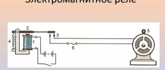
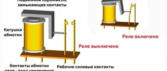
The executive body most often serves as an electromagnetic relay.
Important
The contacts of the relay actuator switch off the protected section of the network when the measured values reach the values specified by the settings. In this case, monitoring of external network parameters does not stop, since the relay is constantly connected to the supply voltage.
After the value of the critical parameter returns to normal (the network voltage returns to the permissible zone, phase imbalance is eliminated, etc.), the contacts of the actuator, after a specified period of time, reconnect the protected load to the network.
Thus, restoration of nutrition occurs without human intervention.
According to the method of switching the load by the executive body, voltage relays are divided into two types:
• Relays designed to switch the control coil circuit of a magnetic starter or contactor that turns off and turns on the load
• Relays directly switching consumer load circuits.
Photo 1. Three-phase voltage relay switching the contactor (starter) coil
Photo 1 shows a relay of the first type. At the top of the relay there are terminals for connecting the power supply. Contacts L1, L2, L3 and N are connected respectively to wires A, B, C and 0. At the bottom of the relay there are terminals of two contact groups (one normally closed and one normally open in each).
Figure 1 shows the connection diagram for this relay.
An electric motor is shown as the load, but in its place there may be a power input for an apartment or private house, as well as an electrical assembly to which a group of industrial consumers is connected.
Load switching is carried out by the power contacts of the KM contactor. The contactor coil is controlled by one pair of voltage relay contacts (terminals 5,6).
When the parameters of the supply network are within normal limits, the armature of the executive relay is pulled in, contacts 5 and 6 are closed. In this position, the contactor coil is energized, its power contacts are closed, and the load is connected to the power supply.
Advice
If the network parameters deviate by an amount greater than the permissible value, the logical device sends a signal to the executive relay. As a result, the relay is released and contacts 5 and 6 open. When contacts 5 and 6 are opened, the coil of the KM contactor is de-energized, as a result of which the power contacts of the KM open. The load is disconnected from the network.
In this case, the voltage relay continues to operate, monitoring the network parameters. When the network mode returns to normal, the logical block generates a signal to turn on the actuator, which leads to its operation and the activation of the KM contactor.
Fig 1. Connection diagram for the first type relay
Photo 2. Three-phase voltage relay directly switching the load.
Photo 2 shows a relay of the second type. Power input is carried out from above, to terminals N, L1, L2, L3. The load is connected from below, to terminals N, U, V, W.
The connection diagram is shown on the front panel of the relay. It follows from it that the actuator has three normally open contacts, each of them switches its own phase.
If the quality of the supply voltage is normal, the executive relay is pulled up, all three contacts are closed, the load is connected to the power supply.
When the parameters deviate to a value determined by the set setting, the logic is triggered, the relay is released, and the load is de-energized. Power restoration occurs in the reverse order, similar to that described for the first type of relay.
The relay contacts are capable of switching currents up to 63 Amperes, which is quite enough to power an apartment or a not too large house. On the front panel, the switches are clearly visible, with the help of which the relay settings are set.
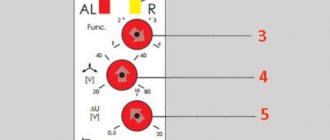
The leftmost switch sets the upper limit of the network voltage, upon reaching which the load is turned off. The position of the second switch determines the minimum voltage level, when reduced to which the load is also turned off.
The rightmost switch determines the period of time after which, after the mode is restored, the load is connected.
note
The types of voltage monitoring devices considered have an important difference. Relays of the first type can only be used in conjunction with a contactor or magnetic starter.
Relays of the second type perform their functions independently, without any additional devices. This circumstance makes the use of relays of the second type a more economical option and is more suitable for protecting apartments and private houses.
Entry 1
The customer has 4 inputs for two buildings, they all have differences, I will draw the attention of readers throughout the article.
First input. In the electrical room I saw this picture:
1 – electrical panel
At the top left is a panel with an input switch, a three-pole D80 circuit breaker.
More details about the inside of the shield:
1 – electrical panel interior
Above – Three-phase meter Energomera, digital voltmeter Digitop VM-3, street-generator switch.
Read about different ways to connect a generator in my article How to properly connect a generator. It tells you how to make manual and automatic transfer of reserve (ATR).
Here's a closer look at the first row, it will be very important for us, since all the connections will take place there:
1 – Counter outputs to switch
On the switch, at the top left, there are wires (white, blue, brown), into the gap of which we will need to connect our protection relay circuit. This place is even closer:
1 – Counter-generator switch
The flexible wires on the right side of the switch are from the generator, which is installed on the roof of the building.
Despite the fact that this electrical panel was assembled by a reputable company, a gross mistake is immediately visible - pay attention to the 25 Ampere machines:
1 – Gross mistake in choosing circuit breakers
And if on the right side of the photo a wire with a cross-section of 2.5 mm² can be understood and forgiven, then six wires of 1.5 mm² will no longer fit into any gate. Here I would lower the rating to 13 or 10A, but I need to deal with the load, and that’s not what I came to this facility for. For those who are interested, I discuss this problem in detail in an article about choosing machines for an apartment panel. There are also many links to relevant articles.
Okay, let's start assembling our circuit, which I put in a separate panel:
Electrical panel assembly process 1
The wire for installation was PV1, single-core, with a cross-section of 4 mm². Or rather, VVG4x4 dissolved into sinews. I connected it into the gap through a terminal connection with a screw, I couldn’t take a photo, there will be more examples below.
Here's what we ended up with:
1 – Final view of the three-phase voltage control relay
I printed operating and setup instructions for users on the back of the cover. I will give the text below.
Connection diagram and installation of voltage relay
Most relays are mounted in the distribution panel on a DIN rail. They can be installed in any position while maintaining their functionality. However, the connection diagram will be different for different models, so it is applied to the body of each device.
This makes it easy to connect the three-phase voltage monitoring relay to an electrical circuit, following the same rules for all types of these devices.
The input contacts are connected to the network through a contactor or a special starter. The conductors of all three phases are connected to the corresponding terminals located on top of the device. The phases are marked with the letters A, B and C, and the terminal for the neutral wire is marked with the letter N.
The lower terminals are numbered 1, 2, 3 and are connected in the following sequence:
- From terminal No. 1, the conductor is connected to one of the outputs of the coil located in the contactor.
- Terminal No. 3 is connected to any phase that bypasses the voltage relay.
- The second output of the contactor coil is connected to the neutral conductor of the three-phase network.
The connection of power elements is carried out as follows. Each phase supplying voltage is connected to the corresponding input terminal of the contactor. The conductors leading to the load are connected to the output terminals of the contactor. To connect neutral conductors, a common neutral bus is installed in the distribution panel.
The contacts of all connections should be as tight as possible, so it is advisable not to use twists, especially when connecting conductors to the contactor terminals. There are special tips that provide reliable contact. All connections are made using copper wires with a cross-section from 1.5 to 2.5 mm2.
Input 2
Here I photographed the input machine:
2 – Input automatic switch (switch) to the meter
Three-phase input differs fundamentally from single-phase. More details in my article.
And the electrical panel looked like this:
2 – appearance of the electrical panel
The meter has a magnetic seal. Why it is needed - I refer you to the article about Ways to Steal Electricity. But I say again - you need to live honestly!
2 – Magnetic seal on a three-phase meter
Appearance of the place where there will be a gap for connecting our voltage control relays:
2 – counter outputs
Closer, we are interested in the upper connection to the switch, on the left:
2 – wires between the meter and the switch, where the three-phase voltage relay will be connected
There's still a voltmeter in the way, but you'll have to leave it.
The process of assembling the second panel with three Barrier voltage control relays is shown:
2 – Three-phase voltage control relay based on Barrier relay
This is how this shield is connected:
2 – Connecting the voltage relay to the gap after the meter
This connection is very important because all power to the office goes through it. Therefore, I made it through screw-type terminal blocks (clamps).
The blue wires that previously went to the switch terminals now go through the terminals to the voltage relay panel. And from the Barrier outputs, the wires are connected directly to the switch terminals.
The connections in the panel are shown in the photo:
2 – Connections in the panel of the three-phase voltage control relay
The input cable carries three phases and zero. The current through the neutral wire is more than 100 times less than through the phase wires, so it can be neglected.
The second output cable uses three cores, the fourth is a spare (reserve).
As a result, the currents in the cables are the same, the cable is used at 75%, which is optimal from the point of view of overheating.
The second electrical panel took this form:
2 – Electrical control room with a new panel
A closer look at our shield:
2 – Panel with three-phase voltage control relay
Three-phase voltage relays – Novatek-Electro – production of electrical products
3-phase voltage control relay is a protective device designed to ensure the operation of three-phase AC consumers in the event of unacceptable fluctuations in the mains voltage, breakage, imbalance, phase rotation or sticking.
If the voltage in the network changes - the permissible values are exceeded or they decrease below the minimum level, any industrial electric motor and household appliances may fail. That is why the importance of installing a three-phase relay to control the electrical load is relevant and certainly justified.
Novatek-Electro is a manufacturing company that sells three-phase voltage control relays wholesale and retail. We offer favorable sales conditions to all our customers and dealers, including. Our products, which include a three-phase phase control relay, are popular and in demand due to their functionality, practicality and reasonable price.
Features of the device and scope of application
Protection of a three-phase electric motor from overload is necessary both in everyday life and in many industrial areas.
A three-phase voltage relay is used to ensure proper operation:
- Air conditioning systems;
- Refrigeration equipment;
- In equipment with an ATS circuit and any other equipment that uses an electric motor load.
Three-phase voltage relays from Novatek Electro are available in various modifications, taking into account the needs of problematic networks, where you can observe not only voltage interruptions, but also switching and pulse noise. The devices are equipped with a special delay during voltage sags, which makes the three-phase digital voltage relay effective in operation during short-term voltage sags.
Three-phase voltage relay devices are mounted on a standard DIN rail, they are lightweight and small-sized, which makes the process of installation and further maintenance of the device simple and safe.
The device is connected in parallel to the load, but what is noteworthy is that its operation does not depend on the load power. The three-phase protection relay at the outputs has two groups of contacts (closed and open), independent of each other and capable of switching loads up to 5A.
Product range
The three-phase voltage control relay is represented by the following model range:
- RNPP-311 - the device ensures the operation of the consumer under the condition of possible main types of accidents in the electrical network, such as exceeding permissible thresholds of mains voltage values, phase sticking or changing their sequence, full-phase failure;
- RNPP-311M – three-phase voltage control is performed under the same conditions as in the case of using the RNPP-311 device. However, the LED display panel in this model has been improved and, in addition to the presence of mains voltage, as well as the load state, indicates the type of emergency, which greatly facilitates subsequent user actions.
- RNPP-301 - in this modification, a three-phase voltage and phase control relay, ensures operation of the device in linear and phase voltage modes, has 6 potentiometers for setting parameters and adjusting the operation of the device.
- RNPP-302 - the device has a more advanced menu, which, in addition to the main functions, allows you to set a delay time interval in case of violation of the specified parameters, with the possibility of automatic start after restoration of acceptable network values.
- RNPP-311-1 - this device is two-channel and in addition to the main functions assigned to the three-phase voltage relay, it can control the network frequency.
- RNPP-311-2 is a two-channel device that monitors a 3-phase 380V/50Hz network with high accuracy, and is also equipped with signal indicators that provide information to the user about the full-phase network or partial phase loss.
The device comes with a warranty from the manufacturer, as well as full detailed instructions that will help the user to correctly install the device, maintain it in operation and correctly “read” the indications of the display panel.
Source: https://novatek-electro.com/produktsiya/trekhfaznye-rele-napryazheniya.html
Entry 3
Below are photos of the assembly and installation of the shield on the third input.
3 – assembly process.
Pay attention to the color sequence of the wires. Question: Which country am I a patriot?
I decided to use a flexible PVS 4x4 cable, because I had suffered in the first previous cases with solid cores. But in this case it is necessary to use tips, because... for screw terminals, which are used in Barriers, the strand is not comme il faut.
3 – Electrical panel assembled and installed
In the previous two versions, the wires went from top to bottom under the DIN rail, which is a little annoying.
Therefore, here I expanded the consciousness and the distance between the phases, and laid wires into the resulting gaps. The fact is that the Barrier block occupies approximately 2.8 modules on the DIN rail, and there will be gaps in any way. So why not use them for convenient installation?
3 – Shield with Barriers installed
3 – General view
3 – Complete
Input 4
4 – Appearance of the shield. A three-phase Barrier is connected to the gap through the screw terminal block
Closer. I think everyone understands why I use a terminal strip and do not connect directly to the meter terminals?
4 – Counter output – to terminal block
In previous versions, the panels were external, installed in electrical panels (utility rooms) and there were no installation problems. Immediately I had to make a built-in installation; I needed a drywall hacksaw.
4 – Inserting the shield into a plasterboard wall
4 – Final look
User instructions
As promised, I am posting instructions for the voltage relay, which can be seen in the photo.
I tried to write in simple language what it is, why and how:
Voltage control relay
Designed to automatically switch off the load if the voltage value exceeds the permissible limits. They work on each phase separately.
Automatic machines F1, F2, F3 are bypasses; during normal operation they MUST BE OFF (lower position). They are switched on in emergency cases, under the personal responsibility of the switcher!
Attention! When the bypass is turned on, the load is not protected from dangerous voltages!
During normal operation, voltage relays A1, A2, A3 indicate the voltage value in their phase. If the voltage goes beyond the set limits, the relays are turned off and the voltage readings flash. Turning on - approximately 1 minute after the input voltage has normalized.
If you need to change the voltage limits, please refer to the instructions. The bypass circuit breaker must be turned on when setting the voltage limits and delay times .
Thank you all for your attention, questions and comments, as always, I’m waiting for you in the comments.
Device and principle of operation
The relay is equipped with a housing made of special plastic; inside there is a measuring block and a contact group. The measurement module measures the voltage in the circuit, the resulting result is compared with a pre-programmed interval. If the numbers match, then the contacts of the executive unit are in a closed state, maintaining the functionality of the external circuit. The contact group does not require a continuous supply of electricity to hold the plates in closed or open states; current is supplied only at the moment of switching.
The meter constantly monitors the voltage; if the parameter deviates from the programmed interval, a control signal is generated. The pulse is transmitted to the contact group, which cuts off power from the equipment in the apartment or residential building. The design of the equipment provides for non-volatile memory in which information about the last emergency operation is stored. Voltage control is carried out by a microprocessor or a comparing device (comparator).
There are simplified relays from which the liquid crystal display has been removed. To change parameters, handles equipped with a measuring scale are used. The circuit provides signal LEDs that allow you to determine the reason for the contact group to operate. The electronic controller and mechanical relay part remain unchanged.
Voltage relay functions.
All protective relays are designed with an adjustable power-on delay timer. The device is necessary for the correct connection of equipment equipped with electric motors. For example, it is recommended to connect the refrigerator compressor to the network 1-2 minutes after an emergency shutdown. Depending on the manufacturer, timers are used that are designed to set a delay for a period of time from 15 seconds to 15 minutes.


