Let's measure the current and tell you how much
A current control relay (RCT) is an electrical device built on the principle of measuring the load current of an electrical network and outputs control signals when the measured value reaches threshold values, both upward and downward.
In other words, a current control relay is a modular device designed to monitor the amount of current consumed by the load so that, at the slightest deviation from the set values, it instantly sends a special signal to turn off and prevent overloads of electrical equipment.
Motor shaft load and current consumption
All the described processes have a common feature, namely: the use of asynchronous electric motors for various tasks. Thanks to this property, the task of automating these processes becomes not as difficult as it seems at first glance.
As mentioned earlier, as the load on the motor shaft increases, the current consumed by it also increases. Thus, it is the current that determines the current operating mode of the engine. Knowing the current consumption current, one can judge the condition of the equipment and the process as a whole. The motor nameplate indicates its rated current, corresponding to normal operation of the motor. Besides this, there are several other modes:
- Idling. Corresponds to engine operation without load (usually about 30% - 50% of the rated current).
- Overload. The motor consumes more current than the rated current (individually for each model, current is considered to be more than 110...120% of the rated one).
To monitor current consumption, the most suitable sensors are the Seneca T201 current measuring transducers, which will be discussed further.
Areas of use
RKT is used in various electrical installations to control the load of electrical equipment. It can signal or give impulses to shut down overloaded installations in networks with limited energy consumption. Or inform the duty personnel about an excessive load reduction, which may be a consequence of an emergency shutdown of equipment, broken power line wires or phases of electrical cables.
Depending on the tasks, the current control relay can be triggered by overvoltage or undervoltage in the electrical network. For this purpose, a special switch for these parameters is provided. The measuring cycle of the current control relay is quite short, so the device quickly responds to changes in its level.
Examples of technological processes
1.1. Grinding of solid product (crushing)
Figure 1 shows a typical crushing plant.
Figure 1 - Typical crushing plant
It consists of:
- a conveyor that supplies raw materials;
- directly from the crusher itself.
In both cases, electric motors are used. The raw material for the crusher is often rock.
Excessive supply of raw materials leads to overload of the electric motor that rotates the crusher. Insufficient supply, in turn, indicates inefficient use of the resources of existing equipment, because entails work in idle mode, and consequently a negative economic effect. To achieve the best efficiency, the material feeding process must be automated.
The control scheme in this case is quite simple: depending on the load on the crusher, the feed speed of the raw material, i.e. the conveyor, is regulated. This can be done using a frequency converter (FC). To do this, you need to connect a sensor to the inverter, which will act as feedback. This is enough to organize an independent control unit.
The operating algorithm of the system is as follows: the signal from the feedback sensor shows the current loading level of the crusher. Depending on this, the frequency converter will reduce or increase the speed of the feed conveyor motor.
Optical or ultrasonic sensors can be used as a feedback sensor (Figure 2).
Figure 2 — Determining the level in the crusher using an ultrasonic sensor
The sensor measures the level contactlessly and transmits a signal to a frequency converter. Accordingly, the higher the material level, the higher the load on the crusher engine.
However, such solutions have several disadvantages. If the crushing process is accompanied by the formation of dust, the use of optical sensors is impossible, since the dust interferes with the passage of the light beam. Ultrasonic sensors do not have this disadvantage and operate even in high dust conditions. However, both described measurement methods do not take into account the size of the rock fraction, on which the load of the electric motor most depends.
1.2. Maintaining consistency (stirring)
In processes involving mixing a product (for example, chocolate production), there is often a need to monitor the consistency (degree of thickness) of the medium.
Figure 3 - Typical industrial mixer
Consistency can be determined based on the density of the product being mixed. However, determining density is a complex task associated with a number of features:
- most density sensors (density meters) are designed to work only with low-viscosity liquids;
- Density meters require direct contact with the medium. Installing them in a container is problematic due to the presence of a mixing device;
- elevated temperatures limit the use of some sensors;
- A constantly running mixer introduces an error in measurements.
In this regard, density determination is often either abandoned or determined in the laboratory.
1.3. Extrusion using a screw press
Another type of process in which there is a need to monitor the operating modes of the electric motor is extrusion processes using screw presses. In this case, products are formed from polymer materials by extruding the melt through a special mold. One typical example of such a process is plastic extrusion.
Figure 4 shows a functional diagram of such a process.
Figure 4 - Functional diagram of the extrusion process
The raw materials are first loaded into the hopper, and then enter directly into the press using a feed screw. Asynchronous motors are used to rotate the feed screw and screw press.
Uneven supply of raw materials leads to the formation of air voids in the melt and unwanted cavities in finished products. And in case of excessive supply of raw materials, overheating of the bunker may occur due to the transfer of temperature from the molten mass.
Therefore, regulating the feed rate of raw materials from the bunker is necessary to produce high-quality products and increase productivity.
RKT device and principles of operation
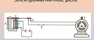
Like all other electrical devices, RKT can be electromechanical and electronic, alternating and direct current. To measure current, the relay must either be embedded directly into the controlled network or connected to it through an instrument current transformer (CT). Low-current relays are connected to the measuring circuit using measuring shunts. In order not to introduce errors into the measured network and reduce losses, the resistance of the embedded shunt should be as small as possible.
In electromechanical relays, the relay current coil is connected to the shunt, and in electronic relays the measuring circuit is based on microprocessors. When the current reaches the relay activation threshold (during overloads), the armature of the electromagnetic relay is pulled up, or the threshold element of the electronic key is triggered, producing a signal. When the current decreases, the electromechanical relay releases the pulled-up armature, causing the contacts to close.
An electronic relay works the same way. Relays with current transformers do not require insertion into the measuring circuit. The primary winding of the CT is the phase wire itself of the circuit being measured. A relay coil or measuring circuit is connected to the secondary winding of the CT. Usually the current transformer is built into the relay itself and the phase wire is passed through a window in its body. RKT can be equipped with time delay settings for operation, a time delay (0.5 - 5 sec) for tuning out the inrush current of electric motors and the magnetizing current of power transformers. The relay returns to its original state when the current returns to its normal value, or remains in the actuated state until action is taken by the personnel on duty (relay with memory). Electromechanical relays have hysteresis, i.e. The operating current is not equal to the release current, but is less than it by about 5%. In other words, the relay return coefficient (Ioperation/Irelease) is 0.95.
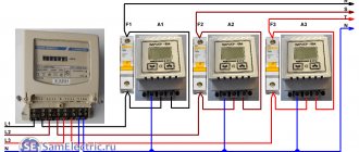
Modular single-phase current monitoring relays with integrated current transformer
Modular single-phase current monitoring relays with integrated current transformer.
Current relays are designed to signal excess current in the controlled circuit. These devices are also used to protect circuits and power supplies from overload and short circuit. Current relays measure its value in the controlled circuit and operate when the set value is exceeded.
BASIC OPERATING PRINCIPLES
A current relay is a device (usually electromagnetic or electronic) that responds to exceeding a controlled value in the input circuit. When the set value is exceeded, the output contacts switch and this signal is used to control alarm circuits or power switching (load shedding) devices. When the current drops below the set value, the current relay returns to its original state, and its output signal is processed by the automation circuits that control the power circuits.
Let's consider a current relay with an integrated current transformer from various manufacturers.
A relay with an integrated current transformer allows you to stretch a wire through the front panel of the product in which the current is measured. The relay is powered by a wire with controlled alternating current.
The connection diagram for all relays of this type is the same.
The benefit in this case is the universal supply voltage of the device.
Current relay RT-15M (Moscow)
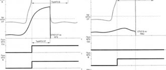
The RT-15M relay is designed to control current in electrical circuits. The relay operates with an adjustable time delay when the current value is higher than the set value.
If the measured current value exceeds the set threshold value, the executive relay will turn on after counting the time delay set by the potentiometer “t”. When the current decreases to a value of 0.9 Iset, the relay turns off without delay. If during this countdown the current value returns within the set values, operation will continue without switching the executive relay. The magnitude of the operating current is set by the “threshold” potentiometer within 10...100% of the maximum current value.
Controlled Current:
2.5…25A, 4…40A, 10…100A 50Hz
Features: Power is supplied from a controlled alternating current wire, which is passed through a side hole in the relay housing.
Load priority relay RPN-1 (St. Petersburg)
RPN-1 priority relays allow you to limit electricity consumption in electrical systems with a limited maximum power. For a certain time, the total current of the electrical system is measured and if the electricity consumption exceeds a set value, the priority relay will turn off the non-priority load.
Current measurement range (by version)
2.5-25A AC
4-40A AC
10-100A AC
Let's consider a current relay with an integrated current transformer in which the power supply is galvanically isolated from the measuring circuit.
This design reduces the thermal loss of the product compared to products with a built-in shunt, and also increases the current range and galvanically isolates the measured area.
Current relay PRI-32 (Czech Republic)
PRI-32 monitoring relay is designed to monitor current levels in single-phase AC circuits. Smooth adjustment of the supplied current allows the relay to be used in applications that require indication of passing current; it is also used as a selection relay. The output relay is normally open. When the configured current level is exceeded, the relay will close. The benefit in this case is the universal supply voltage.
- Current measurement range: 1-20A AC
- universal supply voltage: AC 24 - 240 V and DC 24 V
- power supply is galvanically isolated from the metering circuit
- excess current - the current passing through the control wire should not briefly exceed 100 A
- output contacts 1x changeover 8 A
Current relay PRI-52 (Czech Republic)
PRI-52 relay is used to control current strength in single-phase AC circuits. Smooth adjustment of the supply current makes the relay suitable for many different electrical installations. The output relay is normally off. If the specified current level is exceeded, the relay will close after the configured delay. When returning from an error state to a normal state, hysteresis occurs. The range of the PRI-52 can be increased using an external current transformer. The advantage of the PRI-52 is that the hole for the passing wire is located under the cover level in the switchboard - the passing wire is thus out of reach for inappropriate manipulations in the switchboard.
- can be used to record current up to 600A from an external current transformer
- smooth adjustment of the supply current - AC range 0.5 ... 25A
- smooth delay adjustment via potentiometer - adjustable in the range 0.5...10s
- supply voltage AC 230 V; output contact 1x changeover 8 A (AC1)
Current relay RT-40U (St. Petersburg)
RT-40U current control relay is designed to issue a control signal when the measured current exceeds the set value. The current monitoring relay is used to monitor overloads of machines, electric motors or other electrical equipment, to monitor consumption, overcurrent protection, diagnostics of remote equipment (short circuit, low or high current consumption). The measuring range can be extended using a standard current transformer.
- Three current measurement ranges (0.1-1A, 0.5-5A and 2.5-25A)
- The response threshold is adjustable from 10 to 100% of the maximum current range (1A, 5A or 25A)
- High overload capacity in long-term mode in accordance with the range (1A - up to 4A, 5A - up to 15A, 25A - up to 400A)
- The response delay of the executive relay is adjustable from 0.2 s to 20 s
- 1 changeover contact 16A, 250V
Current relay RM17JC (Schneider Electric)
Relay RM17 JC00MW is designed to control high current (overcurrent). If the current level exceeds the operating threshold set on the front panel of the relay, the device contacts close and open when the current level falls below a value calculated as the operating threshold minus hysteresis. When Y1 terminal is connected to A1 (+) terminal, the relay output action is reversed. Thus, the relay contacts open if the current level exceeds the operating threshold set on the relay front panel, and close when the level falls below the hysteresis value.
- supply voltage: 24-240 V AC, 24 V DC
- current measurement range: 2…20 A
- 1 changeover contact, 5A
Other current relays:
PRI-51, RKT-1, RKT-2, RKT-40, PR-612, PR-613, PR-615, RM35 JA, CM-SRS.1, CM-SRS.2, RM35 JA
Our company presented you with an overview of current relays with an integrated current transformer of domestic production and foreign manufacturers. Every year more and more powerful electrical appliances and equipment are used, and therefore electrical products for protecting electrical networks are also being improved. To prevent failure of expensive electronics and electrical equipment in a network with unacceptable parameters, it is better to turn it off, and the signal for this is given by a current relay.
Types of RKT and their technical data
RKT are divided into devices:
- AC and DC;
- voltage 12, 24, 36, 48, 220, 400, 660V;
- the strength of the measured current is from several amperes to hundreds of amperes (in a relay with a CT);
- with time delays from 0 to tens of seconds;
- single-phase and three-phase;
- relay protection degree 1P20/1P40 (to ensure personnel safety).
RCTs are mounted on distribution boards, lighting panels, electrical control panels on a DIN rail or on a flat surface. All switches for selecting relay modes (operating current and time delay settings) are located on the front panel of the device. Switching on and off the load is carried out either by the contacts of the relay itself, or with the help of switching devices that provide switching of high currents. RCTs are produced both by domestic industry:
- RKT-1 AS100-265V (single-phase, alternating current from 100 to 26 V);
- RKT-1 AS400V (same for 400V);
- RKT-1 DC24V (24V DC).
Likewise with foreign companies:
- CM-EFS/25 (AC and DC from 3 to 660V, ABB company).
Which is better: stabilizer vs relay
Often, instead of connecting an electrical control relay in the instrument panel, it is recommended to install a voltage stabilizer in the house. In some cases this is justified. However, there are a number of nuances that you need to remember when choosing one or another option for protecting electrical appliances.
From a functional point of view, the stabilizer not only equalizes the voltage, but also turns off when the voltage is too high. A voltage relay is an exclusively protective circuit breaker. The former seems to include the functions of the latter.
But compared to the RKN stabilizer:
- more expensive and noisier;
- more inert in case of sudden changes;
- there is no possibility to configure parameters;
- takes up much more space.
When the input voltage is reduced so that the output of the stabilizer has the required indicators, it begins to “pull” more current from the network. And this is a direct way to burn the wiring if it was not originally intended for this.
The second serious drawback of the stabilizer compared to the control relay is its inability to intercept a large voltage surge in the event of a zero break.
Just half a second at 350-380 volts at an outlet is enough to burn out all the equipment in the house.
Note
And most stabilizers cannot adapt to such changes and pass high voltage, turning off just 1-2 seconds after the start of the peak.
In addition to stabilizers and relays, overvoltage and undervoltage releases can also be used to protect the line from voltage drops in the network.
But their response time is longer than that of RKN. They also do not turn on the power automatically, working more like an RCD.
After a power failure, these versions will need to be restored manually.
Some manufacturers
- ABC;
- iemens;
- Legrand;
- EKM (Russia);
- Meander (Russia).
For detailed information on the service “Assembly of switchgear switchboards”, please contact our office by phone
Payment methods for completing and assembling electrical panels:
For the convenience of our Customers, payment for the completion and assembly of electrical panels can be made in the following ways:
Handbook for setting up secondary circuits - Setting up DC network insulation monitoring devices
Page 14 of 58
Setting up DC network insulation monitoring devices DC network insulation monitoring is carried out according to the diagram shown in Fig. 2.23. When checking devices, the resistance of resistors Rl, R4 and R is checked. The resistance values should be 1000 Ohms (resistance R is the sum of the resistances of resistors R2 and R3). The voltmeter V=£2 has two scales: voltage and resistance, so it serves as both a voltmeter and an ohmmeter. The internal resistance of the voltmeter must be at least 1000 Ohm/V. The voltmeter and KV alarm relay are selected and configured in accordance with the data in table. 2.13. The switch diagram and circuit diagram for measuring insulation resistance should correspond to Fig. 2.23, a and b. The insulation resistance of the network connected respectively to the positive Table 2.13. Technical data of voltmeters and DC insulation monitoring relays
| Mains voltage, V | Voltmeter scale, V | Relay used | |||
| Trigger | |||||
| Type | Compound | Voltage, V | Current, mA | ||
| 220 110 60 48 24 | 150—0—150 75—0—75 30—0—30 30—0—30 15—0—15 | RN-51/M78 RN-51/M78 RN-51/M34 RN-51/M34 RN-51/M34 | Sequentially Parallel Sequentially Sequentially Parallel | 32 16 6,4 5.1 3.2 | 2,1 2,7 2,1 5.3 |
positive and negative buses, is determined by the formulas that are given on the dial of the potentiometer (Fig. 2.23, c), after performing the following operations. When the insulation deteriorates to “+”, as can be seen from the readings of the double-sided scale of the voltmeter-ohmmeter, the switch is set to position /, while rotating the handle of the potentiometer RP, set the needle of the VQ device to the zero position, according to the fixed scale of the potentiometer (Fig. 2.23, c ) determine K\, and from the mobile one - Ki. Without touching the handle of the potentiometer RP, set the switch SA to position II, then the FQ device shows the insulation resistance of the DC system R3. Rice. 2.23. DC system insulation monitoring circuit The insulation resistance “+> and at “—” can also be calculated using the formulas. Similar operations are performed if the insulation has deteriorated at “—”, only in the reverse order: first, the zero position VQ is set at position SA II, and the countdown the device is carried out in position SA I, then using the above formulas you can check the calibration of the voltmeter-ohmmeter VQ and the scales of the potentiometer RP. After checking the circuit elements, setting the alarm relay, connecting the ground to the voltmeter-ohmmeter and the relay, the operation of the ground alarm is checked by simulating insulation deterioration. To do this, alternately connect the ground to the “+” and “-” busbars through resistors of various resistances. The voltmeter-ohmmeter reading on the ohmmeter scale must correspond to the resistance of the connected resistor. With a resistor resistance of 40 kOhm (for a 220 V network) and up to 9-10 kOhm (for a 48-110 V network), the “ground in the DC network” signal should operate. It should be remembered that if the insulation on both poles deteriorates simultaneously, the signal may appear at a lower resistance of the resistors.
- Back
- Forward
COMPENSATION TYPE CURRENT SENSORS
Compensating current sensors allow non-contact measurement of direct, alternating and pulsed currents in the ranges of ±5... ±1200 A. The structure of the devices is shown in Fig. 3.
| Table 1. Characteristics of current sensors based on various technologies | ||||||
| Current sensors | Absorption | Electric | External | Frequency | Voltage | Relative |
| power | insulation | nutrition | range | offsets | price | |
| Resistive DC | Yes | No | No | < 100 kHz | No | lowest |
| Resistive AC | Yes | No | No | > 500 kHz | No | low |
| On the Hall effect | No | Yes | Yes | < 100 kHz | Yes | average |
| open | ||||||
| On the Hall effect | No | Yes | Yes | > 1 MHz | No | high |
| compensatory | ||||||
| Current transformers | yes (for AC) | No | No | fixed | No | high |