How logic bus protection works
6.19.
Logical bus protection (LBP) Purpose: Section-wide protection that ensures disconnection of the input
a circuit breaker with a shorter response time when a fault occurs on a bus section.
It is used for MKZP servicing input switches of distribution devices.
The LZSh algorithm is used in switchgears to analyze the location of the fault - on the busbars or on the outgoing line - and, accordingly, quickly turn off the input circuit breaker when there is a fault on the busbars.
The LZSh algorithm works with the “Start MTZ” signal generated by its own MTZ block, as well as the “Start MTZ” signals of the MCZP blocks of bus section devices (hereinafter referred to as “Start MTZ ssh”). Attention - for correct operation, the algorithms must be configured to operate from the first stage of the overcurrent protection.
When the signal “Start MTZ” of its own unit occurs and there are no signals “Start MTZ ssh” (i.e. a short circuit occurs on the buses, and not on the outgoing line), after a time delay specified by the time setting, “Work. LZSh" to turn off and block the switch and alarm. The indicator of the unit displays the message “PROTECTION TRIP.LZSH”, the LEDs “OFF” and “EMERGENCY” flash on the front panel. A blocking of the subsequent switching on of the switch is introduced, which is then released by pressing the “RESET” button. An emergency protocol “Activation.LZSh” is generated.
When there is a short circuit at the outgoing connection, the operation of the LZSh is blocked by the “Start MTZssh” signal.
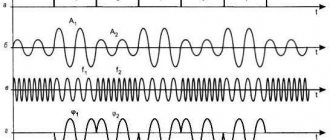
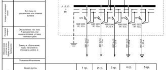
An example of the LZSh operation is shown in the figure. The top graphs show the currents of the input (top, green) and output (bottom, red) switchgears. Below are shown the signals “Start MTZ” of the outgoing switchgear (SS), “Start MTZ” of the input switchgear (in the examples given, the “Start MTZ” signals are configured to operate from MT31), as well as the LZSh triggering signal.
The graphs on the left side show processes during a short circuit on the outgoing line. At the same time, the current of the switchgear increases - both for RU-OT and RU-V it becomes higher than the MT31 setting, the algorithms are triggered, generating the corresponding signals. The LZSh algorithm, receiving both signals, does not work. The emergency process stops after the outgoing line is switched off by its own protection MT31. In this case, RU-V remains turned on, since the temporary setting MT31 RU-V, set for reasons of selectivity of the protection, is greater than the setting MT31 RU-OT.
The graphs on the right side show the processes during a short circuit on the switchgear buses (between RU-V and RU-OT). In this case, the RU-V current increases above the MT31 setting, and the “MTZ Start” signal is generated. The RU-OT current remains below the MTZ setting, so the “Start MTZ ssh” signal is not generated. The presence of the “Start MTZ” signal in the absence of “Start MTZ ssh” is a condition for launching the LZSh algorithm. Since during the time delay Tsr LZSh - the time setting of the algorithm - the signals did not change - the current of the input cabinet did not fall below the set point, and the outgoing lines did not increase, the RU-V is switched off via LZSh.
It should be noted that if the LZSh algorithm is enabled, the shutdown will occur only after the MT31 RU-V setting has expired, as shown in the top graph.
For correct operation, the algorithm must be entered and configured to trigger from MTZ 1.
Setting T is an independent time delay, selectable zero or with a short delay to tune out interference and random operations. But in any case it should be lower than the MT31 response setting
MTZssh1/MTZsshO – service setting, for correct operation of the algorithm must be set to MTZsshO position
Input/output of protection is performed by the “input/output” software switch.
Source: sinref.ru
Microprocessor protection and automation devices for networks 35-10(6) kV RZL-02
- Protection, automation, control, measurement, registration and signaling of 35-10(6) kV connections: overhead and cable power lines, as well as motors.
- Backup protection of 110 (220) kV equipment, including protection of dead-end overhead lines 110 (220) kV.
Protection, automation, control, recording and signaling devices for 35-10(6) kV lines
- Possibility of flexible device programming
- Implementation of the required configuration within 14 days from the date of placing the order
- Design reliability
- Ease of maintenance
- Modern digital technologies and microprocessor technology
Application area
- Switchgear for auxiliary needs of power plants
- Distribution substations of network enterprises
- Power transmission lines of distribution networks
- Industrial and utility companies
- Oil and gas complex facilities
- Traction substations of railways and subways
- Mining industry enterprises
| Main functions | |
| Protection | Automation |
| MTZ - maximum current protection ZNZ - protection against single-phase earth faults ZMN - minimum voltage protection ZPN - overvoltage protection ZOF - protection against phase failure and load unbalance ZSN - undervoltage protection | AVR – Automatic switching on of reserve AR – Automatic re-closing of breaker failure – Reservation of failure of circuit breakers LZSh – Logical protection of buses AFR / CHAPV – Execution of commands from an external frequency unloading device. Frequency control. |
Measurement, registration, alarm
- Indication of effective values of currents and voltages of fundamental frequency (50±5 Hz)
- Indication of effective current values 3I0 in the frequency range from 45 to 150 Hz
- Indication of phase shifts between the main harmonics of the phase current of each phase and linear voltages between the other two phases
- Calculation of zero and negative sequence currents
- Frequency indication
- Registration and storage of oscillograms, emergency event parameters
- Calendar and astronomical time clock function with non-volatile power supply
- Signaling of the device status and protection activation is carried out using freely assignable relays and LEDs, as well as via the ACS channel
Versions of RZL-02 depending on the protected connection or electrical equipment:
- RZL-02-VV – for 35 kV overhead line input switches
- RZL-02-L – for cable and overhead lines 10(6) kV
- RZL-02-SV – for sectional switches 35-10(6) kV
Protection functions
Overcurrent protection (overcurrent protection) Multi-stage, with acceleration, with voltage starting and U control
| Input rated three-phase current, In, A | 5 |
| Range of current operation and reset settings, A | 0,05-125 |
| Discreteness of settings for operating current, A | 0,01 |
| Power consumption by the current circuit per phase, VA | no more than 0.4 |
| Determination of the shift angle of currents and voltages | 0°…360° |
| Angle of maximum sensitivity | 0°…90° |
Protection against single-phase earth faults (SFG) Non-directional, with independent characteristic, with one or two time delays.
| Setting range for zero sequence current, A | 0,01…4 |
| Discreteness of settings for zero sequence current, A | 0,01 |
Changing settings programs RZL-02 provides storage of two sets of settings and program function keys. Programs are changed by sending a discrete signal to the RZL-02 discrete input via a command via a serial channel.
Protection against asymmetry and phase failure of the supply feeder (ZOP) Is implemented by calculating the negative sequence current I2.
Back-to-back logic bus protection algorithm
Nikolai Vasilyevich Chernobrovov wrote: “Creating selective high-speed protection is an important and difficult task in relay protection technology. These protections are quite complex and expensive, so they should be used only in cases where simpler time-delay protections do not provide the required speed of action...”
The logic of modern digital protections is currently built by implementing algorithms that are analogues of existing relays of previous generations. And although these algorithms are reliable and time-tested, unfortunately, they are not always optimal.
The PUE regulates: “As a protection for busbars of power plants and substations of 35 kV and above, differential current protection without time delay should, as a rule, be provided, covering all elements that are connected to the system or section of busbars...”.
Experience shows that the high cost of modern digital relay protection terminals pushes the customer in some cases to abandon differential busbar protection and search for alternative options. This trend, coupled with the wide capabilities of microprocessor devices, gives reason to think about this topic.
We had the opportunity to take part in the design of a substation, on the medium voltage side of which the possibility of two-way power supply was provided. And although the use of differential protection in conditions of multilateral power supply seems, of course, the best, due to the high cost, it is impractical. Logical bus protection in its classical sense is not applicable, since its action may be non-selective. For example, during a short circuit in a transformer.
Today, small-scale energy is actively developing. To ensure uninterrupted power supply, for example, to consumers in the gas industry, low-voltage gas turbine units (up to 12 MW) running on associated gas are connected to low-voltage buses. The situation is similar in the oil industry, and not only. In this case, the number of connected generators can exceed 5 pieces. If there is a short circuit in any of the supply elements, the selectivity of the classical LZSh may be disrupted. In addition, if the section switch is constantly on and there is a short circuit on the protected section with the first time delay, the section switch will be switched off and only with the double input.
It is known that in multilateral power supply conditions, directional current protection is used. In its simplest form - with a positive sequence power direction relay. Directional current protections based on electromechanical and semiconductor elements have their drawbacks. The first is the presence of the so-called “dead zone,” which predetermined their use mainly for protecting lines. The second is long time delays, especially on power supplies (however, this applies to all current protection with time selectivity).
In microprocessor-based protection devices, the “dead zone” effect is eliminated, for example, using a memory “circuit”.
It is proposed to use a power direction device to ensure selectivity in the protection device of any obvious or potential “source”. It should provide two control actions - depending on the sign of the power - “one’s own” or “someone else’s”. “Own” - when the power is directed from the protected element, “foreign” - into the protected element.
Types of arc protection
There are two types of arc fault protection: mechanical (valve and membrane) and electronic (photothyristor and fiber optic).
Valve sensing protection
This type of protective device contains a sensor in the form of valves with switches, which is triggered by an increase in air pressure as a result of the appearance of an arc. An increase in pressure in the cell causes the cap to be knocked out, which closes the contact of the sensor (valve), and a protective disconnection of the equipment from the network occurs.
The valve-type PDZ is easy to design and maintain, has an affordable price, and is reliable at short-circuit currents above 3 kA. But due to the fact that the relay reacts not to the arc itself, but to its consequences (increased pressure), then at low currents the short circuit does not have a very high sensitivity and a somewhat long response time.
Membrane arc protection
The membrane-type ZDZ is equipped with hoses that are connected to the compartments of the switchgear cells. The hose system is integrated through back pressure valves and connected to a membrane switch, which is activated when the air pressure generated by the arc increases.
Photothyristor arc protection type
Refers to an electronic type of protection against arc faults; it reacts to a flash from an electric arc using a sensor, which uses a semiconductor device - a photothyristor.
Arc protection based on photothyristor sensors has relatively high sensitivity and speed of response. However, they cannot be installed for a complete overview, and it is difficult to take into account organizational nuances when monitoring serviceability. Also, photothyristors may trigger falsely due to leakage currents, direct sunlight or switched on lighting lamps.
Fiber optic remote sensing
The next representative of electronic protection against arc faults is the fiber-optic type of PDZ - the most modern and high-quality. The sensors are placed in the input compartments, the withdrawable element, and in the cable compartment. The fiber-optic communication line serves as a transmission link when the sensor is triggered by an arc flash. The microprocessor terminal, having received a signal from the sensor, issues a command to turn off the switches to eliminate the short circuit.
Fiber optic remote sensing
Important! These relay protection devices are endowed with the advantages of photothyristor protection devices and do not have their vulnerable characteristics. The high cost of fiber optic devices is justified by efficiency, reliability and quality
The best representative of the protection presented is the Lime device, which has the most effective technical characteristics:
- response (speed) – 0.7-0.9 ms, that is, 10 times higher than in conventional devices;
- response start time – 40 ms;
- duration of operation after shutdown (inertia) – 3 s;
- Thanks to the ability to connect three sensors, a viewing angle of more than 1800C is achieved.
In order to save money on the installation of optical protective protection, a rational option for constructing protection is chosen, combining zones of the same name: compartments of the bus bridge, switches, current transformers. Depending on the characteristics of the scheme, combining zones of different names is also used.
Arc protection is a necessity when operating power equipment. This is especially required in enterprises, institutions and organizations, on whose uninterrupted power supply important human and technical factors depend.
The use of a reliable and high-quality electric arc protection system will eliminate risks from the operation of equipment of strategic importance, as well as the life and health of a large number of people.
Relay protection
Distinctive features of the operation of power systems are:
- Rapidity;
- Interconnectedness;
- Coordination of procedures for the production, distribution and consumption of electrical energy.
To control all processes in the power system, special automatic control tools are used. All used automation devices, according to their purpose and scope of application, are divided into two classes:
- Local and system technological automation;
- Local and system emergency automation.
The purpose of system technological automation is to ensure the normal operation of the equipment, namely:
- Starting turbine-generator units and putting synchronous generators into operation;
- Automatic regulation of voltage and reactive power on power plant buses;
- Automatic frequency regulation and ensuring the power plant’s given load mode;
- Optimal distribution of electrical load between blocks;
- Voltage regulation in the distribution network;
- Regulation of frequency and power flow.
System emergency automation is designed to prevent and most effectively eliminate the consequences of accidents, namely:
- Protection of electrical equipment from short circuits and non-standard operating methods;
- Automatic switching on after the fault has been eliminated;
- Independent activation of backup equipment;
- Automatic frequency unloading;
- Automatic elimination of asynchronous mode;
- Self-preventing stability failures.
The main role among emergency equipment devices is played by relay protection, which evaluates the behavior of the electrical supply system and its components in modes of large negative influences and sharp jumps in electrical characteristics.
Negative reactions can be caused by a number of factors, namely:
- Breakdown or short circuit of insulating elements of power lines due to lightning influences or when they are contaminated;
- Breakage of wires or lightning protection grounding due to ice freezing or large fluctuations;
- Mechanical deformation of supports, damage to insulators, jamming of wires;
- Incompetent actions of operational personnel;
- Factory defective equipment.
The main objectives of relay protection are:
- Independent detection of a faulty element and its subsequent isolation. The protective system provides a signal to trip the switches of this component, creating acceptable operating conditions for the untouched part of the energy system;
- Independently detect unusual operating conditions and use measures to correct them. Deviation from the usual mode is primarily caused by various overloads, the shutdown of which is not necessary. Having unloaded the equipment, the protection communicates this error signal to the operating personnel.
Logical bus protection
Bus logic protection circuit
Logical bus protection is a consequence of the modernization of relay protection. The main area of application of LSSH are radial distribution networks from 6 kV to 35 kV. The main reasons for using bus protection logic are the short time required to disconnect a short circuit on the buses, as well as its low cost. The response time of the lsh is 0.1-0.15 s.
The advantages of digital bus protection over other devices include:
- According to the principle of operation, differential protection involves the use of auxiliary windings of current transformers at all section connections that need to be connected to the differential relay. In the event of a short circuit, the relay itself adds the currents coming to the buses from the power feeders and the currents of the outgoing connections and, if unbalanced, gives a signal to block the relay. This is the complexity and lack of reliability of the equipment;
- Overcurrent protection of supply lines is widely used to protect busbars. According to the operating principle of this protection, its response time is 1-3 seconds. Over such a long period of time, the current arc during a short circuit will cause irreparable damage to the equipment.
Logical bus protection is an integral part of any microprocessor terminal relay protection equipment.
Among all the protections used in power systems, LSH is qualitatively different in its reliability and speed. Logical protection equipment will gradually replace the electromechanical element base, which will only have a positive impact on the safety of energy systems as a whole.
The need for arc protection is caused by the imperfection of current
Despite the requirements of paragraphs of the PUE clause 3.3.31, clause 3.3.42 on the use of automatic reclosure of busbars and automatic transfer switches after the elimination of short circuits inside the switchgear compartments, today design organizations and operating enterprises reasonably doubt the need to fulfill these requirements and prefer blocking the automatic reclosure of busbars and automatic transfer switches during when the switchgear arc protection is triggered. This decision is justified by the negative experience of operating organizations in using automatic reclosure of medium-voltage busbars. Is this approach justified? Do existing protection solutions ensure the shutdown of arc faults in a time during which no critical damage occurs inside the switchgear? Current step protections cannot be used as fast-acting protection against arc faults due to the large time delays at the supply connections (usually more than 0.5 s In order to reduce the operating time of current protection at supply connections, logical bus protection (LBP) is used, the operating principle of which is based on the transmission of blocking signals from protection devices for outgoing connections. However, in this case, the protection response time exceeds the permissible value. The LZH time delay is usually at least 100ms.
LZSH has a number of disadvantages:
- no tripping during a short circuit in the “dead zone” of the cable connection compartment of the switchgear input cell;
- possible failures of LZSh associated with excessive blocking of protection in the event of feeding the short circuit from powerful synchronous electric motors (in order to eliminate this drawback, it is possible to use a more complex protection circuit using voltage circuits and controlling the direction of power on outgoing lines);
- possible failures of LZSh in networks with low-resistance resistive grounding of the neutral, in which the ground fault current during a short circuit to the switchgear frame may be less than the current protection setting.
Thus, LZSh also cannot be used as high-speed protection of switchgear against arc faults.
LZSh – logical bus protection, principle of operation, purpose, implementation
Logical bus protection is currently included in almost any microprocessor relay protection terminal.
Its task is to turn off a short circuit on the switchgear buses in the minimum possible time, limited only by the own response time of the electronic part of the terminal. Typically this is from 0.1 to 0.15 s. Why is LZSh the most effective protection for this part of the reactor plant? Let's consider possible options for eliminating short circuits on tires.
The first option is to use differential protection. To implement it, additional windings of current transformers will be required at all connections of the section. They need to be connected to a differential relay, the task of which is to add up the currents entering the buses from the power feeders and the currents at the outgoing connections at the moment of a short circuit. If the unbalance current exceeds the set value, the relay gives a shutdown command.
The system turns out to be very complex, but with complexity its reliability decreases.
In addition, current transformers with additional windings are more expensive. Restrictions are imposed on testing relay protection and automation connections: if a test current is accidentally supplied to it, the protection will operate falsely.
The option of using incomplete differential bus protection is also not very effective.
It differs from the previous one in that current transformers are used only for supply lines and powerful consumers. But its use, among other things, is very limited.
The next opportunity to protect buses is overcurrent protection of supply lines. In principle, this is done in the vast majority of cases. But this type of protection has a significant drawback. To detune the MTZ from short circuits at outgoing connections, its time delay must be greater than that of the MTZ of consumers. In practice this is 1 – 3 seconds.
As the short-circuit current increases, every second of its action becomes fatal for electrical equipment. The longer the arc burns, the more destruction it causes.
Reliability of LZSh
Unlike other protections, LZSh rarely trips when checking relay protection and automation equipment by electrical laboratory personnel. When working on outgoing connections, the blocking signal, although it arrives at the inputs of the power line terminals, does no harm. Only a failure in operation is possible if the factor of the presence of a test current on the outgoing feeder and a real short circuit on the buses coincide, but the probability of such an incident is small.
When checking the relay protection and protection of the supply line, nothing will happen. If the buses receive power through a section switch or another power line, then their logical protections operate independently of the power line being tested; it is impossible to reach them from there.
In this way, LZSh compares favorably with differential protections, operating in the coverage area of which you can mistakenly cause a large-scale man-made accident.
Failures in the operation of LPS are mainly associated with short circuits at the terminals of current transformers. Differential busbar protection detects short circuits on them using relays installed in each phase. Any of the relays, when triggered, will give a command to turn off. In the case of LZSh, it’s the other way around: if a short-circuit current flows through the current transformer of any of the phases of the outgoing feeder, a blocking signal will be generated.
Therefore, if during a short circuit in a complete cell the arc jumps over the transformer terminals, the LZSh failure will occur. And the short circuit will be eliminated only with the overcurrent time delay of the supply feeder.
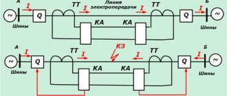
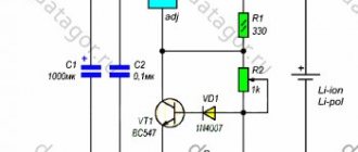
Figure 1 shows the simplest diagram of logical protection of busbars in combination with overcurrent protection at the 10 kV input.
In the event of a short circuit on the busbars or on the outgoing line, protection is activated at the input from the supply transformer (relay KA is activated).
The overcurrent protection at the input is adjusted in time from the protection of outgoing lines and acts to open the circuit breaker in two cases:
— failure of protection or outgoing line switch;
- short circuit on busbars.
Figure 1. Bus logic protection circuit
In the event of a short circuit on any outgoing line (CL1 - CLn), current relay KA1 is activated in its circuit and current relay KA in the input circuit. The KA1 contacts block the protection action on the KL relay.
When there is a short circuit on the buses, the KA relay in the input circuit is triggered and none of the KA1 relays in the outgoing line circuits are triggered. Relay KL is activated and acts to open the input switch with automatic reclosure prohibited.
The scheme is quite simple, but has a number of disadvantages:
1. When testing the protection of any connection, the entire circuit is broken and the protection is disabled.
2. A large number of series-connected elements reduces the reliability of the circuit as a whole. Contact failure in any current relay or connecting wires leads to protection failure.
The diagram shown in the following figure is more convenient and reliable. Current relays of all outgoing lines are connected in parallel. To exclude accidental activation of the protection during checks, the relay protection and protection of connections is switched on in series with the contacts of its own switches. In this case, the KL relay acts as a blocking one.
Figure 2. Bus logic protection circuit
What does LZSH consist of?
Bus logic protection elements are not concentrated in one place. This is a system that combines protection terminals for supply and outgoing lines.
Outgoing lines, when launching their own protections (usually MTZ), generate a blocking signal LZSh. For this purpose, one discrete output is allocated to each of them. Signals from all outgoing lines of the section are sent to the discrete inputs of the power feeder terminals. For transmission, a power and control bus system is used, which is part of any modern switchgear. This is where the entire constructive part ends. All that remains is to set the correct LZH settings on all terminals and set the assignment of discrete inputs and outputs.
The terminals of the section switches receive the LZSh blocking signal from the connections of both sections that they connect. For this purpose, different digital inputs are used.
Behavior of LZSh during external short circuit
In the event of an external short circuit, the overcurrent protection of the connection at which it occurred is triggered. Naturally, the shutdown will occur after the time delay specified for the given fault current has expired.
But, if there is a LZH, the terminal will perform one more task: it will issue a signal to block it.
It will arrive at the terminals of the feeders feeding the section.
On these terminals, if the MTZ is triggered, the LZSh will start. It is in them that it is configured to turn off; on outgoing elements it is not needed, their task is only to transmit a signal that the short circuit is in their coverage area, and they are ready to eliminate it.
The appearance of a blocking signal will cause the LZSh at the supply line terminals to stop and shutdown will not occur.
In case of failure of the overcurrent protection of the outgoing line, the short circuit will be eliminated by the overcurrent protection of the supply feeder or breaker failure. LZSH is not responsible for refusal.
Operation of LZSh during short circuit on tires
If a short circuit occurs on the switchgear buses, no blocking signal will be received from the outgoing lines, since the short circuit current does not pass through them. The launch of the overcurrent protection of the supply bus lines in the absence of a blocking signal will lead to an instantaneous action of the LZSh to disconnect the connections. Moreover, all switches through which power is currently supplied will turn off independently of each other. If, in addition to the input, a sectional switch is turned on, then the LZSh will work on it as well.
The protection is called logical precisely because its work is associated with the analysis of the location of the short circuit in the system: if not a single terminal of the outgoing line sees the short circuit, then it is on the buses.
The area covered by the protection is limited to the installation sites of current transformers of all connections of the section. In this way, it is similar to differential bus protection, implemented in a classical way. When the LZSh is triggered, an ATS prohibition signal is generated for the damaged section.