Features of regulators for primary transformers
The battery charging current is 10% of its capacity. This means that a battery with a capacity of 60Ah is charged with a current of no more than 6A. The charging voltage when the car is running is 14.5V. Given the required margin, the charger should be capable of delivering 10A at 16V.
A voltage reserve is necessary to regulate and limit the charging current.
In different models of devices it is done in different ways:
- Additional resistances. They turn on after the diode bridge. The simplest design, but with the largest dimensions.
- Transistors. High adjustment accuracy, but the most complex circuit that requires good cooling of power transistors.
- Thyristor control. Simple diagrams. The adjustment is carried out by a thyristor switch in the primary winding circuit or by thyristors installed instead of diodes in the rectifier bridge.
Electromechanical (servo-drive) devices
If it is elevated, it moves down. The role of the current collector slider in stabilizers is performed by graphite brushes. They maintain the output voltage with high accuracy (up to 2%), and its adjustment is smooth. These are their main advantages. Some stabilizers, for example, those produced, use not one, but two graphite brushes. This increases the contact area. This device regulates voltage faster.
Some electromechanical models with a power of over 30 kW can be equipped with an additional transformer. Despite the presence of moving parts, devices of this type operate silently. They have a high overload capacity.
By choosing this equipment, you can significantly simplify the calculation: add a quarter of it to the obtained average power of the equipment and thus obtain the characteristics of the future stabilizer. This means that it is permissible to take the minimum reserve of stabilizer power and pay a lower purchase price.
| Manufacturer | power, kWt | Input voltage, W |
| Resanta | 0,5-100 | 140-260240-430 (three-phase) |
| Elitech | 0,5-30 | 160-250280-430 |
| Caliber | 0,5-30 | 160-250 |
| Sturm | 0,5-30 | 140-250 |
The mains voltage is adjusted using a slider that moves along the winding. At the same time, different numbers of turns are used. We all studied at school, and some of us may have dealt with a rheostat in physics lessons.
An electromechanical voltage stabilizer works on this similar principle. Only the slider is moved not manually, but using an electric motor called a servo drive. It is simply necessary to know the structure of these devices if you want to make a 220V voltage stabilizer with your own hands according to the diagram.
Electromechanical devices are highly reliable and provide smooth voltage regulation. Characteristic advantages:
- Stabilizers work under any load.
- The resource is significantly greater than that of other analogues.
- Affordable cost (half lower than electronic devices)
Unfortunately, with all the advantages there are also disadvantages:
- Due to the mechanical design, the response delay is very noticeable.
- Such devices use carbon contacts, which are subject to natural wear and tear over time.
- The presence of noise during operation, although it is practically inaudible.
- Small operating range 140-260 V.
The current is adjusted by connecting more turns of the transformer. In case the device does not have time to react in a timely manner to excessive voltage, a relay is provided in the stabilizer device.
A stabilizer made independently has its pros and cons, which you should definitely know about. Main advantages:
- low cost;
- maintainability;
- independent diagnostics.
The most obvious advantage is its low cost. All parts will need to be purchased separately, and this is still incomparable with ready-made stabilizers.
If any element of the purchased voltage stabilizer fails, it is unlikely that you can replace it yourself. In this case, all that remains is to call a technician to your home or take him to a service center. Even if you have some knowledge in the field of electrical engineering, finding the right part is not so easy. It’s a completely different matter if the device was made by hand. All the details are already familiar and to buy a new one, just visit the store.
If anyone has previously assembled a 220V 10kW voltage stabilizer circuit with their own hands, it means that the person already understands many of the intricacies. This means that identifying the malfunction will not be difficult.
Diagram and purpose of a thyristor voltage regulator for a transformer
The current flowing through the battery during charging is determined by the internal resistance of the battery, its emf and the voltage at the output of the charger. To change it, in addition to other methods, you can adjust the voltage on the primary winding. The most convenient way is to use a thyristor regulator.
Battery charging models
Chargers are divided into three groups:
- Launchers. Designed to start the engine with a discharged battery. It is not recommended to use it to charge batteries - insufficient voltage and lack of adjustments.
- Chargers. Designed to charge batteries. They have manual or automatic adjustment.
- Starting chargers. Can perform both functions.
Operating principle of a thyristor regulator
A thyristor has two states - open, in which it passes electric current, and closed. This element opens when current flows through the control electrode and remains open as long as current flows through the thyristor. The alternating voltage in the network has a sinusoidal shape. A thyristor connected to the load circuit opens at a certain moment of the half-wave. This is called the “opening angle”. As a result, current does not flow through the electrical device all the time, but only after the element has transitioned to the open state. This changes the effective voltage across the load.
Important! A voltmeter measures the RMS value. For reliable operation, the permissible voltage of the thyristors must correspond to the maximum voltage, which is 1.4 times greater. For a household network this is 308V.
Stabilization of household voltage
The desire to provide stabilized voltage to the household network is an obvious phenomenon. This approach ensures the safety of the equipment in use, often expensive and constantly needed on the farm. And in general, the stabilization factor is the key to increased safety in the operation of electrical networks.
For domestic purposes, a stabilizer is most often purchased for a gas boiler, the automation of which requires connection to a power supply, for a refrigerator, pumping equipment, split systems and similar consumers.
Industrial design of a mains voltage stabilizer, which is easy to purchase on the market. The range of such equipment is huge, but there is always the opportunity to make your own design
This problem can be solved in different ways, the simplest of which is to buy a powerful voltage stabilizer manufactured industrially.
There are a lot of offers of voltage stabilizers on the commercial market. However, purchasing options are often limited by the cost of devices or other factors. Accordingly, an alternative to purchasing is to assemble a voltage stabilizer yourself from available electronic components.
Provided you have the appropriate skills and knowledge of electrical installation, the theory of electrical engineering (electronics), wiring circuits and soldering elements, a homemade voltage stabilizer can be implemented and successfully used in practice. There are such examples.
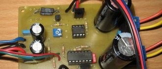
Stabilization equipment made with your own hands from available and inexpensive radio components may look something like this. The chassis and housing can be selected from old industrial equipment (for example, from an oscilloscope)
Types and technical characteristics of thyristor regulator
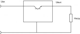
Due to the fact that the thyristor passes voltage of only one polarity through itself, it cannot be used to control a transformer without additional elements:
- Connect the thyristor to a diode bridge of 4 diodes at the “+” and “-“ terminals. The “~” pins are connected to the open circuit instead of the switch or in series with it. The diode bridge rectifies the voltage and the thyristor is supplied with power of only one polarity.
- Use two thyristors connected back-to-back and for control the control outputs are connected through a variable resistor. Each element opens at its own polarity, and both together control the voltage across the load.
The opening of the thyristor occurs when a current exceeds a certain value and there are two ways to control the opening angle:
- Variable resistance connected between the anode and the control electrode. During the first half of the half-wave, the voltage and control current increase and when it reaches a certain value, depending on the brand of the element. The disadvantage of this circuit is the limited adjustment range of 110-220V, but this is enough to control the charger transformer.
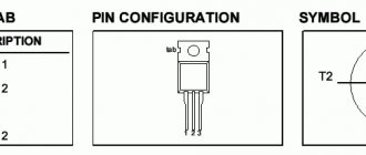
- Control of pulses that are supplied by a separate circuit to the control electrode at a certain moment of the half-wave of a sine wave. The permissible current and voltage of the thyristor regulator depend primarily on the installed thyristors. The most common are thyristors of the KU 202 series, but in some cases the use of other elements is allowed:
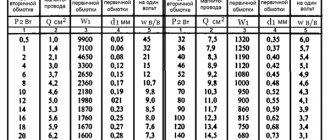
- KU 202N – 400V, 30A. Mounted on M6 thread. When adjusting the primary winding, the current of which is less than 1A, they are used without radiators.
- KU 201l - 300V, 30A, fastening - M6 thread. Can be used in the primary winding.
- KU 201a – 25V, 30A, fastening – M6 thread. Can only be used with radiators when adjusted after the transformer.
- KU 101g – 80V, 1A. Looks like a transistor. They are not used in power circuits of chargers, only in control circuits.
- KU 104a – 6B, 3A. Also not used in power circuits.
Schemes of simple powerful battery chargers.
Transformer chargers for car batteries with high efficiency: the simplest ones using quenching capacitors, as well as pulse ones using thyristors, triacs and powerful field-effect transistors.First, let's warm up and forget about such a parameter as efficiency. Let's assume that there is a strong desire to charge a car battery, but there is no possibility due to a complete lack of charging. Let’s also assume that the following are lost in the household: a 220-volt incandescent lamp, a diode bridge with a permissible current exceeding the current at which we will charge the battery, or, at worst, just a power (rectifier) diode with the same permissible current and maximum reverse voltage - not less than 300V.
Fig.1
Having soldered the circuit shown in Fig. 1 on the left, and being puzzled by the observance of safety precautions, as well as the polarity of connecting the charger to the battery, we get a completely functional device that provides a normalized and constant charging current for the battery under charge. Since 220 volts is the effective value of the alternating voltage of the network, the current flowing through the battery can be calculated using a simple formula: Icharge(A) = Plamp(W) / (220 - Uaccb)(V) ≈ Plamp(W) / 220( IN) . Parallel connection of two lamps doubles the charging current, three – triples, etc. to a reasonable infinity. The circuit shown in Fig. 1 on the right produces a current that is half that of the previous one. The great advantage of the above circuits is the ability to charge any batteries, regardless of their own voltage values.
Another simple and low-cost charger circuit for a battery with an operating voltage of 12 or 6 V and an electrical capacity of 10 to 120 A/h is shown in Fig. 2.
Fig.2
The device consists of a step-down transformer T1 and a powerful rectifier assembled using diodes VD2-VD5. The charging current is set by switches S2-S5, with the help of which quenching capacitors C1-C4 are connected to the power circuit of the primary winding of the transformer. Thanks to the multiple “weight” of each switch, various combinations allow you to stepwise adjust the charging current in the range of 1–15 A in 1 A increments. This is enough to select the optimal charging current.
The design can use any power transformer with a power of about 300 W, including homemade ones. It should produce a voltage of 22–24 V on the secondary winding at a current of up to 10–15 A. In place of VD2-VD5, any rectifier diodes that can withstand a forward current of at least 10 A and a reverse voltage of at least 40 V are suitable. D214 or D242 are suitable. They should be installed through insulating gaskets on a radiator with a dissipation area of at least 300 square meters. cm.
Capacitors C2-C5 must be non-polar paper with an operating voltage of at least 300 V. Suitable, for example, are MBChG, KBG-MN, MBGO, MBGP, MBM, MBGCh. Similar cube-shaped capacitors were widely used as phase-shifting capacitors for electric motors in household appliances. A DC voltmeter of type M5−2 with a measurement limit of 30 V was used as PU1. PA1 is an ammeter of the same type with a measurement limit of 30 A.
In this circuit, a high efficiency indicator is achieved through the use of capacitors as current-setting elements, which, as is known, have reactive conductivity and do not emit thermal power. Next we will present pulse (key) chargers built on a different principle, but also characterized by low inherent power consumption.
One of the first pulsed memory devices to appear on the market were thyristor devices. In general, a thyristor is a rather capricious device and requires compliance with a certain set of conditions for reliable operation. That is why most of the simplest circuits given in various sources suffer from not very stable operation and the need to select elements.
Among the successful simple developments, one can cite the circuit of a thyristor charger from the book of the respected T. Khodasevich “Chargers”, repeated many times by numerous amateur radio lads and depicted in Fig. 3.
Fig.3
Here's what the author writes:
The charger allows you to charge car batteries with a current of 0 to 10 A, and can also serve as an adjustable power source for a powerful low-voltage soldering iron, vulcanizer, or portable lamp. The charging current is similar in shape to pulse current, which is believed to help extend battery life. The device is operational at ambient temperatures from - 35 °C to + 35 °C.
The charger is a thyristor power regulator with phase-pulse control, powered from winding II of step-down transformer T1 through a diode bridge VDI...VD4. The thyristor control unit is made on an analogue of the unijunction transistor VTI, VT2. The time during which capacitor C2 charges before switching the unijunction transistor can be adjusted by variable resistor R1. When the engine is in the extreme right position according to the diagram, the charging current will be maximum, and vice versa. Diode VD5 protects the control circuit of thyristor VS1 from reverse voltage that occurs when the thyristor is turned on.
Capacitor C2 - K73-11, with a capacity of 0.47 to 1 μF, or K73-16, K73-17, K42U-2, MBGP. We will replace the KT361A transistor with KT361B - KT361Ё, KT3107L, KT502V, KT502G, KT501Zh - KT50IK, and KT315L with KT315B + KT315D KT312B, KT3102L, KT503V + KT503G, P307. Instead of KD105B, diodes KD105V, KD105G or D226 with any letter index are suitable. Variable resistor R1 - SP-1, SPZ-30a or SPO-1. Ammeter PA1 - any direct current with a 10 A scale. You can make it yourself from any milliammeter by selecting a shunt based on a standard ammeter. Fuse F1 is a fuse, but it is convenient to use a 10 A circuit breaker or a car bimetallic one for the same current. Diodes VD1... VP4 can be any for a forward current of 10 A and a reverse voltage of at least 50 V (series D242, D243, D245, KD203, KD210, KD213). The rectifier diodes and thyristor are installed on heat sinks, each with a useful area of about 100 cm*. To improve the thermal contact of devices with heat sinks, it is advisable to use thermally conductive pastes. Instead of the KU202V thyristor, KU202G - KU202E are suitable. It has been tested in practice that the device works normally with more powerful thyristors T-160, T-250. The device can use a ready-made network step-down transformer of the required power with a secondary winding voltage of 18 to 22 V. If the transformer has a voltage on the secondary winding of more than 18 V, resistor R5 should be replaced with another, higher resistance (for example, at 24 ... 26 V resistance the resistor should be increased to 200 Ohms).
Despite the popularity and operability of the above circuit, when the device operates, many note an uncharacteristic hum of the transformer at frequencies other than 100 Hz. This is due to the lack of clear and fast rises/falls in the signals arriving at the control input of the thyristor when it is turned on/off, which in turn creates conditions for generation processes to occur in the load.
Pulse chargers work somewhat better and more reliably, in which the switching element is made on a symmetrical (bipolar) analogue of a thyristor - a triac. Figure 4 shows a diagram of a similar device from the above-mentioned book by T. Khodasevich.
Fig.4
The simple charger described below has wide limits for regulating the charging current - practically from 0 to 10A and can be used to charge various 12V batteries. The device is based on a triac regulator with a low-power diode bridge VD1-VD4 and resistors R3 and R5. After connecting the device to the network, with its half-cycle positive, capacitor C2 begins to charge through resistor R3, diode VD1 and series-connected resistors R1 and R2. With a negative half-cycle - through the same R1 and R2, diode VD2 and resistor R5. In both cases, the capacitor is charged to the same voltage, only the polarity of its charging changes. As soon as the voltage on the capacitor reaches the ignition threshold of the neon lamp HL1, it lights up and the capacitor is quickly discharged through the lamp and the control electrode of the triac VS1. In this case, the triac opens. At the end of the half-cycle, the triac closes. the described process is repeated in each half-cycle of the network. It is well known that controlling a triac with a short pulse has the disadvantage that with an inductive or high-resistance active load, the anode current of the device may not have time to reach the holding current value during the action of the control pulse. One of the measures to eliminate this drawback is to connect a resistor in parallel with the load. In the described charger, such resistors are resistors R3 and R5, which, depending on the polarity of the half-cycle of the mains voltage, are alternately connected in parallel to the primary winding of the transformer. The powerful resistor R6, which is the load of the rectifier VD5, VD6, also serves the same purpose. The same resistor generates discharge current pulses, which extend the battery life.
Instead of resistor R6, you can install an incandescent lamp with a voltage of 12V and a power of 10W. During the manufacture of the transformer, the following parameters are specified: voltage on the secondary winding 20V at a current of 10A.
The device described above can be somewhat simplified by using a dinistor in its high-voltage part (Fig. 5). Fig.5
We reviewed this diagram with diagrams in detail on the page link to the page. Therefore, I will not repeat myself, I will only say that the presence of a snubber circuit, shown in blue in the diagram, is mandatory. The primary winding of the network transformer acts as the load.
In modern chargers, powerful field-effect transistors are almost universally used as a switching (regulating) element. One of these devices was described in detail in the magazine Radio No. 5 2011 on page 44.
Fig.6
The charger control unit is a pulse generator assembled on elements DD1.1 and DD1.2 (see diagram in Fig. 6) and allows you to regulate the duty cycle of pulses, a buffer amplifier - an inverter on elements DD1.3 and DD1.4 and a switching regulator element - field-effect transistor VT1. With the element ratings indicated in the diagram, the generator frequency is about 13 kHz. Since the resistance of the open channel of transistor VT1 is very small (0.017 0m) and it operates in switching mode, with a charging current of up to 5 A, the transistor practically does not heat up - the dissipated thermal power does not exceed 0.55 W. As a step-down, a network transformer with an overall power of 150 W with a secondary winding was used, providing a constant voltage of 16 ... 17 V on capacitor C1 and a charging current of up to 6 A. The rectifier bridge is assembled on Schottky diodes, VD1 is a dual SBL4045PT, and VD2 and VD3 are single 10TQ045 . If the secondary winding of a network transformer is wound with a tap from the middle, the number of diodes in the rectifier and the heat generation from them can be halved. The board drawing is shown in Fig. 7.
Fig.7
The described control unit can also be used in lighting and heating devices to change the rotation speed of commutator electric motors. In this case, the supply voltage of the devices can be varied within wide limits, determined by the maximum permissible parameters for the switching transistor and, of course, the rectifier. In particular, the IRFZ46N transistor used in the node has a maximum power dissipation of 107 W, a maximum current through the channel of 53 A, and a maximum drain-source voltage of 55 V. It can be replaced with an IRFZ44N transistor. The proposed device allows you to regulate the power from zero to the maximum value, and the control transistor does not need to effectively remove heat when the load current increases to 5 A.
As a result of prolonged or improper use of car batteries, their plates can become sulfated, which leads to their degradation and subsequent failure. There is a known method for restoring such batteries by charging them with an “asymmetrical” current. In this case, the ratio of charging and discharging current is selected to be 10:1 (optimal mode). This mode allows you not only to restore sulfated batteries, but also to carry out preventive treatment of serviceable ones.
Fig.8
Figure 8 shows a simple charger designed to use the method described above. The circuit provides a pulse charging current of up to 10 A (used for accelerated charging). To restore and train batteries, it is better to set the pulse charging current to 5 A. In this case, the discharge current will be 0.5 A. The discharge current is determined by the value of the resistor R4. The circuit is designed in such a way that the battery is charged by current pulses during one half of the period of the mains voltage, when the voltage at the output of the circuit exceeds the voltage at the battery. During the second half-cycle, diodes VD1, VD2 are closed and the battery is discharged through load resistance R4. The charging current value is set by regulator R2 using an ammeter. Considering that when charging the battery, part of the current also flows through resistor R4 (10%), the readings of ammeter PA1 should correspond to 1.8 A (for a pulse charging current of 5 A), since the ammeter shows the average value of the current over a period of time, and the charge produced during half the period. The circuit provides protection for the battery from uncontrolled discharge in the event of an accidental loss of mains voltage. In this case, relay K1 with its contacts will open the battery connection circuit. Relay K1 is used of the RPU-0 type with an operating winding voltage of 24 V or a lower voltage, but in this case a limiting resistor is connected in series with the winding.
For the device, you can use a transformer with a power of at least 150 W with a voltage in the secondary winding of 22...25 V. The PA1 measuring device is suitable with a scale of 0...5 A (0...3 A), for example M42100. Transistor VT1 is installed on a radiator with an area of at least 200 square meters. cm, for which it is convenient to use the metal case of the charger design.
What is a triac
The thyristor has a drawback that complicates its use in an alternating current network - it passes through only one half-wave and the output produces a constant pulsating voltage instead of an alternating voltage. Therefore, these devices are used in pairs or together with a diode bridge. The triac is free from this drawback.
A triac is similar in appearance to a thyristor. Just like a thyristor, it opens with a current pulse flowing through the control electrode, but this device passes both half-waves through itself and is capable of operating in an alternating current network.
Schematic diagram of a triac current regulator for active and inductive loads. The design of a triac regulator is similar to a thyristor regulator. The difference is that the triac controls both polarities and therefore there is no need to use a diode bridge or back-to-back connection of elements.
In addition, the polarity of the control voltage does not matter for the triac, which simplifies the pulse control circuit.
Advice! To adjust the triac, you can use a dimmer from an incandescent lamp. To do this, it is connected between the anode and the control electrode of the power triac.
Switching power supply
The operation of the UPS is based on double voltage conversion. First, the input signal is converted into DC voltage and then into high frequency pulses. The transformer used in the circuit does not require large dimensions. When the transformer and transistor are switched on together in switch mode, a blocking generator is formed. The change and stabilization of the output signal occurs by decreasing the duration of the open state of the transistor, which is controlled by a specialized microcircuit. Its operation is based on the principle of pulse width modulation (PWM). The advantage of this type of power supply:
- light weight;
- low cost;
- Efficiency reaches 98%;
- protection against short circuit and overload.
Disadvantages include the complexity of the circuitry and the fact that such a power source introduces high-frequency interference into the power line .
UPS operating principle
The mains voltage enters the circuit through a fuse, then to a capacitive noise filter. Next, onto the rectifier block of diodes. A smoothing electrolytic capacitance is connected to the output of the rectifier. The voltage across the capacitor is reduced, through a chain of resistors and a zener diode, to provide the starting value of the microcircuit. The microcircuit controls the operation of the key transistor through a limiting resistor.
When a rectangular pulse arrives at the transistor, it opens, and current begins to flow through the winding of the pulse transformer. As a result, an EMF is induced and voltage appears on the secondary winding. If the duration of the pulse arriving at the key transistor increases, then the magnitude of the output signal also increases; if it decreases, it decreases accordingly.
Feedback is used to obtain a stable signal . It is assembled using an optocoupler and a resistor. As the signal value on the secondary winding of the transformer increases, the current flowing through the optocoupler also increases, which leads to a decrease in the resistance of the phototransistor of the optocoupler. As a result, the voltage drop across the resistor increases and decreases at the input of the PWM controller. The pulse duration sent by the microcircuit to the transistor switch increases.
Other simple options for adjusting the voltage in the primary
In addition to thyristor and triac regulators, there are other ways to control the charging current in the primary winding of a transformer:
- Switching the leads of the primary winding. The disadvantage is that these conclusions must be made when winding the coils.
- By connecting the charger after LATRA (laboratory autotransformer). Its power must be at least 160W.
- Variable resistance connected in series with the transformer. Its parameters are approximately 50-100 Ohm, power 50 W and depend on the specific charger.
Despite the advent of modern chargers, many car owners have devices with conventional transformers, and adjusting the device along the primary winding makes it possible to do without powerful thyristors or additional resistances.