Last time we talked about the basics of selective defenses.
Today I will give an example of constructing a selectivity map for a 0.4-10 kV network. This topic intersects with our Course on the protection of 10/0.4 kV transformers and we will get ahead a little by building a protection characteristic for such a transformer.
By the way, if you are interested in a professional program for constructing a selectivity map with advanced functionality and databases, then check out this article. For now we will make do with the basic version of this program
As an example, we will specifically take different types of protective devices (old electromechanical direct action relays, microprocessor terminals and a 0.4 kV automatic machine) in order to test all the capabilities of the Greedis-KS program.
This set of protective devices is most typical for Russian distribution networks, when new facilities are connected to old substations. Go!
There are several ways to construct a selectivity map:
- Manually by points, using a standard graphic editor (AutoCAD, Visio, Compass)
This method is very labor-intensive and inconvenient, but it allows you to display all the necessary information
- Using MS Excel (or MathCad), specifying the characteristic in the form of a data table (current-time).
This is a normal method, many people use it, but problems arise with the construction of some elements, for example, vertical marks to indicate short-circuit currents.
- Using specialized programs.
This is what we are using today, having built a selectivity map using the Greedis-KS program.
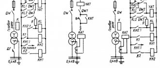
The network diagram is shown in Fig. 1. Suppose we have calculated the protection of a 10/0.4 kV transformer and want to ensure its selectivity with adjacent relay protections, i.e. protection of the 10 kV cable from the RTP and the 0.4 kV input switch.
Rice. 1
Before constructing a selectivity map, you must determine the settings of adjacent protections. Some protections you calculate, others you receive as input data.
List of protective devices:
- On the line extending from the distribution point, protection is installed using a direct-acting relay RTV-II.
- Protection of the 10/0.4 kV transformer is carried out by the microprocessor relay protection unit BMRZ-152-KL.
- On the 0.4 kV side, a Masterpact input switch with a Micrologic 5.0 digital protection unit is installed.
The device settings are shown in Fig. 1, at the bottom.
Types of selectivity of protective devices
Automatic protection devices are classified according to the PUE in accordance with the connection diagrams:
- With a complete circuit, several devices are connected in series. In the event of an accident, the device that is located at the minimum distance from the fault will operate the fastest. This is the main condition for the operation of protective systems.
- The partial selective protection circuit operates similarly to the previous option, with the exception of some restrictions set on the magnitude of the current.
- Timing schemes are distinguished by selectivity, that is, different holding times for devices with the same parameters. Thus, not only selective protection is provided, but also insurance of circuit breakers in terms of shutdown speed in case of their malfunction. For example, the first device should operate in 0.2 seconds. If it turns out to be faulty, then after 0.4 seconds the second device will work.
- Current selectivity has the same principle of operation as time selectivity, but in this case the main criterion is the maximum value of the current mark. Current values are set in the direction from the power source to the loads in descending order.
- The most complex feature of the device is considered to be time-current selectivity. For such circuits, equipment of four groups is used - A, B, C and D. Each of them has its own reaction to electric current and ensures shutdown at the right time. The protection circuit against short circuits is designed taking into account the individual characteristics of each of them. If necessary, selectivity is ensured between the fuses and the circuit breaker.
- Zone schemes are most often used at industrial production facilities. This method of selectivity is considered not only complex, but also an expensive option that requires special tracking devices. At the same time, all received data is concentrated in the control center, which determines which machine will be used to disconnect. That is, it instantly performs the necessary calculation. Such devices use electronic releases that operate according to the following scheme, provided for by the PUE: in the event of an emergency, the lower-level device sends a signal to the higher-level one. If after 1 second the lower machine does not operate, the second device will immediately turn on.
- The energy scheme assumes the rapid action of selectivity of circuit breakers, in which short-circuit currents do not have time to reach their maximum value.
How to build a selectivity map?
Protective devices are installed sequentially in the network and each has its own characteristics. If we take any protection and consider the circuit in relation to it, then the protections located next to the one under consideration will be called adjacent.
Translating the requirement for selectivity of relay protections into the language of characteristics, we get:
The time-current characteristics of adjacent protections should not intersect and between them there should always be a reserve along the time axis, which is called the selectivity stage
. How to make sure that the protections are selective among themselves?
It is necessary, according to the calculated settings, to plot all the characteristics of adjacent protections on one graph and analyze the graph for intersections of protective characteristics. If there are no intersections and there is always a gap between the curves along the time axis equal to 0.25-0.3 s (selectivity level for modern protections), then the protections are selective among themselves.
This graph is called a selectivity map
It is worth noting that the current cutoffs of adjacent protections on the graph may intersect because their selectivity is ensured by a special choice of operation current (current selectivity).
The characteristics of overload protection and overcurrent protection of adjacent protections should not overlap since their selectivity is ensured by different response time delays (time selectivity)
The analysis of the selectivity map is carried out visually, or, if the construction is carried out in a program, automatically.
Zone selectivity
Theory
The zone type of selectivity is carried out between two devices connected by a special information cable. This type of selectivity is based on the interaction of circuit breakers with each other through this cable. Circuit breakers of the same level are combined into so-called “zones”. If any of the circuit breakers in a given zone detect a fault, it sends a blocking signal to the upstream protection device. The latter, in turn, begins counting the additional time delay. If during this time the device located below is not able to switch off, then switching is carried out by the switch located above. If a breaker from any zone detects a short circuit and does not receive a blocking signal, it will operate without additional time delay in accordance with the standard settings.
An example of a zone topology is shown in Figure 5.
Rice. 5. Topology for constructing zones and connecting devices for zone selectivity.
Zone selectivity can be implemented between air circuit breakers and molded case circuit breakers equipped with sophisticated microprocessor-based circuit breakers with digital signal processing technology.
Case Study
Let's consider the implementation of zone selectivity between two ABB molded case circuit breakers of the Tmax T4L series with an electronic release PR223EF. To ensure zone selectivity between two (or more) circuit breakers equipped with PR223EF releases, it is necessary to implement a connection via a serial connection (IL bus).
Based on the technical data provided by the manufacturer, the selectivity current limit can be determined. For this example, this value can reach 100 kA.
Whatever method of coordination of protective devices is provided, when designing electrical networks of large enterprises, so-called selectivity maps are necessarily drawn up. They indicate all the trip settings of all protection devices, starting from circuit breakers installed in the substation and ending with devices in distribution boards. Modern software helps to facilitate the process of selecting and coordinating equipment, as well as drawing up such maps. For example, ABB Curves software allows you to create a diagram, build time-current characteristics of circuit breakers, check the coordination of devices, and also build selectivity maps taking into account the necessary settings of the releases
The latter need to be given special attention, since without proper settings, even correctly selected circuit breakers may end up being uncoordinated with each other
Designing a modern selective plant at an enterprise is a complex and time-consuming task, the implementation of which must be approached responsibly: the slightest mistake can lead to accidents that entail serious consequences for equipment and personnel. That is why selectivity must be ensured in different ways and at different levels, especially since modern protection devices help to implement various principles of coordination.
1. The short circuit zone refers to the range of current values and, therefore, the corresponding part of the circuit breaker response curves, which are 8-10 times higher than the rated current.
Selectivity principle
When designing circuits at sites with various electrical equipment, issues that ensure the safe operation of electrical installations must be taken into account. All installed protection elements have certain technical characteristics and are not universal for various emergency situations.
Selectivity is translated into Russian as selectivity; correctly selected technical characteristics of protection elements for a specific section of the circuit ensure reliable, trouble-free operation. The electrical circuit at any facility is divided into sections where circuit breakers of a certain category are installed, with the corresponding characteristics.
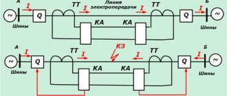
To illustrate the operation of selective protection circuits, let’s consider circuits where current passes from the power source directly to the consumer (load). In this case, malfunction, short circuit, current leakage through the insulating layer and other reasons may occur in different places:
- On individual elements of load equipment;
- In power supply wiring in different sections along the entire length;
- In distribution boards, transformer substations;
- On a generator that produces electric current.
For each listed location where a malfunction occurs, in order to promptly turn off electrical equipment and prevent burnout of individual elements, it is necessary to install circuit breakers with the appropriate characteristics. For effective operation, all protection elements must be coordinated with each other.
Selectivity map of three-stage time-current protection
The diagram shows time in seconds along the vertical axis, and the load current value along the horizontal axis. Green dots indicate the characteristic values that the protective circuit breakers must comply with at each stage.
Selectivity for the electrical network of an individual object can be divided into two types:
- Absolute - when a specific section of the circuit with equipment elements where the malfunction occurs is switched off;
- Relative - with this type of electoral system, a shutdown can occur in several directions of the network with different equipment, regardless of which section the fault occurred. This is especially true in circuits with powerful electric motors, where inrush currents are high.
To eliminate false positives, additional options are installed:
- For each load element, the protection has a time delay to turn off;
- The magnitude of the operating current is set;
- Voltage value;
- Temperature;
- Frequency, resistance and other parameters, depending on the network parameters and type of load equipment.
Comparison of NSAIDs
Some NSAIDs have quite serious side effects, while others do not. This is due to the peculiarities of the mechanism of action: how drugs affect certain types of COX - COX 1, COX 2, COX 3.
In healthy people, COX 1 is found in almost all tissues and organs (for example, in the kidneys and gastrointestinal tract), where it performs its most important function. With the help of COX-synthesized prostaglandins, the integrity of the intestinal and gastric mucosa and adequate blood flow in it are maintained, the secretion of hydrochloric acid is reduced, the pH is increased, the secretion of mucus and phospholipids is ensured, and cell proliferation (reproduction) is stimulated.
NSAID drugs that inhibit COX 1 help reduce the concentration of prostaglandins not only in the inflammatory focus, but throughout the human body, resulting in the development of negative consequences.
In healthy tissues, COX 2 is usually found in small quantities or is completely absent. An increase in its level is observed directly during inflammation or in the inflammatory focus itself. NSAID drugs that selectively inhibit COX 2 are most often taken systemically, but their action is directed specifically at the site of inflammation, helping to reduce the inflammatory process there.
Despite its contribution to the development of fever and pain, COX 3 does not participate in inflammatory processes. The action of certain NSAIDs is aimed at this type of enzyme, but at the same time they have a weak effect on COX 1 and COX 2. According to some experts, COX 3 is not an independent isoform of the enzyme, but is a variant of COX 1, but this statement is not currently true confirmed by additional studies.
Main tasks of selective protection
As for a person, his perception of the world around him, the choice of information, as well as its memorization are selective.
What is selectivity in electrical engineering, and why is it needed?
The tasks of electrical selective protection include:
- guaranteeing the safety of equipment and operating personnel;
- instantly identifying the location of the fault and disconnecting only the faulty section;
- reducing the negative effects of the accident on other components and parts of electrical appliances;
- minimizing damage to the faulty area;
- guaranteeing maximum continuity of operation of the electrical system;
- achieving ease of operation of electrical equipment.
Types of selective protection
Full and partial
Full protection is designed for serial connection of devices. In the event of an accident, the protective unit that is closest to the site of the breakdown will operate as quickly as possible. Partial selective protection is in many ways similar to full, but operates only up to a certain current value.
Temporal and time-current
Time selectivity is when series-connected devices with identical current characteristics have a different time delay for operation (with a sequential increase from the problem area to the power source). Temporary protection is used so that the machines can insure each other in the event of a failure. For example, the first one should work in 0.1 seconds; if it is faulty, after 0.5 seconds the second one comes into play, and if necessary, the third one will work in 1 second.
Time-current selectivity is considered to be as complex as possible. It uses equipment of 4 groups - A, B, C and D. Each of them has a personal reaction to electric current and shuts down at the required moment. The best protection is achieved in group A, which is mainly used for electrical circuits. The most popular type of units is C, however, experts do not advise installing them everywhere and thoughtlessly.
Current selectivity
This type is similar in its method of operation to the temporary one, but the difference is that the main criterion is the maximum value of the current mark. The current values are arranged in descending order from the power source to the load objects.
If a short circuit occurs near switch A, the protection of end B should not operate, and the switch itself must remove voltage from the device. For current selectivity to guarantee total selectivity, there will need to be a large resistance between both switches. It is obtained using:
- long power transmission line;
- transformer winding inserts;
- inclusion of a wire of a smaller cross-section into the gap.
Watch this video on YouTube
Energy
This scheme implies the speed of selectivity of auto switches. In this case, short circuit currents (SC) do not have the opportunity to reach their maximum values.
These “rapid-fire” machines operate within literally a couple of milliseconds. Due to the high dynamics of the loads, it is extremely difficult to coordinate the actual time-current parameters of the protections.
The average user is not able to track the characteristics of this type of selectivity. The manufacturer is obliged to provide them in the form of graphs and tables.
Zone selectivity
Such schemes are often used in industrial facilities. This is not only a very complex, but also an extremely expensive method of protection. To use zone selectivity, you need to purchase special tracking devices.
All data obtained during the operation of the devices is concentrated in the control center. It determines which machine needs to be activated to turn it off.
These devices use electronic releases. Their operating scheme is as follows: when an emergency occurs, the lower-level device sends a signal to the one above. If after 1 second the lower device does not work, the second one takes over.
Principle of logic
The principle of logic in a radial network
The given Picture 9 explains the principle of operation of the logic. Each of the 4 digital relays uses a current setting equal to the most recent sensitive stage. This stage has an operating time of 0.2 s. Logical selectivity implies the possibility of blocking the relay with a LO (logical standby) signal. This signal is supplied through the channel from the previous protection relay. Each of the relays can transmit such signals in transit.
As can be seen from the figure, during a short circuit at point K1, all other relays, from the LO signal supplied by relay K1, will be on hold. Relay K1 will operate and shut down. In the event of a short circuit at point 2, relay K4 will operate in the same way.
Principle of logic
To implement circuits using this principle, digital relays are needed. The relays are connected to each other by a twisted pair line, a fiber optic cable, or via a telephone line (using a modem). With the help of such lines, information is received (transmitted) to the dispatch console from different objects and between the relays themselves.
The principle of logic in a radial network
The given Picture 9 explains the principle of operation of the logic. Each of the 4 digital relays uses a current setting equal to the most recent sensitive stage. This stage has an operating time of 0.2 s. Logical selectivity implies the possibility of blocking the relay with a LO (logical standby) signal. This signal is supplied through the channel from the previous protection relay. Each of the relays can transmit such signals in transit.
As can be seen from the figure, during a short circuit at point K1, all other relays, from the LO signal supplied by relay K1, will be on hold. Relay K1 will operate and shut down. In the event of a short circuit at point 2, relay K4 will operate in the same way.
Such schemes for constructing logical control are demanding on the reliability of communication lines between elements.
Current selectivity
This type of selective protection is installed in each electrical circuit at its beginning. If a short circuit occurs in an electrical network consisting of these circuits, the current increases according to its impedance. In this case, the inductance limits the rate of current rise and there is a certain minimum value. This value is the protection threshold.
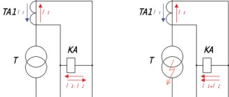
At the same time, protective devices can operate at slightly lower current values, if necessary. But the magnitude of the triggering current must be in the range of current values, which will be greater than in the case of a short circuit outside the protection coverage area. An example of current protection for a circuit with a transformer connected between cable power lines is shown in the image below:
The advantage of current selectivity is the ability to respond only to faults within the protected area and in connection with the consumer, excluding accidents outside the protected area. It is characterized by fast response, low cost and circuit simplicity. This is its advantage. The disadvantage is the difficulty of adjusting the selectivity of sequentially installed protection devices when they are located in neighboring areas due to the similarity of process parameters determined by emergency situations.
We plot the protective characteristics corresponding to the received settings.
2.1 Relay RTV-II
We take the relay characteristics from the reference data.
The relay response setting is 375 A. This is the beginning of our characteristics.
The protection characteristic switches to the independent part at 160% of the operating current, i.e. at 600 A. The independent characteristic has a time delay of 1.5 s. Let's construct the resulting dependence.
The characteristics of the RTV-II relay are not yet available in the Gridis-KS database, so we will use the built-in tool for constructing an arbitrary dependence.
We will transfer the coordinates of the calculated points to a txt file as shown in the figure below and load the file into the program.
Main functions
The key objectives of selective protection are to ensure uninterrupted functioning of the electrical system and prevent mechanisms from burning out when threats arise. The only condition for the correct operation of this type of protection is the consistency of the protective units with each other.
As soon as an emergency occurs, the damaged area is instantly identified and switched off using selective protection. At the same time, the working places continue to work, and the disabled ones do not interfere with them in any way. Selectivity significantly reduces the load on electrical installations.
The basic principle of arranging this type of protection lies in the equipment of circuit breakers with a rated current that is less than that of the device at the input. In total, they can exceed the nominal value of the group machine, but individually - never. For example, when installing a 50 A input device, the next device should not have a rating higher than 40 A. The unit located as close as possible to the emergency site will always operate first.
Thus, the main functions of selective protection include:
- ensuring the safety of electrical devices and workers;
- quick identification and shutdown of the area of the electrical system where the breakdown occurred (at the same time, the working areas do not stop functioning);
- reduction of negative consequences for the working parts of electrical mechanisms;
- reducing the load on component mechanisms, preventing breakdowns in the faulty area;
- guarantee of continuous work process and constant high-level power supply.
- support for optimal operation of a particular installation.
What is selectivity of protection?
As already mentioned, selectivity is understood as a feature of relay protection. It is determined by the ability to look for a faulty element in the entire electrical network and turn off the emergency section, and not the entire system.
Selective protection can be absolute or relative.
- Absolute protection involves precise operation of fuses in the section of the network where a short circuit or breakdown occurred.
- Relative selectivity causes the circuit breakers that are also located near the breakdown site to be turned off if the protection in those areas does not work.
Main functions
The key objectives of selective protection are to ensure the uninterrupted functioning of the electrical system and prevent mechanisms from burning out when threats arise. The only condition for the correct operation of this type of protection is the consistency of the protective units with each other.
As soon as an emergency occurs, the damaged area is instantly identified and switched off using selective protection. At the same time, the working places continue to work, and the disabled ones do not interfere with them in any way. Selectivity significantly reduces the load on electrical installations.
The basic principle of arranging this type of protection lies in the equipment of circuit breakers with a rated current that is less than that of the device at the input. In total, they can exceed the nominal value of the group machine, but individually - never. For example, when installing a 50 A input device, the next device should not have a rating higher than 40 A. The unit located as close as possible to the emergency site will always operate first.
NOTE! The choice of circuit breakers, including those for protection with absolute selectivity, depends on their rating and response characteristics, which are designated B, C and D. Often, various types of circuit breakers, fuses, and RCDs serve as devices that protect the electrical system.
Thus, the main functions of selective protection include:
- ensuring the safety of electrical devices and workers;
- quick identification and shutdown of the area of the electrical system where the breakdown occurred (at the same time, the working areas do not stop functioning);
- reduction of negative consequences for the working parts of electrical mechanisms;
- reducing the load on component mechanisms, preventing breakdowns in the faulty area;
- guarantee of continuous work process and constant high-level power supply.
- support for optimal operation of a particular installation.
Design of networks up to 1000V.
Intrashop electrical networks with voltages up to 1 kV differ from each other in many design features. Network designs depend on the conductor material, insulation methods, environmental conditions, the degree of responsibility of the electrical installation, the distance of the power source to the consumer, the nature of the load (quiet, shock) and other factors.
Based on the methods of insulation, networks with voltages up to 1 kV can be divided into two large groups: those made from busbars and non-insulated conductors and cables. Networks with voltages up to 1 kV, carried out with bare wires, include overhead lines, which have extremely limited use in industrial enterprises. Busbar trunking is made from non-insulated and insulated busbars. Electrical wiring and cable lines refer to networks made of insulated conductors.
Household devices
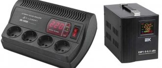
The feasibility of purchasing a reverse power generator for your home remains highly questionable. Manufacturers of such devices simply cannot know what equipment you have at home, when and how long a vacuum cleaner or fan works, what power your refrigerator has, and how many electronics with capacitors and power supplies are in your house. Typically, such devices are calculated, as they say, “by eye” and there can be no talk of 5% savings. The maximum that can be achieved is 0.5 or at most 1%. Considering the price of devices sold on the Internet, with such efficiency, their return on investment is almost zero. So is it worth it?
It is much more effective to apply this principle individually and, based on measurements of the deflection angle, select the required capacity for each more or less powerful equipment with an electric motor.
The concept of selectivity. Methods for ensuring selectivity
The selection of an electrical installation protection system is an important aspect both to ensure the economical and technically correct operation of the entire installation and to minimize the consequences caused by abnormal operating conditions or ongoing faults.
This article examines the coordination of various devices intended to protect parts of an installation or specific components, with the aim of:
- ensuring the safety of the installation and personnel in all cases;
- quickly identifying and shutting down the zone in which a problem situation has arisen, without carrying out general shutdowns that stop the supply of electricity to areas of normal operation of the installation;
- reducing the load on elements and preventing damage in the fault zone;
- ensuring continuity of power supply of adequate quality;
- providing personnel responsible for system maintenance and management with the information they need to quickly restore service to the rest of the power grid with minimal disruption;
- achieving optimal coordination of factors of reliability, ease of operation and economic efficiency.
General concept of selectivity
As already mentioned, selectivity is understood as a feature of relay protection. It is determined by the ability to look for a faulty element in the entire electrical network and turn off the emergency section, and not the entire system.
Selective protection can be absolute or relative.
- Absolute protection involves precise operation of fuses in the section of the network where a short circuit or breakdown occurred.
- Relative selectivity causes the circuit breakers that are also located near the breakdown site to be turned off if the protection in those areas does not work.
Types of selective connection schemes
Protective equipment is divided into several types based on selectivity. These include the following types of protection:
- full;
- partial;
- current;
- temporary;
- time-current;
- energy.
Each of them needs to be discussed separately.
With such circuit protection, the devices are connected in series. In the event of an overcurrent, the circuit breaker that is closest to the fault will operate.
Important! Partial selective protection differs from full selectivity in that it operates only up to the set overcurrent value. By arranging the magnitudes of currents from the source to the load in descending order, they ensure the operation of current selectivity
The main measure here is the limiting value of the current tag
By arranging the magnitudes of currents from source to load in descending order, current selectivity is ensured. The main measure here is the limiting value of the current tag.
For example, starting from the power source or input, circuit breakers are installed in the sequence: 25A, 16A, 10A. All machines can have the same response time.
Important! There must be a high circuit resistance between the machines. Then they will have effective selectivity
They increase resistance by increasing the length of the line, including sections with a wire of smaller diameter or inserting a transformer winding.
Current selectivity
Temporal selectivity
Time-current selectivity is considered very difficult. To organize it, you need to select devices from groups: A, B, C, D. Group A has the highest protection (used in electrical circuits). Each of these groups has an individual response to the magnitude of the electric current and the time delay.
This protection is due to the properties of the switches provided by the manufacturer. Fast response - before short-circuit currents reach their maximum. Milliseconds count; it is very difficult to coordinate such selectivity.
Energy selectivity
Information. To provide such protection, additional power is required. The signal from each switch is sent to the control center. Shutdowns are made by electronic releases.
It is most rational to use such circuits in industrial enterprises, where systems have high values of short-circuit currents and significant operating currents.
Example and graph of zone selectivity
Functions and tasks of selectivity
The main task of selective protection is to ensure stable operation and safe operation of electrical installations. In the event of an emergency, the damaged area is identified almost instantly and is immediately switched off without disrupting the operation of healthy areas. Due to selectivity, the load on electrical installations is significantly reduced, and the negative consequences of a short circuit are reduced.
The precise and coordinated operation of automatic protective devices maximally meets the requirements for uninterrupted power supply. As a result, the selectivity of the circuit breaker maintains the continuity of all technological processes involving electrical installations. Disabled areas do not in any way affect their stable operation.
The basic rule of selective protection devices involves installing circuit breakers with a rated current lower than that of the input device. In total, they can exceed the rating of a group machine, but individually each of them must be at least one step lower. That is, when installing a 50 A input device, the next device on the line will have a rating of no higher than 40 A. The machine closest to the fault location is always triggered first.
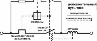
The selectivity of the machines is ensured by their design. Turning the power on and off is done using a special lever. Fixed contacts are connected to terminals, to which, in turn, conductors are connected. Quick opening is carried out using a moving contact connected to a spring. Disconnection is ensured by a bimetallic plate, which bends after heating if the current exceeds its maximum permissible value.
There is an adjusting screw to adjust the operating currents. Together, all elements contribute to quickly identifying the faulty area and cutting it off from the working parts.
The basic principle of selectivity is considered to be the sequential operation of protective equipment. In case of deviations from the norms, overheating will occur not only of the machines, but also of the electrical wiring. As a result, emergency situations arise with serious negative consequences.
When is a selectivity map needed?
Typically, a selectivity map is built for maximum current protection , namely for overload protection, overcurrent protection and current cut-off (TO).
Despite the fact that distance protections are also protections with relative selectivity, a selectivity map is not usually built for them. This is due to the fact that the selectivity of these protections is quite simple to analyze by calculation.
Overcurrent protection is used mainly for connections with voltage class up to 110 kV inclusive.
Thus, we find that the selectivity map should be built for protecting networks of 0.4-110 kV, namely:
- All network protection 0.4 kV (selectivity of circuit breakers and fuse links)
- All protection of 6-10 kV networks (except for differential protection of generators and motors)
- Most of the 35 kV networks (where there are no distance protections)
- Backup protection of step-down transformers with a higher voltage of 110 kV (last element of the selectivity map)
Today, in many projects, especially at 0.4 kV, there is no selectivity map. This is a violation of design standards, leading to non-selective outages of consumers.
Always build a protection selectivity map to avoid such cases!
Rules for drawing up a selectivity map
Maximum use of the protective properties of circuit breakers is ensured by drawing up a special map showing the selectivity of the electrical network protection, with a graphic designation of all possible processes. It is carried out in the form of an established diagram, which indicates all the current characteristics of the protective devices included in a specific electrical network.
When drawing up a map, certain rules must be followed:
- All electrical installations must be connected to a common power source.
- All locations of significant design points must be clearly visible, so the selectivity map is performed at the most appropriate scale.
- The diagram shows the protective properties of each machine, as well as the characteristics of possible short circuits at various points with their minimum and maximum values.
- The characteristics of the machines are plotted sequentially, in accordance with the order in which they are connected. To correctly construct a diagram, axes with main indicators are used. Based on the diagram, a special table is compiled to facilitate the selection of protective devices.
A correctly compiled map displays a complete picture of the settings of the machines that are consistent with each other. This makes it possible to compare the parameters of protective devices and the overall selectivity of protection. The map itself is primarily built on the basis of the axes of time-current characteristics and their varieties. As a rule, this one diagram displays the parameters of two or three machines. The horizontal x-axis contains current values (in kW), and the vertical ordinate indicates time (s).
A special program that can be easily found on the Internet helps speed up the compilation of a map. Sometimes such diagrams are not included in the design documentation for electrical equipment. This can lead to violations of established standards and power outages for consumers.
Protection selectivity map
There are no ideal nutrition options. Different load conditions imply different emergency situations. It is the selectivity map that allows you to see the operation of relay protection virtually. By simulating the design on paper, engineers can ensure that the protection can operate correctly in all modes. Branched circuits are characterized by the presence of protective devices with different time-current characteristics. For example, let’s take any machine gun and define it as “our defense.”
We will call the remaining devices in the diagram adjacent. The main principle of proper organization is that the time-current characteristics of all devices should not intersect at the same linear level. If we draw a time line as a coordinate axis, then there should be a gap between the stages of selectivity. This can only be seen on charts. This is a selectivity map: it combines the characteristics of adjacent protections.
Information: For simple schemes for organizing selective protection, mapping is not required. If there are no adjacent levels, compatibility is not calculated.
To construct maps, it is better to use special computer programs. Although professional engineers easily draw graphs with a pencil. After building all the parametric curves, the graph is checked for their intersection. If such a situation arises, the criticality is checked: perhaps nothing needs to be changed. If the power lines are not dependent on each other, dividing does not change anything.
In other cases, it is necessary to ensure a time difference along the time axis of at least 0.25 seconds.
In addition, even if the response time selectivities intersect, dilution can be organized based on the difference in the cutoff current. As a rule, both methods are used; this can be taken into account when constructing a map, or it can be left at a practical level.
Graphical representation of selectivity
For reliable current protection of electrical wiring, a selectivity card is required. It represents a diagram of the time-current characteristics of devices installed alternately in the circuit. The scale is chosen so that the protective properties of the devices are visible at the boundary points. In practice, selectivity maps are mostly not used in projects, which is a big drawback and leads to power outages for users.
The nominal ratio must be at least 2.5 to ensure selectivity. But even they have common response zones, albeit small ones. Only with a ratio of 3.2 is their intersection not observed. But in this case, one of the ratings may turn out to be too high and you will have to install wiring of a larger cross-section after the machine.
In most cases, selectivity of protection is not required. It is needed only where serious consequences may arise.
If the calculation results in overestimated values of the machine's ratings, switches or load switches are installed at the input.
You can also use special selective automatic machines.
All about the protection and automation of electrical networks
Last time we talked about the basics of selective defenses.
Today I will give an example of constructing a selectivity map for a 0.4-10 kV network. This topic intersects with our Course on the protection of 10/0.4 kV transformers and we will get ahead a little by building a protection characteristic for such a transformer.
By the way, if you are interested in a professional program for constructing a selectivity map with advanced functionality and databases, then check out this article. For now we will make do with the basic version of this program
Selectivity map
All characteristics of current devices are entered into a specific circuit. It allows you to create maximum protection for machines. Its main principle is the sequence of connecting devices.
When creating a map, certain rules are taken into account:
- one voltage source for all installations;
- the correct scale is needed for a good view of the calculated points;
- The minimum and maximum short circuit performance and protective properties are noted.
The absence of a well-constructed map leads to power supply disruptions. A visual diagram allows you to see the consistency of the settings and compare the operation of the machines. The diagram itself consists of two axes:
- The abscissa axis is the current value in kV;
- The y-axis is time in seconds.
We bring the settings to one voltage.
We calculated the protection of a 10/0.4 kV transformer, so we bring all settings to 10 kV. The RTV-II and BMRZ-152-KL settings are obviously already adjusted to 10 kV.
Let us bring the settings of the 0.4 kV machine given to us to the design voltage. To do this you need to use the formula:
Is.r.10kv = Is.r.0.4kv × Unom.nn/Unom.in = Is.r.0.4kv / 25
, where Iс.р.10 is the protection setting, normalized to the 10 kV side (desired)
Is.r. 0.4 — protection setting on the 0.4 kV side (initial data)
Please note that the settings for the 0.4 kV circuit breaker are given in relative values, exactly as they are set on the Micrologic 5.0 front panel (see catalog). Here are the settings:
In10kv = 2500/25 = 100A
Ir10kv = 0.8×100 = 80 A
Isd10kv = 2.5x80 = 200 A
Here we give an example of converting settings from a voltage of 0.4 to a voltage of 10 kV, however, when using the Greedis-KS program this is not necessary!
Gridis-KS can bring the settings to the design voltage “independently”. Read more about this.
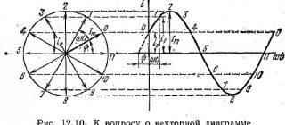
Directional principle
The arrangement of the machines and the further sequence of their operation are guided by the direction of the current. To do this, using the voltage vector, a point is specified, relative to which this vector receives a phase shift. According to this principle, the relay will be sensitive to both current and voltage. Such a circuit can be installed in both a switchable zone and a zone that cannot be switched off.
RCDs and switches are connected according to the directional principle
In the above figure, you can see that the protective device D1 and the circuit breaker it controls will respond to a short circuit at point 1, but not to a short circuit at point 2.
Rules for drawing up a selectivity map
Maximum use of the protective properties of circuit breakers is ensured by drawing up a special map showing the selectivity of the electrical network protection, with a graphic designation of all possible processes. It is carried out in the form of an established diagram, which indicates all the current characteristics of the protective devices included in a specific electrical network.
When drawing up a map, certain rules must be followed:
- All electrical installations must be connected to a common power source.
- All locations of significant design points must be clearly visible, so the selectivity map is performed at the most appropriate scale.
- The diagram shows the protective properties of each machine, as well as the characteristics of possible short circuits at various points with their minimum and maximum values.
- The characteristics of the machines are plotted sequentially, in accordance with the order in which they are connected. To correctly construct a diagram, axes with main indicators are used. Based on the diagram, a special table is compiled to facilitate the selection of protective devices.
A correctly compiled map displays a complete picture of the settings of the machines that are consistent with each other. This makes it possible to compare the parameters of protective devices and the overall selectivity of protection. The map itself is primarily built on the basis of the axes of time-current characteristics and their varieties. As a rule, this one diagram displays the parameters of two or three machines. The horizontal x-axis contains current values (in kW), and the vertical ordinate indicates time (s).
A special program that can be easily found on the Internet helps speed up the compilation of a map. Sometimes such diagrams are not included in the design documentation for electrical equipment. This can lead to violations of established standards and power outages for consumers.
2.Construction of a selectivity map
A selectivity map is a set of time-current characteristics of protections built in the same axes.
Protective devices must be located in the electrical network sequentially one after the other. As a rule, one selectivity map shows the time-current protection characteristics of two or three protective devices.
Protection selectivity maps are usually plotted on graphs with logarithmic scales. The horizontal axis represents current (A), and the vertical axis represents time (s). How to construct logarithmic axes is described in the appendix.
Figure 3.1 shows a section of the electrical network for the protection of which a selectivity map can be constructed.
Figure 3.1 – Protection layout diagram
In – rated current of the circuit breaker;
Ir – setting current for overload protection;
tr – setting of the overload protection response time;
Isd – selective cut-off current setting;
tsd – selective cut-off response time setting (time delay);
Ii – cut-off current setting.
In the event of a short circuit at points K2 and K3, the QF2 circuit breaker must trip; if the QF2 circuit breaker does not trip, the QF1 circuit breaker must trip (this is called protection redundancy), i.e. the response time of the circuit breaker QF1 must be greater than the response time of the circuit breaker QF2 at a current equal to the short circuit current at points K2 and K3. If this condition is met, then the protection is called selective.
The selectivity map also shows:
· starting currents of electrical receivers;
· minimum and maximum values of short circuit currents at various points in the circuit.
Some protection settings are selected based on these currents.
An example of a selectivity map built for circuit breakers QF1 and QF2 (diagram in Figure 3.1) is shown in Figure 3.2.
Figure 3.2 – Protection selectivity map
Judging by the selectivity map in Figure 3.2, the selectivity condition is satisfied for the maximum and minimum short circuit currents (at the beginning and at the end of the cable line to the electric motor), i.e. in case of any short circuit, the QF2 circuit breaker will operate faster than the QF1 circuit breaker and will disconnect the damaged section faster. In this case, the protection reservation condition is met, i.e. if the QF2 circuit breaker does not trip for any reason during a short circuit on the outgoing line to the engine, then the QF1 circuit breaker will trip with a specified time delay.
The QF2 circuit breaker will not trip when starting the engine (the response time is longer than the engine starting time). The motor starting current curve is shown in Figure 3.2 in a simplified manner. When starting the engine, the current decreases gradually to the rated value.