Purpose: protection of electrical objects from emergency currents occurring inside the controlled area with an absolute degree of selectivity without time delay.
Operating principle of differential protection
The measuring complex is operated by a differential organ consisting of current transformers and relays that constantly monitor the direction of currents in various areas and are triggered when they change.
In the nominal operating mode, the load current flows from the generator end to the consumers and has one direction along the entire line. It is monitored and taken into account by measuring relays. If a short circuit occurs in the controlled area, currents begin to feed it from all sides. At the end of the consumer line, the current reverses direction.
This is taken into account by the differential element: it is triggered and triggers the logical shutdown protection circuit. Differential protections work on two different principles:
It is used for power lines. Measuring current transformers and relays are installed at the ends of the line at different substations. Current circuits are connected by long cable lines.
For longitudinal differential protection, the measuring current relay is connected so that the current vectors coming from the measuring transformers are applied counter to the winding. In this case, during the nominal operating mode or the occurrence of an external short circuit outside the controlled zone, the current vectors will be mutually compensated and destroyed on the winding. There will be no reason to trigger it.
When a short circuit occurs inside the line, currents begin to flow through the winding of the current relay. It works.
More promising high-frequency differential protection (DFZ, BCHB, etc.) use the same principle, but communication between the ends of the lines to compare the directions of currents on them is carried out through communication channels due to the transmission of high-frequency pulses.
It is created for objects located at the same substation, for example, power transformers, motor blocks, generators, etc.
Measuring current transformers operate at the same substation, but at different connections of the protected object. The current relay winding is also connected counter to the direction of the line current vectors. Otherwise, the transverse differential protection repeats the operating principle of the longitudinal one.
The various types of differential protection are discussed in more detail here:
If you liked this article, share a link to it on social networks. This will greatly help the development of our site!
Subscribe to our channel on Telegram!
Just follow the link and connect to the channel.
Don't miss updates, subscribe to our social networks:
Source
Transverse differential protection
Longitudinal diff. generator protection does not operate in case of turn faults in the stator winding, since the currents passing from the main and neutral terminals are the same in this case.
Protection against turn faults is not provided for generators that do not have parallel branches in the stator winding due to the lack of simple methods for its implementation.
On powerful generators that have two or more parallel branches in the phases of the stator winding, special transverse differential protection , designed to protect the generator from turn faults in the stator winding. In this case, on the side of the zero terminals, each parallel branch must have an isolated output.
The operating principle of the transverse differential. protection is based on comparison of the geometric sum of currents in parallel phase branches of the generator stator winding.
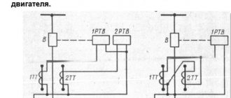
Such a comparison can be made using a three-system or single-system lateral protection scheme. Typically, a single-system circuit is used, which is performed using one current transformer installed in the circuit between two zero points of the parallel branches of the stator winding connected in a star and one relay comparing the sum of the currents of the parallel branches of all three phases of the stator winding of the generator.
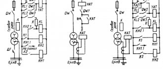
A simplified diagram of a single-system transverse differential generator protection is shown in Fig. 7-5.
In normal mode and with external short circuit. the geometric sum of the currents of each group of parallel phase branches connected in a star is equal to zero and only the unbalance current enters the protection relay.
Longitudinal differential protection of lines and its features
The features of longitudinal differential protection of lines are due to the significant distance between the ends of the protected zone. In this case, between substations A
and
B
(Fig. 10.5, a) the auxiliary wires necessary to connect the current transformers
TAI
and
TAII
located at the ends of the protected line are laid.
The protection circuit includes two sets of relays KAI
KAII
, Compliance with these requirements complicates protection, increases the cost of its implementation, and negatively affects sensitivity and reliability.
Rice. 10.5. Longitudinal differential line protection
Protection features due to auxiliary wires. In a protection circuit with circulating currents, the secondary currents of the measuring current transformers continuously flow through the auxiliary wires. Values of currents and resistance Z
The number of connecting wires determines the power supplied by the current transformers.
With a rated secondary current I
2nom = 5 A, the permissible load of the current transformers limits the resistance of the connecting wires
Z
pp>1÷2 0m. Therefore, longitudinal differential protection with an acceptable wire cross-section can be used on a line only a few hundred meters long.
For long line lengths, reducing the load on the primary measuring current transformers is achieved by reducing the current in the auxiliary wires using secondary (intermediate) current transformers TLAI
and
TLAII
(Fig. 10.5, b) with a transformation ratio
KI >
1. The specified method of reducing the load is used in typical schemes of longitudinal differential protection of lines.
In addition, the protection circuits include intermediate saturable transformers TLATI
and
TLATII,
which reduce the load on the instrument transformers during short-circuit currents.
due to an increase in the transformation ratio at saturation. The circuit uses differential DC relays KAI
and
KA1I
with rectified current braking.
At large current ratios, due to the saturation of the magnetic cores of TLAT
, the protection practically compares only the phases of the currents
İ
1I and
İ
1II (it works as a differential phase).
It is advisable to use existing telemechanics and communication cables as auxiliary wires. This eliminates the need to lay a special cable for protection, thereby dramatically reducing the cost of its implementation. In a communication cable, if it runs along the route of the protected line, when a ground fault occurs in the network, EMFs arise, which can pose a danger to maintenance personnel and relay protection and automation equipment. This danger is eliminated thanks to the use of TLA transformers,
separating the relay circuits from the auxiliary wires.
To implement protection that operates for all types of short circuits depending on the ratio of total phase currents at the ends of the protected line, it is necessary to have six differential relays and at least four auxiliary wires. As the length of the auxiliary wires increases, the likelihood of damage increases, resulting in failure or incorrect operation of the protection. To reduce the number of auxiliary wires and differential relays, combined filters of symmetrical current components AZI
and
AZII,
at the output of which the currents are proportional to
İ
1+
k
2
İ
2. Protection has slightly worse performance with a filter
İ
1+
k
0
İ
0
,
especially reduced sensitivity to two-phase short circuits.
The use of combined filters makes it possible to reduce the number of differential relays and the number of auxiliary wires to two and thereby reduce the likelihood of communication failure between current transformers. To prevent false alarms and failures when auxiliary wires are damaged, the protection is equipped with special devices for monitoring their serviceability.
Protection features due to two sets of differential relays. Secondary currents I
2I and
I
2II are distributed between parallel-connected relay windings
KAI
and
KAII
(Fig. 10.5, a).
In this case, for current I
2I, the resistance of the auxiliary wires
Z
np is connected in series with the resistance of the relay
KAII,
and for current
I
2II - in series with the resistance of the relay
KAI.
In this regard, most of the current
I
2I and a smaller part of the current
I
2I pass in the winding of the first relay, and vice versa in the winding of the second relay, i.e.
a smaller part of the current I
2I and a larger part of the current
I
2II passes.
Thus, even in the absence of errors in the current transformers, unbalance currents pass through the relay during normal operation and external short circuits, due to the unequal distribution of secondary currents between the relay windings. As the resistance of the auxiliary wires increases, the unbalance currents increase, which requires a corresponding hardening of the protection.
During short circuits in the zone, the current in each relay is only part of the total fault current, since the second part of it passes through the winding of the second relay. In this regard, the sensitivity of the protection decreases. To increase the reliability and sensitivity of protection, differential current relays with braking are used. Unbalance currents can be reduced using additional resistance that compensates for the influence of the communication line. However, such compensation does not provide selectivity of protection with a significant length of auxiliary wires.
Longitudinal differential protection of lines type DZL-2. The DZL-2 protection circuit uses a combined filter, the output current of which is proportional to İ
1—
k
2
İ
2. A polarized relay of type RP7 with two windings - working and braking - is used as a differential relay.
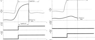
The working winding is connected to rectifier VS
1
,
the input of which is supplied with a voltage proportional to the voltage on the auxiliary wires (Fig. 10.5, b), and the brake winding is connected to rectifier VS2
connected to a current proportional to the current circulating through the auxiliary wires.
At currents I
n < 2.5
I
s.z., the protection compares the absolute values and phases of currents
İ
1I and
İ
1II, and at large multiples of the short-circuit current.
Due to the saturation of TLAT
, as indicated, only the phases of the currents are compared. The protection has high-speed automatic control, which takes it out of action if the auxiliary wires are damaged, as well as automatic and periodic monitoring of the insulation resistance of the auxiliary wires relative to the ground. Protection type DZL-2 is intended for use as the main one for all types of short circuits in power transmission lines up to 20 km long (without branches) in networks with solidly grounded neutrals. To use protection in networks with neutrals isolated or grounded through arc suppression reactors, appropriate switching of the current filter circuits is carried out, ensuring increased protection sensitivity and preferential shutdown of one damaged line in case of double ground faults [51].
Evaluation of longitudinal differential protection of lines. Longitudinal differential protection does not require current and time detuning from the protection of adjacent sections, does not react to swings, and provides selective and time-delayed shutdown of the damaged section in a network of any configuration. For short sections, the protection is relatively simple, fairly reliable and meets sensitivity requirements.
As the length of the protected zone increases, the protection acquires negative properties, which are due to the influence of the large length of auxiliary wires on its operation: the cost of protection increases sharply due to the high costs of the connecting cable and its installation; the possibility of damage to auxiliary wires and, as a result, incorrect operation or failure of the protection increases. Therefore, there is a need for a special device that monitors the serviceability of auxiliary wires. In addition, an additional unbalance current appears due to the unequal distribution of secondary currents between the two relays connected at the ends of the protected line;
To increase the sensitivity of protection, it is necessary to use differential relays with braking. All this leads to complication of protection.
Longitudinal differential protection, according to its operating principle, does not respond to external short circuits, therefore it cannot provide backup in the event of damage to adjacent elements. In this regard, installing differential protection as the only one is unacceptable. The noted disadvantages limit the use of longitudinal differential protection on power lines. In distribution networks, the required sensitivity, selectivity and speed of action are often provided by simpler current and current directional protection in combination with automation means.
The features of longitudinal differential protection of lines are due to the significant distance between the ends of the protected zone. In this case, between substations A
and
B
(Fig. 10.5, a) the auxiliary wires necessary to connect the current transformers
TAI
and
TAII
located at the ends of the protected line are laid.
The protection circuit includes two sets of relays KAI
KAII
, Compliance with these requirements complicates protection, increases the cost of its implementation, and negatively affects sensitivity and reliability.
Rice. 10.5. Longitudinal differential line protection
Protection features due to auxiliary wires. In a protection circuit with circulating currents, the secondary currents of the measuring current transformers continuously flow through the auxiliary wires. Values of currents and resistance Z
The number of connecting wires determines the power supplied by the current transformers.
With a rated secondary current I
2nom = 5 A, the permissible load of the current transformers limits the resistance of the connecting wires
Z
pp>1÷2 0m. Therefore, longitudinal differential protection with an acceptable wire cross-section can be used on a line only a few hundred meters long.
For long line lengths, reducing the load on the primary measuring current transformers is achieved by reducing the current in the auxiliary wires using secondary (intermediate) current transformers TLAI
and
TLAII
(Fig. 10.5, b) with a transformation ratio
KI >
1. The specified method of reducing the load is used in typical schemes of longitudinal differential protection of lines.
In addition, the protection circuits include intermediate saturable transformers TLATI
and
TLATII,
which reduce the load on the instrument transformers during short-circuit currents.
due to an increase in the transformation ratio at saturation. The circuit uses differential DC relays KAI
and
KA1I
with rectified current braking.
At large current ratios, due to the saturation of the magnetic cores of TLAT
, the protection practically compares only the phases of the currents
İ
1I and
İ
1II (it works as a differential phase).
It is advisable to use existing telemechanics and communication cables as auxiliary wires. This eliminates the need to lay a special cable for protection, thereby dramatically reducing the cost of its implementation. In a communication cable, if it runs along the route of the protected line, when a ground fault occurs in the network, EMFs arise, which can pose a danger to maintenance personnel and relay protection and automation equipment. This danger is eliminated thanks to the use of TLA transformers,
separating the relay circuits from the auxiliary wires.
To implement protection that operates for all types of short circuits depending on the ratio of total phase currents at the ends of the protected line, it is necessary to have six differential relays and at least four auxiliary wires. As the length of the auxiliary wires increases, the likelihood of damage increases, resulting in failure or incorrect operation of the protection. To reduce the number of auxiliary wires and differential relays, combined filters of symmetrical current components AZI
and
AZII,
at the output of which the currents are proportional to
İ
1+
k
2
İ
2. Protection has slightly worse performance with a filter
İ
1+
k
0
İ
0
,
especially reduced sensitivity to two-phase short circuits.
The use of combined filters makes it possible to reduce the number of differential relays and the number of auxiliary wires to two and thereby reduce the likelihood of communication failure between current transformers. To prevent false alarms and failures when auxiliary wires are damaged, the protection is equipped with special devices for monitoring their serviceability.
Protection features due to two sets of differential relays. Secondary currents I
2I and
I
2II are distributed between parallel-connected relay windings
KAI
and
KAII
(Fig. 10.5, a).
In this case, for current I
2I, the resistance of the auxiliary wires
Z
np is connected in series with the resistance of the relay
KAII,
and for current
I
2II - in series with the resistance of the relay
KAI.
In this regard, most of the current
I
2I and a smaller part of the current
I
2I pass in the winding of the first relay, and vice versa in the winding of the second relay, i.e.
a smaller part of the current I
2I and a larger part of the current
I
2II passes.
Thus, even in the absence of errors in the current transformers, unbalance currents pass through the relay during normal operation and external short circuits, due to the unequal distribution of secondary currents between the relay windings. As the resistance of the auxiliary wires increases, the unbalance currents increase, which requires a corresponding hardening of the protection.
During short circuits in the zone, the current in each relay is only part of the total fault current, since the second part of it passes through the winding of the second relay. In this regard, the sensitivity of the protection decreases. To increase the reliability and sensitivity of protection, differential current relays with braking are used. Unbalance currents can be reduced using additional resistance that compensates for the influence of the communication line. However, such compensation does not provide selectivity of protection with a significant length of auxiliary wires.
Longitudinal differential protection of lines type DZL-2. The DZL-2 protection circuit uses a combined filter, the output current of which is proportional to İ
1—
k
2
İ
2. A polarized relay of type RP7 with two windings - working and braking - is used as a differential relay.
The working winding is connected to rectifier VS
1
,
the input of which is supplied with a voltage proportional to the voltage on the auxiliary wires (Fig. 10.5, b), and the brake winding is connected to rectifier VS2
connected to a current proportional to the current circulating through the auxiliary wires.
At currents I
n < 2.5
I
s.z., the protection compares the absolute values and phases of currents
İ
1I and
İ
1II, and at large multiples of the short-circuit current.
Due to the saturation of TLAT
, as indicated, only the phases of the currents are compared. The protection has high-speed automatic control, which takes it out of action if the auxiliary wires are damaged, as well as automatic and periodic monitoring of the insulation resistance of the auxiliary wires relative to the ground. Protection type DZL-2 is intended for use as the main one for all types of short circuits in power transmission lines up to 20 km long (without branches) in networks with solidly grounded neutrals. To use protection in networks with neutrals isolated or grounded through arc suppression reactors, appropriate switching of the current filter circuits is carried out, ensuring increased protection sensitivity and preferential shutdown of one damaged line in case of double ground faults [51].
Evaluation of longitudinal differential protection of lines. Longitudinal differential protection does not require current and time detuning from the protection of adjacent sections, does not react to swings, and provides selective and time-delayed shutdown of the damaged section in a network of any configuration. For short sections, the protection is relatively simple, fairly reliable and meets sensitivity requirements.
As the length of the protected zone increases, the protection acquires negative properties, which are due to the influence of the large length of auxiliary wires on its operation: the cost of protection increases sharply due to the high costs of the connecting cable and its installation; the possibility of damage to auxiliary wires and, as a result, incorrect operation or failure of the protection increases. Therefore, there is a need for a special device that monitors the serviceability of auxiliary wires. In addition, an additional unbalance current appears due to the unequal distribution of secondary currents between the two relays connected at the ends of the protected line;
To increase the sensitivity of protection, it is necessary to use differential relays with braking. All this leads to complication of protection.
Longitudinal differential protection, according to its operating principle, does not respond to external short circuits, therefore it cannot provide backup in the event of damage to adjacent elements. In this regard, installing differential protection as the only one is unacceptable. The noted disadvantages limit the use of longitudinal differential protection on power lines. In distribution networks, the required sensitivity, selectivity and speed of action are often provided by simpler current and current directional protection in combination with automation means.
8.1. Purpose and types of differential protection
On lines extending from the busbars of power plants or hub substations, stability conditions often require that short-circuits be disconnected within the entire protected line without a time delay. This requirement cannot be met using instantaneous current cut-offs that protect only part of the line. In addition, cutoffs are not applicable due to the selectivity condition on short power lines, where the short-circuit currents at the beginning and end of the line are approximately the same. In these cases, differential protection (DP) is used, which provides instantaneous switching off of a short circuit at any point in the protected area and does not operate in case of a short circuit outside the coverage area.
Differential protections are divided into:
longitudinal – for protection of both single and parallel lines;
transverse - to protect only parallel lines.
Typical longitudinal DZL[edit]
On an electromechanical base with a wired communication channel: DZL-1, DZL-2. On a microprocessor base with an optical communication channel: - domestically produced ShE2607 09x, ShE2710 591 (NPP EKRA), Sh2600 05.52x, Sh2700 05.62X (Relematika); — foreign production UR L90 (General Electric), P541-546 (Alstom), RED 670 (ABB), 7SD522 (Siemens).
Transverse differential line protection
(transverse DZL) is connected to the difference in currents of parallel lines. During an external short circuit, currents of equal magnitude and direction flow through parallel power lines, and therefore the differential current in the protection is zero. During a short circuit on one of the lines, the differential current acquires a significant value, sufficient to trigger the protection. To determine the circuit to be switched off, the power direction element is used in the protection. Transverse differential line protection is used to protect parallel lines with the same or slightly different parameters. Protection is not very widespread and again, as a rule, is not installed.
Materials
.
Fedoseev A.M., Fedoseev M.A. Relay protection of electrical power systems. Textbook for universities. – 2nd ed., revised. and additional.. – M.: Energoatomizdat, 1992. – 528 p.: ill.
Protection relay designs and circuit applications
In very long power lines, a circuit is used in which there is a protective relay that has a special design. With its help, you can ensure a normal level of sensitivity, and use standard connecting wires. Transverse differential protection is triggered by comparing the current in two lines by phase and magnitude.
High-speed differential protection is used in power lines carrying voltage in the range of 3-35 thousand volts. This ensures reliable protection against phase-to-phase short circuits. The differential protection is performed as two-phase due to the fact that the electrical network with the above-mentioned operating voltages is not grounded by neutrals. Or the neutral is connected to ground via an arc suppression coil.
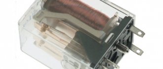
Differential machines
The same type of protective devices includes household differential circuit breakers, which combine the functions of a circuit breaker and an RCD. Typically, these devices are designed in one common housing with combined performance characteristics (see photo below in the text).
Differential automatic
According to the principle of operation, all protective devices of this class are divided into electronic and electromechanical, and according to their design, they can be built into the machine or manufactured separately. It is important for a person unenlightened in the intricacies of electrical engineering to learn to distinguish between a conventional RCD and a differential circuit breaker, since this may ultimately affect its safety.
The fact is that when an electronic RCD is connected to the supply circuit, one mandatory requirement must be met, which is the need to constantly keep this line energized. If there is no adequate power supply for any reason, the protection system will not work when a leakage current appears.
Note! This situation often occurs in the event of a break in the internal power supply circuit of the switch or damage to the zero outside the facility.
In an electromechanical type RCD, the protective operation of the device is guaranteed in any situation.
In the final part of the review of differential protection systems, it should be noted that its use helps to increase the safety and reliability of electrical equipment and power lines. The widespread introduction of modern electronic technologies into power supply systems makes it possible to take into account the operating features of the vast majority of known electrical devices. This helps to increase the speed of protection response, and also significantly increases the effectiveness of its action.