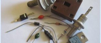
International Rectifier has introduced a new line of 15 and 20 V Schottky diodes for servo and telecom applications, which are designed for rectification in the secondary circuits of RF converters, including OR circuits with low forward voltage drop.
The value of the forward voltage drop of the new IR diodes is 25% lower than existing industrial analogues, in addition, the reverse leakage current parameter has been reduced by 14%, which will allow developers to achieve maximum efficiency of the entire system and reduce power losses.
80CPTN015 diode (TO-247 package) is made using groove technology, has an operating voltage of 15 V and can withstand high junction temperatures of up to 150°C. Compared to similar industry standards, the 80CPTN015 IR Schottky diode has 12% lower forward voltage drop and 68% lower reverse leakage current. The maximum forward voltage drop is 340 mV at 40 A load (125°C). This reduces power dissipation by 10% and makes the 80CPTN015 the best choice for 5V rectification applications where efficiency is critical.
The 80CPT015 diode has a nominal parameters of 15 V / 80 A, also based on groove technology, the forward voltage drop is 270 mV at a temperature of 125 ° C. The ultra-low forward voltage drop makes the diode ideal for RF converter and 1.5V power supply applications. The TO-247 diode has 20% improved forward voltage drop performance and 14% less reverse leakage current than typical diodes Schottky. This 80CPT015 the best solution for rectifying ORing circuits, as well as for circuits with output voltages up to 12 V.
The 60CTT015 and 60CTTN015 diodes are TO-220 packaged and rated at 15 V, with a typical forward voltage drop of 0.28 V at 30 A and 0.33 V at 60 A. The 60CTT015 is an ORing Schottky diode and is designed for applications where low forward voltage is required. voltage drop. The 60CTTN015 minimum reverse leakage current of 250 mA (125°C) allows it to be used in applications with temperature transitions up to 150°C.
80CNT020 diode is made in a D61 package, rated for an input voltage of 20 V, the voltage drop is 240 mV at 125 ° C, which is 25% lower than industry standards. The diode is designed for high-precision ORing applications with an output of up to 15 V. Operating temperature range: -55 ... + 125 ° C
Read also: What is the tailstock of a lathe used for?
Date: 06/14/2018 //
For homemade circuits, radio amateurs often use rectifier bridges based on Schottky diodes. The use of Schottky diodes in bridges is due to the low voltage drop across the diode, which entails lower losses on the bridge and reduces its heating. Most Schottky diodes are produced as dual diodes, in packages with a common cathode , and assembling a bridge from such a diode leads a beginner to a dead end. Today we will look at how you can assemble a diode bridge from Schottky diodes.
Diode bridge of four Schottky diodes
The easiest way to assemble a bridge using Schottky diodes is to connect the anodes of the diode assembly and get a regular one from a dual diode. This option will allow you to fully use both diodes of each diode assembly.
Diode bridge of three Schottky diodes
When selecting Schottky diodes for a bridge, you need to take into account that manufacturers indicate the maximum current of the diode assembly, and not of each diode that is included in it. the MBR20100CT diode assembly is designed for a current of 20A , then each of the two diodes is designed for 10A . If the parameters of the diode assemblies used allow, you can save a little and build a diode bridge from just three Schottky diodes.
Diode bridge of two Schottky diodes
is IMPOSSIBLE to build a diode bridge from two Schottky diodes with a common cathode . It is necessary to have a diode with a common cathode and a common anode . It is extremely difficult to buy Schottky diodes with a common anode; they are very rarely found on sale. If you manage to purchase them, the bridge diagram will look like this.
Metal-semiconductor junction diodes, theoretically described by Walter Schottky in the 1930s, are now used where their efficient electrical properties, such as low junction voltage drop (VF) and fast switching speed (tRR), are required.
But these benefits come at a price. The main disadvantage of Schottky diodes is related to the relatively high leakage current. Leakage current, referred to in foreign sources as 'IR' (reverse current), is usually measured in microamps (10 -6 A) for small Schottky diodes and can reach several milliamps (10 -3 A) for larger diodes. Compared to Schottky diodes, pn junction diodes (semiconductor-semiconductor) with low leakage have this parameter in the nanoampere range (10 -9 A), and more powerful diodes have a leakage current of several microamps.
Read also: Homemade devices for circular saws
In battery-powered devices such as smartphones, tablets and smartwatches, this disadvantage of Schottky diodes reduces battery life. To solve the problem, transistors based on the Schottky effect were used - with the same low forward voltage at the junction, but with a lower leakage current. In some cases, this approach was successful, but it was necessary to sacrifice another important parameter of Schottky diodes - fast switching time. Additional difficulties arose in the process of manufacturing devices, since it was necessary to use more complex CMOS technologies.
To come in
Already registered? Sign in here.
There are currently 0 users on the page
There are no users viewing this page.
Semiconductors are substances that occupy an intermediate position between conductors and insulators in their electrically conductive properties. In semiconductors, as in metals, current is the ordered movement of charged particles. However, along with the movement of negative charges (electrons) in semiconductors, there is an ordered movement of positive charges, the so-called. - holes.
Holes are formed with the participation of ions of the semiconductor substance - atoms with escaped electrons. In reality, ionized atoms do not leave their place in the crystal lattice. In fact, there is a gradual change in the state of the atoms of a substance when electrons jump from one atom to another. A process arises that outwardly looks like the ordered movement of certain conventional positively charged particles - holes.
In an ordinary, pure semiconductor, the ratio of holes and free electrodes is 50%:50%. But as soon as a small amount of a substance – an impurity – is added to the semiconductor, this ratio undergoes significant changes. Depending on the characteristics of the added substance, the semiconductor acquires either pronounced electronic conductivity (n-type), or holes (p-type) become its main carriers.
A semiconductor junction (pn) is formed at the junction of two fragments of semiconductor material having different conductivities. It is an extremely thin region, depleted of carriers of both types. A pn junction has little resistance when the current direction is forward, and a very high resistance when the current direction is reverse.
A conventional semiconductor diode consists of one semiconductor junction equipped with two terminals - an anode (positive electrode) and a cathode (negative electrode). Accordingly, the diode has the property of one-way conductivity - it conducts current well in the forward direction and poorly in the reverse direction.
What does this mean in practice? Let's imagine an electrical circuit consisting of a battery and an incandescent light bulb connected in series through a semiconductor diode. The light bulb will light only if the anode (positive electrode) is connected to the plus of the power source (battery) and the cathode (negative electrode) to the minus - through the filament of the light bulb.
This is the direct connection of a semiconductor diode. If you reverse the polarity of the power source, the diode will turn on in reverse - the light bulb will not light
Pay attention to how the designation of a semiconductor diode looks on the diagram - a triangular arrow indicating direct connection coincides with the direction of current generally accepted in electrical engineering - from the plus of the power source to the minus. The vertical line adjacent to it symbolizes a barrier to the flow of current in the opposite direction
There is one prerequisite for the normal operation of any semiconductor diode. The power supply voltage must exceed a certain threshold (the value of the internal bias potential of the pn junction). For rectifier diodes it is usually less than 1 volt, for germanium high-frequency diodes it is about 0.1 volt, for LEDs it can exceed 3 volts. This property of semiconductor diodes can be used to create low-voltage stabilized power supplies.
If you connect the diode back and gradually increase the voltage of the power supply, at some point a reverse electrical breakdown of the pn junction will definitely occur. The diode will begin to pass current in the opposite direction, and the junction will be damaged. The value of the maximum permissible reverse voltage (Urev.i.) varies widely among different types of semiconductor diodes and is a very important parameter.
The second, no less important parameter can be called the limiting value of the forward current - Upr. This parameter directly depends on the magnitude of the voltage drop across the junction of the semiconductor diode, the semiconductor material and the heat transfer characteristics of the housing.
Current detection
There are several methods to accomplish this. Let's consider the simplest of them. To determine the current rating of an LED, you will need a tester called a multimeter. This method is also used for conventional diodes.
LED current measurement
Testing is carried out as follows:
- The multimeter probes are connected with the positive terminal to the anode, and the negative terminal to the cathode.
- The anode lead of the LED is made longer than the cathode lead.
- You can ring LEDs that have a low supply voltage. If they have high power, this method cannot be used.
It is better to use a proven method of measuring device characteristics. For this you will need:
- power supply rated for 12 V;
- multi-amperemeter;
- fixed resistors - 2.2 and 1 kOhm, as well as 560 Ohm;
- variable resistor – 470–680 Ohm;
- voltmeter, preferably digital;
- wires for switching the circuit.
As in the previous case, you will need to find out the polarity of the diode. If it is not clear from its terminals where “+” and “-” are, then you will have to connect a 2.2 kOhm resistor to one of the terminals. After this, you need to connect the LED to the power supply. When it lights up, you need to turn off the power and mark the desired output “+”.
Now you need to replace the 2.2 kOhm resistor with a 560 Ohm one. A variable resistor is connected in series to this circuit, as well as a milliammeter for measuring. A voltmeter with a resolution of 0.1 V is connected in parallel with the LED. After this, you need to set the maximum resistance of the variable resistor.
Multimeter for measuring LED current and voltage
You can connect the assembled circuit to the power supply, observing the polarity. After switching on, the LED will have a dim glow. The resistance is gradually reduced and monitored with a voltmeter. For a certain time, the voltage will increase to 0.5 V, and the current will also increase, which affects the increase in the brightness of the LED. It is necessary to record readings every 0.1 V. The optimal operating current will be achieved when the voltage increases slower than the current and the brightness stops increasing.
Types of diodes.
In addition to the ability to pass current in only one direction, the pn junction has a number of other interesting features. For example, the ability to emit (including in the visible range) when current flows in the forward direction and generate electricity. current under the influence of radiation. This feature is used in the implementation of electronic elements such as LEDs, photodiodes and photocells. In addition, any pn junction also has an electrical capacitance, and in addition, the ability to change it using a voltage applied in the opposite direction. Using it, it was possible to create such useful elements as VARICAPS.
Varicaps.
So, a pn junction has an electrical capacitance, the value of which depends on its area and width. If the voltage is applied in the opposite direction, the junction shifts, the area remains unchanged, but the width increases. The capacity decreases accordingly. It becomes possible to regulate this capacity by changing the magnitude of the applied voltage. Electronic elements (diodes, essentially) created on this principle are called varicaps.
Varicaps are used in radio equipment instead of conventional variable capacitors to adjust the frequency of oscillatory circuits. Advantage The use of varicaps has made it possible to significantly reduce the size and increase the efficiency of selection units for radio receiving devices, and it is relatively simple and inexpensive to implement automation of setup processes (previously carried out manually).
Schottky diodes.
Schottky diode (Schottky barrier diode) is a semiconductor diode with a low voltage drop (0.2-0.4 volts) when connected directly. Named after the German physicist Walter Schottky. In Schottky diodes, unlike conventional diodes, instead of a pn junction, a metal-semiconductor junction is used. This provides a number of special advantages - reduced voltage drop during direct connection, very low reverse recovery charge.
The latter is explained by the fact that, unlike conventional diodes, Schottky diodes operate only on main carriers, and their performance is limited only by the barrier capacitance. Schottky diodes are best used in high-speed pulse circuits, for rectifying low high-frequency voltages, in high-frequency mixers, in switches and switches.
LEDs.
When direct current flows through any pn junction (any diode!) photons are generated. This is a consequence of cyclic recombination - the restoration of atoms of a substance in the process of movement of the main current carriers. Electronic elements used to generate light and based on this principle are called LEDs. LEDs are used for indication and information transmission, as part of electronic devices such as optocouplers.
Efficiency and the brightness of modern LEDs is so high that at the moment they are the most promising sources of artificial lighting. Depending on the material chosen as a semiconductor, LEDs emit at different wavelengths. IR diodes emit in the infrared region, indicator and lighting LEDs emit in the visible part of the spectrum (green, red, yellow, etc.). The highest efficiency LEDs are distinguished by emitting in the ultraviolet region. Interestingly, this type is most often used for lighting. White light is obtained by using a special phosphor that converts ultraviolet light.
The intensity of the LED radiation increases with increasing current flowing through the pn junction, up to a certain limit. After reaching it, the LED fails. Therefore, for normal operation it is necessary to limit the current. Typically, this is accomplished by connecting a resistor in series.
Stabilizers.
Existing zener diodes are limited by the minimum stabilization voltage (about 3 V). What to do if you need a source of stabilized voltage up to 3 volts? Use the direct branch of the Volt - Ampere Characteristics of the diode (VAC). In the region of forward bias of the pn junction, the voltage across it can have a value of 0.7. 2 V (depending on the semiconductor material) and depends little on current. Diodes specially used in this capacity are called STABITORS.
Device
Below is a detailed description of the diode structure; studying this information is necessary for further understanding of the principles of operation of these elements:
- The housing is a vacuum cylinder that can be made of glass, metal or durable ceramic varieties of material.
- inside the cylinder . The first is a heated cathode, which is designed to ensure the process of electron emission. The simplest cathode in design is a filament with a small diameter, which heats up during operation, but today indirectly heated electrodes are more common. They are cylinders made of metal and have a special active layer capable of emitting electrons.
- Inside the indirectly heated there is a specific element - a wire that glows under the influence of electric current, it is called a heater.
- The second electrode is the anode, it is needed to receive the electrons that were released by the cathode. To do this, it must have a potential that is positive relative to the second electrode. In most cases, the anode is also cylindrical.
- Both electrodes of vacuum devices are completely identical to the emitter and base of the semiconductor variety of elements.
- Silicon or germanium is most often used to make a diode crystal One of its parts is p-type electrically conductive and has a deficiency of electrons, which is formed by an artificial method. The opposite side of the crystal also has conductivity, but it is n-type and has an excess of electrons. There is a boundary between the two regions, which is called a pn junction.
Such features of the internal structure give diodes their main property - the ability to conduct electric current in only one direction.
Execution options
Zener diode
Today, a semiconductor diode can be represented by various types of devices. Their classification is based on the operating principle, material of manufacture, etc. There is also a classification based on the area of application. According to it, the following types of diodes are distinguished:
- pulse;
- Zener diodes;
- point;
- alloy;
- laser;
- LEDs;
- varicaps and other types.
A special abstract will tell you about each type in more detail, indicating the features of operation, current-voltage characteristics, properties, etc. for each type.
In addition, there is another classification of these products based on their functional purpose:
- rectifying Such diodes are designed to rectify alternating current. Here the rectification coefficient will be equal to the ratio of the forward and reverse currents (the voltage is equal);
- high frequency. As a rule, they are subject to research related to the operation of ultrahigh and high frequency devices. Often used for detecting and modeling ultra-high-frequency oscillations. The frequency can reach hundreds of megahertz;
- varicaps. Their operating principle is based on changing the properties of the electron-hole junction capacitance. The capacitance may vary depending on the reverse applied voltage;
- tunnel Here, the enhancement of the tunneling effect of the pn junction is achieved through the use of high concentrations of various dopants.
This classification is used most often. Also, the types of diodes differ in design. They can be:
- flat;
- point;
- microalloy
Divided according to power, the following types are distinguished:
- powerful;
- medium power;
- low-power.
According to the frequency parameter, these products are divided into:
- high frequency;
- low frequency;
- Microwave.
Variety of diodes
Semiconductor diodes have a large number of divisions by class, power, frequency and other parameters, which demonstrates their wide application.
Schottky diode in RF circuits
Schottky diodes also have fast switching speed. This means we can use them in high frequency (RF) circuits.
So, let's take a frequency generator and set the sine frequency to 60 Hz
Let's take a 1N4007 diode and a 1N5817 Schottky diode. Let's connect them using a simple half-wave rectifier circuit
and we will take evidence from them
As you can see, both of them do an excellent job of rectifying the signal at a frequency of 60 Hz.
But what happens if we increase the frequency to 300 kHz?
How to determine the polarity of an LED - 2 simple ways
LED is a semiconductor optical device that transmits electric current in the forward direction. When connected inversely, there will be no current in the circuit, and, naturally, no glow will occur. To prevent this from happening, you need to maintain the polarity of the LED.
The LED in the diagram is indicated by a triangle in a circle with a crossbar - this is the cathode, which has a “-” (minus) sign. On the opposite side there is an anode with a “+” (plus) sign.
LED designation in the circuit
Wiring diagrams must include a pinout (or pinout) to identify all connection contacts.
How to determine the polarity of a diode while holding a tiny light bulb in your hands? After all, for a correct connection you need to know where it is minus and where it is plus. If the pinout is mixed up, the circuit will not work.
Visual method for determining polarity
The first method of determination is visual. The diode has two terminals. The short leg will be the cathode; the anode of the LED is always longer. It’s easy to remember, since the initial letter “k” is present in both words.
LED Lead Length
When both pins are bent or the device is removed from another board, their length can be difficult to determine. Then you can try to see a small crystal in the case, which is made of transparent material. It is located on a small stand. This pin corresponds to the cathode.
Also, the LED cathode can be identified by a small notch. New models of LED strips and lamps use surface-mount semiconductors. The existing bevel key indicates that this is a negative electrode (cathode).
Sometimes LEDs are marked “+” and “-”. Some manufacturers mark the cathode with a dot, sometimes a green line. If there is no mark or it is difficult to see because the LED was removed from another circuit, you need to test.
Testing with a multimeter or battery
It's good if you have a multimeter at hand. Then the polarity of the LED will be determined in one minute. Having selected the ohmmeter mode (resistance measurement), it is easy to perform the following action. By applying the probes to the legs of the LED, the resistance is measured. The red wire should be connected to the positive, and the black wire to the negative.
When turned on correctly, the device will produce a value approximately equal to 1.7 kOhm, and a glow will be observed. When turned back on, the multimeter display will display an infinitely large value. If the test shows that the diode shows low resistance in both directions, then it is broken and should be discarded.
Determining LED polarity using a multimeter
Some devices have a special mode. It is designed to check the polarity of the diode. Direct switching will be signaled by a backlit diode. This method is suitable for red and green semiconductors.
Blue and white LEDs only provide an indication at voltages greater than 3 volts, so the desired result cannot be achieved. To test them, you can use multimeters like DT830 or 831, which have a mode for determining the characteristics of transistors.
Using the PNP part, one lead of the LED is inserted into the collector socket, the second into the emitter hole. In case of direct connection, an indication will appear; inverse connection will not give a similar effect.
How to determine the polarity of an LED if you don’t have a multimeter at hand? You can resort to a regular battery or accumulator. For this you will need any other resistor. This is necessary to protect the LED from breakdown and failure. A series-connected resistor, the value of which should be approximately 600 Ohms, will limit the current in the circuit.
Checking polarity using the power supply
And a few more tips:
- If the polarity of the LED is known, it is no longer possible to apply reverse voltage to it. Otherwise, there is a risk of breakdown and failure. With proper use, the LED will serve well, since it is durable, and its housing is well protected from moisture and dust;
- Some types of LEDs are sensitive to static electricity (blue, violet, white, emerald). Therefore, they need to be protected from the influence of “statics”;
- When testing an LED with a multimeter, it is advisable to perform this action quickly; touching the terminals should be short-term in order to avoid breakdown of the diode and its failure.
Correct LED activation
An LED is a diode that lights up when current flows through it. In English, an LED is called a light emitting diode, or LED.
The color of the LED glow depends on the additives added to the semiconductor. For example, impurities of aluminum, helium, indium, and phosphorus cause a glow from red to yellow. Indium, gallium, nitrogen makes the LED glow from blue to green. When a phosphor is added to a blue crystal, the LED will glow white. Currently, the industry produces LEDs of all colors of the rainbow, but the color does not depend on the color of the LED housing, but on the chemical additives in its crystal. An LED of any color can have a transparent body.
The first LED was manufactured in 1962 at the University of Illinois. In the early 1990s, bright LEDs appeared, and a little later, super bright ones. The advantages of LEDs over incandescent light bulbs are undeniable, namely:
- * Low power consumption - 10 times more economical than light bulbs * Long service life - up to 11 years of continuous operation * High durability - not afraid of vibrations and shocks * Wide variety of colors * Ability to work at low voltages * Environmental and fire safety - no toxic substances in LEDs . LEDs do not heat up, which prevents fires.
LED markings
Rice. 1.
Design of 5 mm indicator LEDs
An LED crystal is placed in the reflector. This reflector sets the initial scattering angle. The light is then passed through an epoxy resin housing. It reaches the lens - and then it begins to scatter on the sides at an angle depending on the design of the lens, in practice - from 5 to 160 degrees.
Emitting LEDs can be divided into two large groups: visible LEDs and infrared (IR) LEDs. The former are used as indicators and illumination sources, the latter - in remote control devices, infrared transceivers, and sensors. Light-emitting diodes are marked with a color code (Table 1). First, you need to determine the type of LED by the design of its housing (Fig. 1), and then clarify it by color markings in the table.
Rice. 2.
Types of LED housings
LED colors
LEDs come in almost every color: red, orange, amber, amber, green, blue and white. Blue and white LED are a little more expensive than other colors. The color of LEDs is determined by the type of semiconductor material from which it is made, and not by the color of the plastic of its housing. LEDs of any color come in a colorless case, in which case the color can only be found out by turning it on...
Table 1.
LED markings
Multicolor LEDs
A multicolor LED is designed simply; as a rule, it is red and green combined into one housing with three legs. By changing the brightness or the number of pulses on each crystal, you can achieve different glow colors.
LEDs are connected to a current source, anode to positive, cathode to negative. The negative (cathode) of an LED is usually marked with a small cut of the body or a shorter lead, but there are exceptions, so it is better to clarify this fact in the technical characteristics of a particular LED.
In the absence of these marks, the polarity can be determined experimentally by briefly connecting the LED to the supply voltage through the appropriate resistor. However, this is not the best way to determine polarity. In addition, in order to avoid thermal breakdown of the LED or a sharp reduction in its service life, it is impossible to determine the polarity “at random” without a current-limiting resistor. For quick testing, a resistor with a nominal resistance of 1k ohms is suitable for most LEDs as long as the voltage is 12V or less.
When connecting an LED, the polarity must be observed, otherwise the device may be damaged. The breakdown voltage is specified by the manufacturer and is usually more than 5 V for a single LED. Why? As is clear from the name, an LED is not a rectifying diode, and although they share the property of passing current in one direction, there is a significant difference between them. In order for an LED to emit in the visible range, it has a significantly wider bandgap than a conventional diode. And the parasitic parameter of diodes, such as internal capacitance, directly depends on the band gap. When the direction of the current changes, this capacitance is discharged over a period of time, called the closing time, depending on the size of this capacitance. During a capacitance discharge, the LED crystal experiences significant peak loads for a much longer time than a conventional diode. With a subsequent change in the direction of the current to the “correct” one, the situation repeats. Since the turn-on/off time of conventional diodes is much shorter, it is necessary to use them in AC circuits, including in series with LEDs, to reduce the negative influence of alternating current on the LED chip. If the LED product does not have built-in reverse polarity protection, then a connection error will also lead to a decrease in service life. Some LEDs have a current-limiting resistor built into them “from the factory” and can immediately be connected to a 12 or 5 volt source, but such LEDs are quite rare and most often it is necessary to connect an external current-limiting resistor to the LED.
A word of warning: do not point the LED beam directly at your eye (or your friend’s eye) at close range, as this can damage your vision.
Supply voltage
The two main characteristics of LEDs are voltage drop and current. Typically, LEDs are designed for a current of 20 mA, but there are exceptions, for example, quad-chip LEDs are usually designed for 80 mA, since one LED housing contains four semiconductor crystals, each of which consumes 20 mA. For each LED, there are permissible values of supply voltage Umax and Umaxrev (for direct and reverse switching, respectively). When voltages above these values are applied, an electrical breakdown occurs, as a result of which the LED fails. There is also a minimum value of the supply voltage Umin at which the LED glows. The range of supply voltages between Umin and Umax is called the “working” zone, since this is where the LED operates.
Supply voltage - this parameter is not applicable for the LED. LEDs do not have this characteristic, so you cannot connect LEDs to a power source directly. The main thing is that the voltage from which the LED is powered (through a resistor) is higher than the direct voltage drop of the LED (the forward voltage drop is indicated in the characteristics instead of the supply voltage and for conventional indicator LEDs it ranges on average from 1.8 to 3.6 volts). The voltage indicated on the LED packaging is not the supply voltage. This is the amount of voltage drop across the LED. This value is necessary to calculate the remaining voltage that has not “dropped” on the LED, which takes part in the formula for calculating the resistance of the current-limiting resistor, since it is this that needs to be adjusted. A change in the supply voltage of just one tenth of a volt for a conventional LED (from 1.9 to 2 volts) will cause a fifty percent increase in the current flowing through the LED (from 20 to 30 milliamps).
For each LED of the same rating, the voltage suitable for it may be different. By switching on several LEDs of the same rating in parallel and connecting them to a voltage of, for example, 2 volts, we risk, due to the variation in characteristics, quickly burning some copies and under-illuminating others. Therefore, when connecting an LED, it is necessary to monitor not the voltage, but the current.
The current value for the LED is the main parameter, and is usually 10 or 20 milliamps. It doesn't matter what the tension is. The main thing is that the current flowing in the LED circuit corresponds to the nominal value for the LED. And the current is regulated by a resistor connected in series, the value of which is calculated by the formula:
R
— resistor resistance in ohms.
Upit
is the voltage of the power source in volts.
Upad
is the direct voltage drop across the LED in volts (indicated in the specifications and is usually around 2 volts).
When several LEDs are connected in series, the voltage drops add up. I
is the maximum forward current of the LED in amperes (indicated in the specifications and is usually either 10 or 20 milliamps, i.e. 0.01 or 0.02 amperes).
When several LEDs are connected in series, the forward current does not increase. 0.75
is the reliability coefficient for the LED.
We should also not forget about the power of the resistor. Power can be calculated using the formula:
P
— resistor power in watts.
Upit
is the effective (effective, root-mean-square) voltage of the power source in volts.
Upad
is the direct voltage drop across the LED in volts (indicated in the specifications and is usually around 2 volts).
When several LEDs are connected in series, the voltage drops add up. . R
is the resistance of the resistor in ohms.
Calculation of the current-limiting resistor and its power for one LED
Typical LED Characteristics
Typical parameters of a white indicator LED: current 20 mA, voltage 3.2 V. Thus, its power is 0.06 W.
Also classified as low-power are surface-mounted LEDs (SMD). They illuminate the buttons on your cell phone, the screen of your monitor if it is LED-backlit, they are used to make decorative LED strips on a self-adhesive base, and much more. There are two most common types: SMD 3528 and SMD 5050. The first contain the same crystal as indicator LEDs with leads, that is, its power is 0.06 W. But the second one has three such crystals, so it can no longer be called an LED - it’s an LED assembly. It is common to call SMD 5050 LEDs, but this is not entirely correct. These are assemblies. Their total power is, respectively, 0.2 W. The operating voltage of an LED depends on the semiconductor material from which it is made; accordingly, there is a relationship between the color of the LED and its operating voltage.
Table of LED voltage drop depending on color
By the magnitude of the voltage drop when testing LEDs with a multimeter, you can determine the approximate color of the LED glow according to the table.
Serial and parallel connection of LEDs
When connecting LEDs in series, the resistance of the limiting resistor is calculated in the same way as with one LED, simply the voltage drops of all LEDs are added together according to the formula:
When connecting LEDs in series, it is important to know that all LEDs used in the garland must be of the same brand. This statement should be taken not as a rule, but as a law.
To find out what is the maximum number of LEDs that can be used in a garland, you should use the formula
Where:
- * Nmax – maximum permissible number of LEDs in a garland * Upit – Voltage of the power source, such as a battery or accumulator. In volts. * Upr - Direct voltage of the LED taken from its passport characteristics (usually ranges from 2 to 4 volts). In volts. * With changes in temperature and aging of the LED, Upr may increase. Coeff. 1.5 gives a margin for such a case.
With this calculation, “N” can have a fractional form, for example 5.8. Naturally, you cannot use 5.8 LEDs, so you should discard the fractional part of the number, leaving only the whole number, that is, 5.
The limiting resistor for sequential switching of LEDs is calculated in exactly the same way as for single switching. But in the formulas one more variable “N” is added - the number of LEDs in the garland. It is very important that the number of LEDs in the garland is less than or equal to “Nmax” - the maximum allowable number of LEDs. In general, the following condition must be met: N =
All other calculations are carried out in the same way as calculating a resistor when the LED is turned on individually.
If the power supply voltage is not enough even for two LEDs connected in series, then each LED must have its own limiting resistor.
Parallel connection of LEDs with a common resistor is a bad solution. As a rule, LEDs have a range of parameters, each requiring slightly different voltages, which makes such a connection practically unworkable. One of the diodes will glow brighter and take on more current until it fails. This connection greatly accelerates the natural degradation of the LED crystal. If LEDs are connected in parallel, each LED must have its own limiting resistor.
A series connection of LEDs is also preferable from the point of view of economical consumption of the power source: the entire serial chain consumes exactly as much current as one LED. And when they are connected in parallel, the current is as many times greater as the number of parallel LEDs we have.
Calculating the limiting resistor for series-connected LEDs is as simple as for a single one. We simply sum up the voltage of all the LEDs, subtract the resulting sum from the voltage of the power supply (this will be the voltage drop across the resistor) and divide by the current of the LEDs (usually 15 - 20 mA).
What if we have a lot of LEDs, several dozen, and the power supply does not allow connecting them all in series (there is not enough voltage)? Then we determine, based on the voltage of the power source, how many maximum LEDs we can connect in series. For example, for 12 volts, these are 5 two-volt LEDs. Why not 6? But something must also drop at the limiting resistor. Here we take the remaining 2 volts (12 - 5x2) for calculation. For a current of 15 mA, the resistance will be 2/0.015 = 133 Ohms. The closest standard is 150 Ohms. But we can now connect as many of these chains of five LEDs and a resistor each as we like. This method is called a parallel-series connection.
If there are LEDs of different brands, then we combine them in such a way that in each branch there are LEDs of only ONE type (or with the same operating current). In this case, it is not necessary to maintain the same voltages, because we calculate our own resistance for each branch.
Next, we will consider a stabilized circuit for switching on LEDs. Let's touch on the manufacture of a current stabilizer. There is a KR142EN12 microcircuit (a foreign analogue of LM317), which allows you to build a very simple current stabilizer. To connect an LED (see figure), the resistance value is calculated as R = 1.2 / I (1.2 is the voltage drop in the stabilizer) That is, at a current of 20 mA, R = 1.2 / 0.02 = 60 Ohms. The stabilizers are designed for a maximum voltage of 35 volts. It’s better not to overextend them and supply a maximum of 20 volts. With this switching on, for example, a white LED of 3.3 volts, it is possible to supply a voltage to the stabilizer from 4.5 to 20 volts, while the current on the LED will correspond to a constant value of 20 mA. With a voltage of 20V, we find that 5 white LEDs can be connected in series to such a stabilizer, without worrying about the voltage on each of them, the current in the circuit will flow 20mA (the excess voltage will be extinguished at the stabilizer).
Important! A device with a large number of LEDs carries a lot of current. It is strictly forbidden to connect such a device to an active power source. In this case, a spark occurs at the connection point, which leads to the appearance of a large current pulse in the circuit. This pulse disables LEDs (especially blue and white). If the LEDs operate in a dynamic mode (constantly turning on, off and blinking) and this mode is based on the use of a relay, then a spark should be prevented from occurring at the relay contacts.
Each chain should be assembled from LEDs of the same parameters and from the same manufacturer. Also important! Changing the ambient temperature affects the current flow through the crystal. Therefore, it is advisable to manufacture the device so that the current flowing through the LED is not 20 mA, but 17-18 mA. The loss of brightness will be insignificant, but a long service life will be ensured.
How to power an LED from a 220 V network.
It would seem that everything is simple: we put a resistor in series, and that’s it. But you need to remember one important characteristic of the LED: the maximum allowable reverse voltage. For most LEDs it is about 20 volts. And when you connect it to the network with reverse polarity (the current is alternating, half a cycle goes in one direction, and the second half in the opposite direction), the full amplitude voltage of the network will be applied to it - 315 volts! Where does this figure come from? 220 V is the effective voltage, but the amplitude is {root of 2} = 1.41 times greater. Therefore, in order to save the LED, you need to place a diode in series with it, which will not allow reverse voltage to pass through to it.
Another option for connecting an LED to a 220V power supply:
Or put two LEDs back-to-back.
The option of power supply from the mains with a quenching resistor is not the most optimal: significant power will be released through the resistor. Indeed, if we use a 24 kOhm resistor (maximum current 13 mA), then the power dissipated across it will be about 3 W. You can reduce it by half by connecting a diode in series (then heat will be released only during one half-cycle). The diode must have a reverse voltage of at least 400 V. When connecting two counter LEDs (there are even those with two crystals in one housing, usually of different colors, one crystal is red, the other is green), you can put two two-watt resistors, each with twice the resistance less. I’ll make a reservation that by using a high-resistance resistor (for example, 200 kOhm), you can turn on the LED without a protective diode. The reverse breakdown current will be too low to cause destruction of the crystal. Of course, the brightness is very low, but for example, to illuminate a switch in the bedroom in the dark, it will be quite enough. Due to the fact that the current in the network is alternating, you can avoid unnecessary waste of electricity on heating the air with a limiting resistor. Its role can be played by a capacitor that passes alternating current without heating up. Why this is so is a separate question, we will consider it later. Now we need to know that in order for a capacitor to pass alternating current, both half-cycles of the network must pass through it. But the LED only conducts current in one direction. This means that we place a regular diode (or a second LED) counter-parallel to the LED, and it will skip the second half-cycle.
But now we have disconnected our circuit from the network. There is some voltage left on the capacitor (up to the full amplitude, if we remember, equal to 315 V). To avoid accidental electric shock, we will provide a high-value discharge resistor parallel to the capacitor (so that during normal operation a small current flows through it without causing it to heat up), which, when disconnected from the network, will discharge the capacitor in a fraction of a second. And to protect against pulsed charging current, we will also install a low-resistance resistor. It will also play the role of a fuse, instantly burning out in the event of an accidental breakdown of the capacitor (nothing lasts forever, and this also happens).
The capacitor must be for a voltage of at least 400 volts, or special for alternating current circuits with a voltage of at least 250 volts. What if we want to make an LED light bulb from several LEDs? We turn them all on in series; one counter diode is enough for all of them.
The diode must be designed for a current no less than the current through the LEDs, and the reverse voltage must be no less than the sum of the voltage across the LEDs. Better yet, take an even number of LEDs and turn them on back-to-back.
In the figure, there are three LEDs in each chain; in fact, there may be more than a dozen of them. How to calculate a capacitor? From the amplitude voltage of the 315V network, we subtract the sum of the voltage drop across the LEDs (for example, for three white ones this is approximately 12 volts). We get the voltage drop across the capacitor Up=303 V. The capacity in microfarads will be equal to (4.45*I)/Up, where I is the required current through the LEDs in milliamps. In our case, for 20 mA the capacitance will be (4.45*20)/303 = 89/303 ~= 0.3 µF. You can place two 0.15 µF (150 nF) capacitors in parallel.
The most common mistakes when connecting LEDs
1. Connect the LED directly to the power source without a current limiter (resistor or special driver chip). Discussed above. The LED quickly fails due to poorly controlled current.
2. Connecting LEDs connected in parallel to a common resistor. Firstly, due to the possible scatter of parameters, the LEDs will light up with different brightness. Secondly, and more importantly, if one of the LEDs fails, the current of the second will double, and it may also burn out. If you use one resistor, it is more advisable to connect the LEDs in series. Then, when calculating the resistor, we leave the current the same (for example, 10 mA), and add up the forward voltage drop of the LEDs (for example, 1.8 V + 2.1 V = 3.9 V).
3. Switching on LEDs in series, designed for different currents. In this case, one of the LEDs will either wear out or glow dimly, depending on the current setting with the limiting resistor.
4. Installation of an insufficient resistance resistor. As a result, the current flowing through the LED is too high. Since part of the energy is converted into heat due to defects in the crystal lattice, it becomes too much at high currents. The crystal overheats, as a result of which its service life is significantly reduced. With an even greater increase in current due to heating of the pn junction region, the internal quantum output decreases, the brightness of the LED drops (this is especially noticeable for red LEDs) and the crystal begins to catastrophically collapse.
5. Connecting the LED to an alternating current network (eg 220 V) without taking measures to limit the reverse voltage. For most LEDs, the maximum permissible reverse voltage is about 2 volts, while the reverse half-cycle voltage when the LED is locked creates a voltage drop across it equal to the supply voltage. There are many different schemes that eliminate the destructive effects of reverse voltage. The simplest one is discussed above.
6. Installation of an insufficient power resistor. As a result, the resistor becomes very hot and begins to melt the insulation of the wires touching it. Then the paint burns on it, and eventually it collapses under the influence of high temperature. A resistor can safely dissipate no more than the power for which it is designed.
Flashing LEDs
A flashing LED (MSD) is an LED with a built-in integrated pulse generator with a flash frequency of 1.5 -3 Hz. Despite its compact size, the flashing LED includes a semiconductor generator chip and some additional elements. It is also worth noting that the flashing LED is quite universal - the supply voltage of such an LED can range from 3 to 14 volts for high-voltage ones, and from 1.8 to 5 volts for low-voltage units.
Distinctive qualities of flashing LEDs:
- • Small dimensions • Compact light signaling device • Wide range of supply voltage (up to 14 volts) • Various emission colors.
Some versions of flashing LEDs may have several (usually 3) multi-colored LEDs built in with different flash frequencies. The use of flashing LEDs is justified in compact devices where high demands are placed on the dimensions of radio elements and power supply - flashing LEDs are very economical, since the electronic circuit of the MSD is made on MOS structures. A flashing LED can easily replace an entire functional unit.
The conventional graphic designation of a flashing LED on circuit diagrams is no different from the designation of a conventional LED, except that the arrow lines are dotted and symbolize the flashing properties of the LED.
If you look through the transparent body of the flashing LED, you will notice that it consists of two parts. A light-emitting diode crystal is placed on the base of the cathode (negative terminal). The generator chip is located on the base of the anode terminal. Three gold wire jumpers connect all parts of this combined device.
It is easy to distinguish an MSD from a regular LED by its appearance, looking at its body in the light. Inside the MSD there are two substrates of approximately the same size. On the first of them there is a crystalline cube of a light emitter made of a rare earth alloy. To increase the luminous flux, focus and shape the radiation pattern, a parabolic aluminum reflector (2) is used. In an MSD it is slightly smaller in diameter than in a conventional LED, since the second part of the housing is occupied by a substrate with an integrated circuit (3). Electrically, both substrates are connected to each other by two gold wire jumpers (4). The MSD housing (5) is made of matte light-diffusing plastic or transparent plastic. The emitter in the MSD is not located on the axis of symmetry of the housing, so to ensure uniform illumination, a monolithic colored diffuse light guide is most often used. A transparent body is found only in large-diameter MSDs with a narrow radiation pattern.
The generator chip consists of a high-frequency master oscillator - it operates constantly; its frequency, according to various estimates, fluctuates around 100 kHz. A logic gate divider works together with the RF generator, which divides the high frequency to a value of 1.5-3 Hz. The use of a high-frequency generator in conjunction with a frequency divider is due to the fact that the implementation of a low-frequency generator requires the use of a capacitor with a large capacity for the timing circuit.
To bring the high frequency to a value of 1-3 Hz, dividers are used on logic elements, which are easy to place on a small area of the semiconductor chip. In addition to the master RF oscillator and divider, an electronic switch and a protective diode are made on the semiconductor substrate. Flashing LEDs, designed for a supply voltage of 3-12 volts, also have a built-in limiting resistor. Low-voltage MSDs do not have a limiting resistor. A protective diode is necessary to prevent failure of the microcircuit when the power supply is reversed.
For reliable and long-term operation of high-voltage MSDs, it is advisable to limit the supply voltage to 9 volts. As the voltage increases, the power dissipation of the MSD increases, and, consequently, the heating of the semiconductor crystal increases. Over time, excessive heat can cause the flashing LED to rapidly degrade.
You can safely check the serviceability of a flashing LED using a 4.5-volt battery and a 51-ohm resistor connected in series with the LED, with a power of at least 0.25 W.
The serviceability of the IR diode can be checked using a cell phone camera. We turn on the camera in shooting mode, catch the diode on the device (for example, a remote control) in the frame, press the buttons on the remote control, the working IR diode should flash in this case.
In conclusion, you should pay attention to such issues as soldering and mounting of LEDs. These are also very important issues that affect their viability. LEDs and microcircuits are afraid of static, incorrect connection and overheating; soldering of these parts should be as fast as possible. You should use a low-power soldering iron with a tip temperature of no more than 260 degrees and soldering should take no more than 3-5 seconds (manufacturer’s recommendations). It would be a good idea to use medical tweezers when soldering. The LED is taken with tweezers higher to the body, which provides additional heat removal from the crystal during soldering. The LED legs should be bent with a small radius (so that they do not break). As a result of the intricate bends, the legs at the base of the case must remain in the factory position and must be parallel and not stressed (otherwise the crystal will get tired and fall off the legs).
To protect your device from accidental short circuit or overload, you should install fuses.
Download:
1. Program for automatic selection of a resistor when connecting LEDs - Please Login or Register to access this content 2. Program for automatic calculation of a current-limiting resistor of an LED - Please Login or Register to access this content 3. Internet resource for automatic calculation and selection of LED resistors — Please Login or Register to access this content
Current-voltage characteristic of a semiconductor diode.
Dependence of the current passing through pn
the transition, depending on the magnitude and polarity of the voltage applied to it, is depicted in the form of a curve called the current-voltage characteristic of the diode.
The graph below shows such a curve. Vertical _
The axis in the upper part indicates the values of the forward current (
Ipr
), and in the lower part - the reverse current (
Irev
).
Along the horizontal
axis on the right side the values of the forward voltage
Upr
, and on the left side the values of the reverse voltage (
Urev
) are indicated.
The current-voltage characteristic consists of two branches: direct branch
, in the upper right part, corresponds to the forward (pass) current through the diode, and
the reverse branch
, in the lower left part, corresponding to the reverse (closed) current through the diode.
Direct branch
goes steeply upward, pressing against
the vertical
axis, and characterizes the rapid increase in forward current through the diode with increasing forward voltage.
The reverse branch
runs almost parallel to
the horizontal
axis and characterizes a slow increase in the reverse current.
The steeper the forward branch is to the vertical axis and the closer the reverse branch is to the horizontal, the better the rectifying properties of the diode. The presence of a small reverse current is a disadvantage of diodes
.
From the current-voltage characteristic curve it is clear that the forward current of the diode ( Ipr
) is hundreds of times greater than the reverse current (
Irev
).
As the forward voltage increases through pn
The transition current initially increases slowly, and then a section of rapid current growth begins.
This is explained by the fact that a germanium
diode opens and begins to conduct current at a forward voltage of 0.1 - 0.2V, and
a silicon diode
at 0.5 - 0.6V.
For example. At forward voltage Upr
= 0.5V forward current
Ipr
is equal to 50mA (point “
a
” on the graph), and already at a voltage
Upr
= 1V the current increases to 150mA (point “
b
” on the graph).
But such an increase in current leads to heating of the semiconductor molecule. And if the amount of heat generated is greater than that removed from the crystal naturally, or using special cooling devices ( radiators
), then irreversible changes can occur in the conductor molecule, up to the destruction of the crystal lattice.
Therefore, the forward current the p-n
junction is limited to a level that prevents overheating of the semiconductor structure. To do this, use a limiting resistor connected in series with the diode.
For semiconductor diodes, the forward voltage Upr is
at all values of operating currents does not exceed: for
germanium
- 1V;
for silicon
- 1.5V.
With an increase in reverse voltage ( Urev
) applied to
the pn
junction, the current increases slightly, as evidenced by the reverse branch of the current-voltage characteristic.
For example. Let's take a diode with the parameters: Urev max
= 100V,
Irev max
= 0.5 mA, where:
Uar max
– maximum constant reverse voltage, V;
Irev max
– maximum reverse current, µA.
With a gradual increase in the reverse voltage to a value of 100V, one can see how the reverse current increases slightly (point “ at
" on the chart).
But with a further increase in voltage, above the maximum for which the pn
breakdown
occurs .
Basic diode faults
Sometimes devices of this type fail, this may occur due to natural depreciation and aging of these elements or for other reasons.
In total, there are 3 main types of common faults:
- Breakdown of the junction leads to the fact that the diode, instead of a semiconductor device, becomes essentially a very ordinary conductor. In this state, it loses its basic properties and begins to pass electric current in absolutely any direction. Such a breakdown is easily detected using a standard multimeter, which starts beeping and shows a low resistance level in the diode.
- When a break occurs, the reverse process occurs - the device generally stops passing electric current in any direction, that is, it essentially becomes an insulator. To accurately determine a break, it is necessary to use testers with high-quality and serviceable probes, otherwise they can sometimes falsely diagnose this malfunction. In alloy semiconductor varieties, such a breakdown is extremely rare.
- Leakage , during which the tightness of the device body is broken, as a result of which it cannot function properly.
Breakdown of pn junction
Such breakdowns occur in situations where the reverse electric current begins to suddenly and sharply increase, this happens due to the fact that the voltage of the corresponding type reaches unacceptable high values.
There are usually several types:
- Thermal breakdowns , which are caused by a sharp increase in temperature and subsequent overheating.
- Electrical breakdowns that occur under the influence of current on a junction.
The graph of the current-voltage characteristic allows you to visually study these processes and the difference between them.
Electrical breakdown
The consequences caused by electrical breakdowns are not irreversible, since they do not destroy the crystal itself. Therefore, with a gradual decrease in voltage, it is possible to restore all the properties and operating parameters of the diode.
At the same time, breakdowns of this type are divided into two types:
- Tunneling breakdowns occur when high voltage passes through narrow junctions, which allows individual electrons to escape through it. They usually occur if semiconductor molecules contain a large number of different impurities. During such a breakdown, the reverse current begins to increase sharply and rapidly, and the corresponding voltage is at a low level.
- Avalanche types of breakdowns are possible due to the influence of strong fields that can accelerate charge carriers to the maximum level, due to which they knock out a number of valence electrons from atoms, which then fly into the conductive region. This phenomenon is avalanche-like in nature, which is why this type of breakdown received its name.
Thermal breakdown
The occurrence of such a breakdown can occur for two main reasons: insufficient heat removal and overheating of the pn junction, which occurs due to the flow of electric current through it at too high rates.
An increase in temperature in the transition and neighboring areas causes the following consequences:
- The growth of vibrations of the atoms that make up the crystal.
- entering the conductive band.
- A sharp increase in temperature.
- Destruction and deformation of the crystal structure.
- Complete failure and breakdown of the entire radio component.
What does the marking mean?
Marking on diodes
Each semiconductor diode element has a specific marking. It may differ depending on the characteristics of the product, its type, power and other parameters.
The marking that is applied to such components of electrical circuits is an abbreviation and reflects the parameters of the device. For example, the marking KD196V is deciphered as follows:
- a silicon diode with a breakdown voltage of up to 0.3 V;
- voltage 9.6 (number 96);
- third development model.
To purchase the necessary semiconductor, you need to carefully study the markings and know how they are deciphered.
What is a Schottky diode
The Schottky diode belongs to the family of diodes. It looks almost the same as its brothers, but there are slight differences.
A simple diode looks like this in the diagrams:
diode designation on the diagram
A zener diode is already designated as a diode with a “cap”
Zener diode designation in the diagram
The Schottky diode has two “caps”
Schottky diode designation in the diagram
To make it easier to remember, you can add a head and legs and imagine a little man dancing a lambada)
Main types
Diodes are usually classified according to several parameters. Depending on the operating frequencies, they can be low-, high-frequency, and also capable of operating at ultra-high frequencies. There is also a division in accordance with design features, where the following types of diodes can be distinguished:
- Schottky diode - metal is used instead of the usual pn junction. On the one hand, this makes it possible to achieve minimal voltage losses during direct connection. However, on the other hand, with high reverse current, the product quickly fails.
- Zener diode - allows you to stabilize the voltage.
- Stabilistor - differs from a zener diode in having a smaller dependence of voltage on current.
- The Han diode is devoid of a p-n junction, instead of which a special crystal is used. Used to operate in the ultrahigh frequency range.
- Varicap is a combination of a diode and a capacitor. The capacitance of the product depends on the reverse voltage in the region of the p-n junction, and it is used when creating oscillatory circuits.
- Photodiode - the impact of a light flux on a current junction leads to the creation of a potential difference in it. If you close the circuit at this moment, a current will appear in it.
- LED - when a certain current in the p-n junction is reached, the device begins to emit a luminous flux.
Applications
Voltage clamp
While standard silicon diodes have a forward voltage drop of about 0.6 V and germanium diodes 0.2 V, the forward bias voltage drop of Schottky diodes is about 1 and ranges from 0.15 V to 0.46 V ( see 1N5817[6] and 1N5711[7]), making them useful in voltage clamping applications and preventing transistor saturation. This is due to the higher current density in the Schottky diode.
Reverse current and discharge protection
Due to the low forward voltage drop of Schottky diodes, less energy is wasted as heat, making them the most efficient choice for efficiency-sensitive applications. For example, they are used in off-grid ("off-grid") photovoltaic (PV) systems to prevent batteries from discharging through solar panels at night, called "blocking diodes". They are also used in grid-connected systems with multiple strings connected in parallel to prevent reverse current from adjacent strings from flowing through the shaded strings if the "bypass diodes" fail.
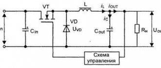
Switching power supplies
Schottky diodes are also used as rectifiers in switching power supplies. Low forward voltage and fast recovery time result in increased efficiency.
They can also be used in power supplies or circuits in products that have both internal battery and AC input or similar. However, in this case, the large reverse leakage current is a problem since any high impedance voltage sensing circuit (such as monitoring battery voltage or detecting the presence of an AC adapter) will see voltage from another power supply through the diode. a leak.
Sample-and-hold circuits
Schottky diodes can be used in diode bridge circuits. sample and keep the diagrams. Compared with a conventional pn junction based on diode bridges, Schottky diodes can have advantages. A forward biased Schottky diode has no minority carrier charge storage. This allows them to switch faster than conventional diodes, reducing the time from sample to hold stage. The absence of a minority carrier charge store also results in a lower retention step or sampling error, resulting in more accurate sampling at the output.[8]
Charge control
By effectively controlling the electric field, Schottky diodes can be used to precisely load or unload individual electrons in semiconductor nanostructures such as quantum wells or quantum dots. [9]
Usage
Semiconductor diode, a two-electrode electronic device based on a semiconductor (SC) crystal. The concept of "P. d." combines various devices with different principles of operation, having a variety of purposes. The classification system for semiconductor devices corresponds to the general classification system for semiconductor devices. The most common class of electrical transformer diodes includes: rectifier diodes, pulse diodes, zener diodes, and microwave diodes (including video detectors, mixing detectors, parametric detectors, amplifier and generator diodes, multipliers, and switching detectors). Among optoelectronic devices, photodiodes, light-emitting diodes, and PP quantum generators are distinguished.
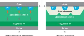
The most numerous are PDs, the action of which is based on the use of the properties of the electron-hole transition (p-n junction). If a voltage is applied to the p-n junction of the diode (Fig. 1) in the forward direction (the so-called forward bias), i.e., a positive potential is applied to its p-region, then the potential barrier corresponding to the junction decreases and begins intense injection of holes from the p-region into the n-region and electrons from the n-region into the p-region - a large forward current flows (Fig. 2). If a voltage is applied in the opposite direction (reverse bias), the potential barrier rises and only a very small minority carrier current flows through the pn junction (reverse current). In Fig. Figure 3 shows an equivalent circuit of such a P.D.
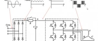
The operation of rectifier (power) diodes is based on the sharp asymmetry of the current-voltage characteristic (VC). For rectifier devices and other high-current electrical circuits, rectifier power supply units are produced that have a permissible rectified current Iv of up to 300 A and a maximum permissible reverse voltage U*rev from 20-30 V to 1-2 kV. Pds of similar application for low-current circuits have Iв < 0.1 a and are called universal.
At voltages exceeding U*o6p, the current increases sharply, and an irreversible (thermal) breakdown of the p-n junction occurs, leading to the failure of the p-n junction. In order to increase U*rev to several tens of kV, rectifier columns are used, in which several identical rectifier P.D. are connected in series and mounted in a common plastic housing. The inertia of rectifier diodes, due to the fact that the lifetime of the injected holes is > 10-5-10-4 sec, limits the frequency limit of their use (usually to the frequency range 50-2000 Hz). The use of special technological methods (mainly the doping of germanium and silicon with gold) made it possible to reduce the switching time to 10–7–10–10 sec and to create high-speed pulsed pulse generators, which are used, along with diode matrices, mainly in low-current signal circuits of computers.
It will be interesting What are ultraviolet LEDs?
Testing and interchangeability
Schottky rectifiers can be tested in the same way as conventional semiconductors, since they have similar characteristics. You need to ring it in both directions with a multimeter - it should show itself in the same way as a regular diode: anode-cathode, and there should be no leaks. If it shows even a slight resistance - 2-10 kilo-ohms, this is already a reason for suspicion.
Checking a Schottky diode with a multimeter
A diode with a common anode or cathode can be tested like two ordinary semiconductors connected together. For example, if the anode is common, then it will be one leg out of three. We place one tester probe on the anode, the other legs are different diodes, and another probe is placed on them.
Can it be replaced with another type? In some cases, Schottky diodes are replaced with ordinary germanium diodes. For example, D305 at a current of 10 amperes gave a drop of only 0.3 volts, and at currents of 2–3 amperes they can generally be installed without radiators. But the main purpose of the Schottky installation is not a small drop, but a low capacity, so replacement will not always be possible.
As we see, electronics does not stand still, and further applications of high-speed devices will only increase, making it possible to develop new, more complex systems.
Classification
Semiconductor diodes produced by industry, according to their purpose, can be divided into the following main groups:
- power,
- reference (zener diodes),
- photodiodes,
- impulse,
- high frequency,
- parametric.
Tunnel diodes are of particular interest. The marking of semiconductor diodes, the production of which was mastered after 1965, is determined by four elements. The first element of the designation is a letter that indicates the material of the semiconductor used: G - germanium; K - silicon; A - gallium arsenide. If the first element of the designation is a number (1 instead of G, 2 instead of K and 3 instead of A), then this indicates that the devices can operate at elevated temperatures (for example, devices with a silicon base, designated by the number 2, can operate at temperatures up to 120 ° WITH).
The second element of the marking is a letter that determines the purpose of the device: A - ultra-high-frequency diodes; D - universal rectifier, pulse diodes; B - rectifier columns (series connection of a number of diodes); C - zener diodes; I - tunnel diodes; F—photodiodes, etc. The third marking element (number) characterizes the electrical properties of the device. Rectifier low-frequency diodes are designated by numbers from 101 to 399, universal - from 401 to 499, pulsed - from 501 to 599, amplifying tunnel diodes - from 101 to 199, generator tunnel diodes - from 201 to 299, switching tunnel diodes - from 301 to 399 , Zener diodes - from 101 to 999.
The fourth marking element (letter) determines the type of device from a given group of devices. For example, 1D505B is a germanium pulse diode, a type B type, or 3I302B is a gallium arsenide tunnel diode, a type B type. Semiconductor diodes, the development of which was completed before 1965, are designated by three elements: the first element is the letter D; the second element is a number indicating the frequency ranges and the source material from which the diode is made; the third element determines the type of device.
Zener diodes (reference diodes) are semiconductor diodes designed to stabilize DC voltage. To stabilize the voltage in zener diodes, the reverse branch of the current-voltage characteristic in the region of electrical breakdown is used; for this they are turned on in the opposite direction. When the current flowing through the zener diode changes from the value Istmin to Istmax, the voltage across it almost does not change.
Semiconductor diode.
Zener diodes stabilize voltage from 3.5 V, and to stabilize lower voltages, stabistors are used. Stabistors use the direct branch of the current-voltage characteristic, so they are switched on in the forward direction. A pulsed diode is a diode that is designed to operate in pulsed circuits. In the forward direction, a pulsed diode conducts electricity well. When such a diode is turned on in reverse, the reverse current in it increases sharply, and after a short period of time disappears. This produces an electrical impulse.
Application of Schottky diodes
Schottky diodes are widely used. They can be found wherever a minimum forward voltage drop is required, as well as in RF circuits. Most often they can be seen in computer power supplies, as well as in switching voltage stabilizers.
These diodes have also found application in solar panels, since solar panels generate electric current only during daylight hours. To prevent the reverse process of current consumption from batteries in the dark, Schottky diodes are installed in the panels
Schottky in solar panels
In computer technology, you can most often see two diodes in one housing.
When writing this article, material from this video was used
Forward and reverse diode voltage.
The voltage at which the diode opens and direct current flows through it is called forward
(Upr), and the voltage of reverse polarity, at which the diode closes and reverse current flows through it, is called reverse
(Urev).
At forward voltage ( Upr
) the diode resistance does not exceed several tens of ohms, but with reverse voltage ( Urev
) resistance increases to several tens, hundreds and even thousands of kilo-ohms. This is not difficult to verify if you measure the reverse resistance of the diode with an ohmmeter.
Resistance pn
diode transition value is not constant and depends on the forward voltage ( Upr
), which is fed to the diode.
The greater
this voltage, the
less
the p-n
has , the
greater
the forward current
Ipr
flows through the diode.
In the closed state drops
, therefore, the reverse current passing through it
is small
, and the resistance of
the p-n
junction
is high
.
For example. If you connect a diode to an alternating current circuit, it will open at positive
half-cycles on the anode, freely passing direct current
(Ipr), and close at
negative
half-cycles at the anode, almost without passing a current in the opposite direction -
reverse current
(Irev).
These properties of diodes are used to convert alternating current into direct current
, and such diodes are called
rectifying
.
Reverse leakage current
But since Schottky diodes are so cool, why not use them everywhere? Why do we still use simple diodes?
If we connect the diode in the opposite direction, it will block the passage of electric current. This is true, but not entirely. Very little current will still flow through the diode. In some cases this is not taken into account. This small current is called reverse leakage current . In English it sounds like reverse leakage current .
It is very small, but it exists.
Let's do a simple experiment. Let's take a laboratory power supply, set it to 19 V and apply this voltage to the diode in the opposite direction
We measure the leakage current
diode reverse leakage current
As you can see, its value is 0.1 µA.
Let's now repeat the same experiment with a Schottky diode
Schottky diode reverse leakage current
Wow, almost 20 µA already! Well, yes, in some cases these are mere pennies and can be ignored. But there are circuits where such a small current is still unacceptable. For example, in peak detector circuits
peak detector circuit
In this case, these 20 µA will be quite significant.
But there is also another stumbling block. As the temperature increases, the reverse leakage current increases significantly!
dependence of the reverse leakage current on the body temperature of the Schottky diode
Therefore, you cannot use Schottky everywhere in the circuits.
But that's not all. The reverse voltage for Schottky diodes is several times less than for simple rectifier diodes. This can also be seen from the datasheet. If the reverse voltage is 1000V for the 1N4007 diode
Then for a 1N5817 Schottky diode this reverse voltage will already be only 20 V
Therefore, if this voltage exceeds the value described in the datasheet, we will end up with:
Thyristor device
Fixing the steady state of the device is possible due to the presence of a number of features in the internal structure of the device. You can see this in the diagram below:
On this structure, it becomes obvious that the thyristor is presented in the form of 2 simple electronic transistors, which are not similar in structure, but are interconnected. In addition, the following three units play a key role in the composition of a semiconductor electrical device:
- Cathode;
- Anode;
- Control electrode.
Due to the fact that the thyristor has four series-connected diodes, its transition layer has the following shape: (p) - (p) - (p) - (p). This fact explains the capacity I, which flows only in a single direction: from plus to minus.
Speaking and describing the appearance of thyristors, it must be said that they are made from different cases, so the option with simple heat removal is excluded, however, due to the presence of a massive metal case, they are able to withstand high currents.
Designation
SS14 Schottky diode in DO-214 AC (SMA) package (surface mount version 1N5819)[10]
Commonly found Schottky diodes include 1N58xx series rectifiers such as 1N581x (1) and 1N582x (3A) through-pieces,[6][11 ] and surface mount parts SS1x (1 A) and SS3x (3 A).[10][12] Schottky rectifiers are available in a variety of surface mount housing styles.[13][14]
Small signal Schottky diodes such as 1N5711,[7] 1N6263, g.[15] 1SS106,[16] 1SS108,[17] and BAT41–43, 45–49 series[18] are widely used in high frequency applications as detectors, mixers and nonlinear elements and have replaced germanium diodes.[19] They are also suitable for electrostatic discharge (ESD) protection of sensitive devices such as III-V semiconductor devices, laser diodes and, to a lesser extent, bare-line CMOS circuitry.
Metal-to-semiconductor Schottky junctions are introduced in the successors to the 7400 TTL family of logic devices, the 74S, 74LS, and 74ALS, where they are used as Baker clamps in parallel with the collector-to-base junctions of bipolar transistors to prevent them from saturating, thereby significantly reducing turn-off delays.