03/10/2016 One comment Category: Automation in everyday life, Basics of automation
In everyday life, we often come across switches. These are all kinds of switches, buttons, toggle switches - they allow you to control devices discretely, in other words, turn them on and off. A regular switch consists of two contacts that can be used to close or open an electrical circuit. Discrete control of various devices in automatic mode implies the ability to turn them on and off without human intervention. It is for this purpose that an electromagnetic relay is intended, and that is why not a single automatic control system can do without it.
An electromagnetic relay is a device that has a group of contacts that change their state to the opposite when a control voltage is applied.
Rice. 1. Electromagnetic relay
In simple words, a relay is a switch that is turned off not manually by a person, but electrically, by applying a control signal. To make it completely clear, let’s consider the principle of operation of an electromagnetic relay.
Relay operating principle
A relay consists of a coil, an armature and a group of contacts.
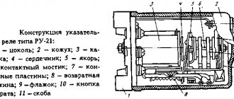
Rice. 2
1 – relay contact conductors, 2 – relay contacts, 3 – armature, 4 – core, 5 – coil
The principle of operation of the relay is extremely simple. If you apply a control voltage to the coil, a magnetic field will arise in it and attract the armature, which in turn will close the contacts. In Fig. Figure 2 shows a relay with one group of contacts, but in the general case there can be many groups of contacts. When a magnetic field appears in the coil, they all change their position to the opposite. Yes Yes! Exactly the opposite. This means that initially they can be not only open, but also closed.
DRL connection diagram without relay
This is the simplest DRL connection diagram, but also the most incorrect. I'll describe it a little. With this connection scheme, you supply voltage to the DRLs from the main power circuit of the car. The main power circuit is activated when the key is turned in the ignition switch. Obviously, your DRLs will always work as long as the key is turned in the ignition, no matter what lighting you use. You have no way to turn off the DRLs until you remove the key from the ignition.
As you already know, the use of DRLs in conjunction with other lighting devices is prohibited. I do not recommend connecting DRLs using this scheme.
Normally closed and normally open contact
There are two main types of relay contacts: normally closed (NC) and normally open (NO) . The names reflect the "normal" state of the contacts when there is NO voltage across the relay coil. Normally closed contacts are closed in the normal state, and normally open contacts are open.
Another type of contact is changeover contact. They can be called neither normally closed nor normally open, since they have both contacts. When a relay is switched, such a contact opens one circuit and closes another. This will become clearer when we look at their graphic designation in the diagram.
Designation
On electrical diagrams, relays are designated as several separate elements:
- coil
- NC contact
- BUT contact
- Reversible
The conditional division into different elements is introduced solely for convenience. This allows you to place the coil and contacts in different parts of the circuit to make it more compact and readable. In this case, all elements of one relay are designated by the same letter code, because structurally it is one element.
Also, for convenience, some relay elements can be shown together in the diagram. For example, a group of normally open contacts can be designated this way:
Principle of operation
Contact 30 is a common contact, contact 87A is a normally closed contact, contact 87 is a normally open contact.
Wiring diagram for a five-pin relay The wiring diagram for a five-pin relay is suitable for creating an alarm. Each contact has its own designation.
This seems complicated, but let's look at an example and everything will become clear.
Signal inversion circuits can be used to invert door or trunk switch signals when connecting to an alarm system or in other cases. We connect to low-current transistor alarm outputs.
Related article: At what depth are electrical cables laid?
Site search
After applying a control signal to the relay, the first output will become open and the second will become closed. As a result, on pin 30 we have the polarity that is on pin
Before studying the wiring diagram for any automotive device via a relay, you need to know what a relay is in general and how it works. Let's consider connecting fog lights. I want to power it up like the DRLs, that is, when I start them they light up, when I turn them off they don’t light up. If we briefly describe this figure, we get the following: DRLs should be installed at a height of to mm; The distance between adjacent edges of the DRLs must be at least mm; The distance from the outer side surface of the car to the nearby edge of the DRL should be no more than mm. After the voltage supply is stopped, the winding current disappears and the core is demagnetized.
Relay Mechanisms
Now, if you try to start the car with the security switched on, contact 30 will open with contact 87A and will not allow the engine to start. Stories from our readers “Fucking basin!!! Signal inversion circuits can be used to invert door or trunk switch signals when connecting to an alarm system or in other cases. Knowing the legislation and rules for using DRLs, we are ready to move on to the practice of connecting them. For a voltage relay Schematic diagram of a home network using voltage relays, RCDs and circuit breakers. The connection diagram for a voltage relay involves mounting the device on a DIN rail in the switchboard.
Let's cut this wire. Imported relays under the Saturn and San Hold brands have proven themselves to be the most reliable and commercially available; relays from other manufacturers are also used. Maximum current in the power circuit: 30A. Structurally, the standard regulator has the form of a bag for mounting on a DIN rail. To connect according to this scheme, you will need a 4-pin relay. RELAY. Easy connection
Examples
Example 1. Let’s draw a diagram that implements the following algorithm: if the pump is on, the green light is on, and if it’s off, the red light is on.
At the moment when the pump turns on, the limit switch (normally open contact), which we introduced into our circuit, closes inside it. At the same time, voltage “comes” to the coil of relay K1 - the relay is activated, opening the NC contact K1.1, and the red light goes out. At the same time, when the contact inside the pump closes, the green light comes on.
Example 2. Let's implement example 1 using a relay changeover contact.
In this circuit, relay contact K1.1 is a changeover contact. When the relay is in the “normal” state, the red lamp is on. When triggered, relay K1.1 changes its state and the green lamp lights up.
Tags: relay, relay logic
DRL connection diagram via 4-pin relay
To connect the DRL according to this scheme, you, as in the previous case, will need a 4-pin relay. Moreover, the connection diagram is absolutely identical to the previous case, only instead of the control signal from the oil pressure sensor, we will use a button in the car interior. Your DRLs will only turn on when you press a button in the cabin.
You can add a little automation to this scheme. In order for the DRLs to go off when the engine is stopped, you can send a signal to the button from the fuel pump, or from the same oil pressure sensor. This scheme already has the right to life, because you can control the DRL operation depending on your driving conditions.
The only downside is that you need to manually turn off the DRLs (press a button in the cabin) when you turn on the low beam headlights, and also manually turn on the DRLs when driving during daylight hours.
2nd connection option (restoring the operation of the seat belt warning device)
I traveled like this for a week and realized that I was somehow uncomfortable and missing something. It turned out that the same light went out on the panel and the squeak of the belt buzzer disappeared. And I decided to restore it. You will need a 4-pin automotive relay (5-pin is also suitable), the diagram is as follows:
Terminals 30 and 87 of the lower relay go to the belt warning chip on the ECU side. Looks like that.
Now the recorder turns on and off, and the seat belt warning light works normally.
Selection of solid-state relays, protection and operating features
A conventional relay and contactor can withstand short-term overloads of up to 150 and even 200% of the nominal without any problems. Especially if you do not switch the load with such a current, but increase the current after closing, and lower it before opening.
Ordinary contacts can withstand short-term short-circuit current if the protection with the correct current setting is activated. You just might have to clean the contacts later.
Solid-state relays suffer more from overloads; within half a period they deteriorate irrevocably, and the contacts cannot be cleaned later due to the lack of them.
If when choosing a contactor it is enough to select a margin of 10-20% and protect it with a conventional automatic machine, then with solid-state devices everything is more complicated.
Therefore, for solid-state relays, it is recommended for active loads (lamps, heating elements) to have a rated current reserve of 2-4 times. When starting asynchronous motors, due to the large starting current, the current reserve must be increased to 6-10 times.
That is, the three-phase solid state Fotek TSR-40AA-H 40A, shown in the photo just above, is unlikely to work at its 40 amperes. The motor power that can be switched in this case is from 2.2 kW to 5 kW. Moreover, a 5 kW engine (this is about 10A) must be started at idle, with a minimum starting torque, and a load can be applied to it after start-up and acceleration.
By the way, solid-state relays can behave inappropriately with an inductive load; I had problems. In the case of highly inductive loads (transformers, coils with magnetic cores, electric bells, etc.), it is necessary to connect an RC circuit (snubber circuit of a series resistor and capacitor) in parallel with the load to reduce the influence of back-EMF. In addition, this circuit reduces the overall load inductance, i.e. makes her more active. And TTP is easier to work with.
Advantages and disadvantages
The main types of relays have many advantages over semiconductor switches, such as:
- relatively low cost (due to inexpensive components);
- there is strong insulation between the coil and the contact group;
- are not subject to the harmful effects of overvoltage, lightning interference, or switching of powerful electrical installations;
- there is control of lines with a load of up to 0.4 kV (with a small volume of the device).
An additional advantage is that there is no cooling problem and it is harmless to the atmosphere. For example, when a circuit with a current of 10 A is applied to the relay, less than 0.5 W is distributed across the coil. In comparison with electronic analogues, this value is higher than 15 W.
Disadvantages of a pulse relay:
- wear, as well as problems with switching inductive loads and high voltages (if the current is constant);
- when the circuit is turned on and off, radio interference occurs, so shielding is required;
- relatively long response time.
A serious disadvantage can be considered continuous wear during switching (deformation of springs, oxidation of contacts, for example).
However, it is worth clarifying that when using electronic relays, there are such advantages as: safety, good connection speed, availability on the market, silent operation, advanced functionality. And among the disadvantages: overheating when switching high currents, disruption of operation during power failures, resistance in the closed position, etc.
Watch this video on YouTube
Watch this video on YouTube
However, electronic relays are developing quite steadily and quickly. They are popular due to their functionality, which can be expanded relatively easily.
What does the marking tell you?
The marking of contactors contains a complete set of data on the purpose and design features, including information on climatic design.
Explanation of the TKE520DG model: a device with winding withstand up to 30 V, and contacts up to 5 A, there are two normally open contacts, the design of the device provides for long-term operation, it is sealed
Let us consider in detail the structure of the symbol using the example of PE41(N) (*)(*)(*)(*)(*)/(*)(*)(*)(*)5:
- REP - electromagnetic intermediate relay.
- 37 (N) – development number.
- (*) - designation of the type of current in the circuit of the switching winding: 1 - direct current; 2 - alternating current.
- (*) — type of deceleration: 1 — decelerated when turned on; 2 - slow when turned off.
- (*) - value based on the number of windings;
- (*)(*) — numerical value of the normally open and closed contacts;
- (*)(*) - voltage or current of power winding: constant (D) and alternating (A);
- (*)(*) - designation of the electrical force of the holding windings;
- (*) - type and technology of connecting rear conductor lines: 1 – with lamellas for soldering; 2 – installation with screw fixation; 3 — fastening with terminals to the connector block.
- (*)5 - climatic design and placement category according to GOST: UH - moderately cold; B - all-climate.
When choosing the required model of a switching device, not only its electrical parameters are taken into account, but also the environment in which it will operate. The selection of a contactor is made based on the required characteristics: supply power (V), power consumption (W), switched current (A), groups of contacts, operating time (s), dimensions
The selection of a contactor is made based on the required characteristics: supply power (V), power consumption (W), switched current (A), groups of contacts, operating time (s), dimensions
Despite the high quality of the switch, the main drawback lies in the contact system. It is assumed that a pure connected group can only exist under sealed vacuum conditions. If the main negative factor is exposed - contact with air - an oxide film begins to form on them.