The resistance of a cable's insulating layer is one of the most important parameters of its performance. If you bought a cable and it was stored in a warehouse for some time, do not think that its insulation will be the same as when you bought it. Insulation can deteriorate both under unsatisfactory storage conditions and during operation and installation. In order to identify all possible problems, the cable insulation is checked with a megohmmeter.
Causes of poor cable insulation
There are several factors affecting the insulating properties of cables:
- ⚡
atmospheric conditions In winter, insulation may suddenly improve as... the moisture inside will simply turn into ice. - ⚡
cable laying process
Careless movements during installation can cause a break or damage the shell. - ⚡
physical wear and tear over time - ⚡
exposure to aggressive environment -
⚡
excessive voltage during operation
In order to identify an insulation problem in time, you will need a special device - a megohmmeter. These devices are of the old type (mechanical, where you need to rotate the handle):
and a new model - electronic:
Let's consider the operation of these devices.
Safety regulations
Checking the cable insulation with a megohmmeter is carried out only with the equipment disconnected and de-energized.
The megaohmmeter is capable of producing high voltage (certain types up to 5000 Volts), so when working with it, strictly follow the following rules:
- ⚡
Personnel with the 3rd electrical safety group have the right to work with the device - ⚡
When testing, remove all strangers from the cable being tested - ⚡
Before operating the device, carefully inspect its housing, wires and test leads. They should not be chipped or damaged; - ⚡
It is recommended to measure cable insulation at positive temperatures - ⚡
do not touch the wires of the device when taking measurements
Preparatory work
The cable under test must be prepared before testing.
For this:
- ⚡
check that there is no voltage on the cable cores - ⚡
on long cables there may be induced or residual voltage. Therefore, before each measurement, using a separate piece of wire or a portable grounding device, wearing dielectric gloves, it is necessary to touch the core and the grounded housing or grounding loop to remove this charge; - ⚡
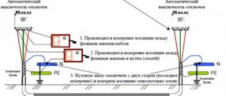
disconnect the cable from the connected equipment. This must be done so that when checking the cable insulation with a megohmmeter, only the cable itself is involved in the test, without the equipment or machines to which it is connected. Disconnection must be done on both sides of the cable. Sometimes this is not done to speed up work. First, a measurement is taken, and if it shows a negative result, then only after that the wires are pulled back.
Test methods and interpretation of results
Short-term or spot measurement
This is the simplest method. It involves applying test voltage for a short time (30 or 60 seconds) and recording the insulation resistance value at this moment. As stated above, this direct measurement of insulation resistance is significantly influenced by temperature and humidity, so the measurement should be standardized at a reference temperature and the humidity level should be recorded for comparison with previous measurements. Using this method, you can analyze the quality of the insulation by comparing the current measured value with the results of several previous tests. Over time, this will provide more reliable information about the insulation performance of the installation or equipment being tested compared to a single test.
If the measurement conditions remain identical (same test voltage, same measurement time, etc.), then with periodic measurements, a clear assessment of the insulation condition can be obtained by monitoring and interpreting any changes. After recording the absolute value, it is necessary to analyze the change over time. Thus, a measurement showing a relatively low insulation value that is nonetheless stable over time should theoretically be less of a concern than a significant decrease in insulation resistance over time, even if the insulation resistance is higher than the recommended minimum value. In general, any sudden drop in insulation resistance indicates a problem that needs to be investigated.
The graph below shows an example of insulation resistance readings for an electric motor.
At point A, the insulation resistance decreases due to aging and dust accumulation.
A sharp drop at point B indicates insulation failure.
At point C, the fault has been cleared (the motor winding has been rewound) and the insulation resistance has returned to a higher value that remains stable over time, indicating good insulation condition.
Test methods based on the influence of test voltage application time (PI and DAR)
These methods involve sequentially measuring insulation resistance values at specified times. They have the advantage of not being particularly affected by temperature, so they can be used without correction of the results, unless the test equipment is exposed to significant temperature fluctuations during the test.
These methods are ideal for preventive maintenance of rotating machines and for insulation monitoring.
If the insulating material is in good condition, the leakage current or conduction current will be low, and the initial measurement will be greatly influenced by the capacitance charging and dielectric absorption currents. As the test voltage is applied, the measured insulation resistance value increases over time as these interference currents decrease. The stabilization time required to measure insulation in good condition depends on the type of insulating material.
If the insulating material is in poor condition (damaged, dirty and wet), the leakage current will be constant and very high, often exceeding the capacitance charging and dielectric absorption currents. In such cases, the insulation resistance measurement very quickly becomes constant and stabilizes at a high voltage value.
Studying the change in the insulation resistance value depending on the time of application of the test voltage makes it possible to assess the quality of the insulation. This method allows conclusions to be drawn even if no insulation measurement log is kept. However, it is recommended that the results of periodic measurements performed in the context of a preventive maintenance program be recorded.
Polarization Index (PI)
Using this method, two readings are taken at 1 minute and 10 minutes, respectively. The ratio (without dimensions) of the 10-minute insulation resistance value to the 1-minute value is called the polarization index (PI). This indicator can be used to assess the quality of insulation.
The polarization index measurement method is ideal for testing solid insulation circuits. This method is not recommended for use on equipment such as oil-immersed transformers as it produces poor results even if the insulation is in good condition.
IEEE Recommendation 43-2000, Recommended Test Methods for Insulation Resistance of Rotating Machines, specifies a minimum polarization index (PI) value of 2.0 for AC and DC rotating machines in temperature classes B, F, and H. In general, a PI value greater than 4 is a sign of excellent insulation, while a value below 2 indicates a potential problem.
PI = R (10-minute insulation measurement) / R (1-minute insulation measurement)
The results are interpreted as follows:
| PI value (norm) | Insulation state |
| Problematic | |
| From 2 to 4 | good |
| > 4 | Excellent |
Dielectric Absorption Rate (DAR)
For installations or equipment containing insulating materials in which the absorption current decreases quickly, a measurement at 30 seconds and 60 seconds may be sufficient to assess the condition of the insulation. The DAR coefficient is determined as follows:
DAR = R (60 second insulation measurement) / R (30 second insulation measurement)
The results are interpreted as follows:
| DAR value (norm) | Insulation state |
| Unsatisfactory | |
| Normal | |
| >1,6 | Excellent |
Method based on the effect of changing test voltage (step voltage testing)
The presence of contamination (dust, dirt, etc.) or moisture on the insulation surface is usually clearly detected by time-dependent resistance measurements (PI, DAR, etc.). However, this type of testing, conducted using a low voltage relative to the dielectric voltage of the insulating material being tested, can sometimes miss signs of insulation aging or mechanical damage. A significant increase in the applied test voltage can, in turn, cause damage at these weak points, which will lead to a significant decrease in the measured insulation resistance value.
To be effective, the ratio between voltage steps must be 1 to 5, and each step must be the same in time (typically 1 to 10 minutes), while remaining below the classic dielectric test voltage (2Un + 1000 V). The results obtained with this method are completely independent of the type of insulation and temperature, because it is not based on the internal value of the insulator being measured, but on the effective reduction of the value obtained after the same time for two different test voltages.
A decrease in insulation resistance value of 25% or more between the first and second measurement steps is evidence of insulation deterioration, which is usually associated with the presence of contamination.
Dielectric Dissipation (DD) Test Method
The dielectric leakage (DD) test, also known as reabsorption current measurement, is performed by measuring the dielectric leakage current on the equipment under test.
Since all three current components (capacitance charging current, polarization current, and leakage current) are present during a standard insulation test, the determination of polarization or absorption current may be influenced by the presence of leakage current. Instead of attempting to measure polarization current during insulation testing, dielectric dissipation (DD) testing measures depolarization current and capacitance discharge current after insulation testing.
The measurement principle is as follows. First, the equipment under test is charged for a time sufficient to reach a steady state (capacitance charging and polarization is complete and the only current flowing is leakage current). The equipment is then discharged through a resistor inside the megger and the current flowing is measured. This current consists of the capacitance charging current and the reabsorption current, which together give the total dissipation current in the dielectric. This current is measured after a standard time of one minute. The electric current depends on the total capacitance and the final test voltage. The DD value is calculated using the formula:
DD = Current after 1 minute / (Test Voltage x Capacitance)
The DD test identifies excess discharge currents when one of the layers of multi-layer insulation is damaged or contaminated. In spot tests or PI and DAR tests, such a defect may be missed. For a given voltage and capacitance, the discharge current will be higher if one of the insulation layers is damaged. The time constant of this individual layer will no longer be the same as the other layers, resulting in a higher current value compared to undamaged insulation. Homogeneous insulation will have a DD value close to zero, and acceptable multi-layer insulation will have a DD value of up to 2. The table below indicates the condition depending on the DD value obtained.
| DD (norms) | State |
| > 7 | Very bad |
| From 4 to 7 | Bad |
| From 2 to 4 | Doubtful |
| Normal |
Note: This measurement method is temperature dependent, so each test attempt must be performed at a standard temperature, or at least the temperature must be recorded along with the test result.
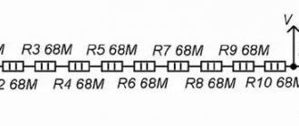
High Resistance Insulation Testing: Using Jack G on a Megger
When measuring insulation resistance values (above 1 GOhm), the accuracy of the measurements can be affected by leakage currents flowing along the surface of the insulating material through moisture and contaminants present on it. The resistance value is no longer high and therefore negligible compared to the resistance of the insulation being evaluated. To eliminate surface current leakage that reduces the accuracy of insulation measurement, some megohmmeters have a third socket designated G (Guard). This socket bypasses the measurement circuit and reintroduces surface current to one of the test points, bypassing the measurement circuit (see figure below).
When choosing the first circuit, without using socket G, the leakage current i and the unwanted surface current I1 are simultaneously measured, so the insulation resistance is measured incorrectly.
However, when choosing the second scheme, only the leakage current i is measured. Connection to socket G allows the surface current I1 to be diverted, so the insulation resistance measurement is carried out correctly.
The G socket must be connected to a surface that carries surface currents and is not an insulator such as cable or transformer insulation. Knowing the possible paths for test currents to flow through the element under test is critical to selecting the connection location to socket G.
Checking the megohmmeter
Before checking the cable insulation with a megohmmeter, it is necessary to test the operation of the device itself. Here's how to do it on the M4100 megohmmeter. The device has 2 scales: the upper one for measurements in megaohms and the lower one for measurements in kiloohms.
To work in megaohms:
- ⚡
connect the ends of the probe wires to the two left terminals. The probes must be open; - ⚡
rotate the knob and watch the arrow readings. If the device is working properly, it will tend to the left - towards infinity; - ⚡
close the probes together. When you rotate the knob, the arrow should deflect to the right to zero.
To work in kilo-ohms:
- ⚡
Place a jumper between the 2 left terminals and connect one of the ends there. The second end is connected to the rightmost terminal. The probes are open; - ⚡
Rotate the knob and watch the readings. When the device is working properly, the arrow deviates as far as possible to the right; - ⚡
After closing the probes and rotating the knob, the arrow will tend to zero on the lower scale (i.e. to the left).
//youtu.be/jXYvBHUKvCo
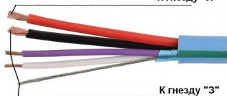
Line connection
The standard package includes three probes with different characteristics and structures. One of them has two tips and is designed to combat leakage currents. On the top side of the device there are three sockets for connecting probes. Each of them is characterized by a corresponding letter marking:
- Z - for connecting protection grounding.
- L is the line that is being measured.
- E - screen (intended to eliminate leakage currents).
You may be interested in: Causes and consequences of a short circuit
There are no other options, except for cases with shielded wiring. However, in private buildings such methods are not used, since the installation of cables with a screen is practically useless here. However, if you have this type of cable, you need to minimize the risk of leakage currents by using a probe with a split end. The wires of the shielding braid must be twisted into a bundle, adding to the general bundle of wires.
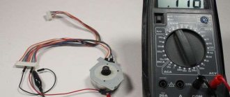
Working with megaohmmeter M4100
//youtu.be/VThv9RXyEzY
- First of all, check that there is no voltage on the cable
- ground all conductors
- place the device on a flat surface
- When measuring conductor insulation to ground, one of the probes is connected to the wire, the other to the armor or grounding device. Then remove the grounding only from the core being measured;
- Rotate the knob evenly for 60 seconds. Rotation speed is two revolutions per second. At 60 seconds, note the readings of the device;
- After each measurement, remove the residual charge from the core and wires of the megohmmeter by touching them to ground.
It is enough to test household networks and home wiring with a voltage of 500 Volts. The minimum value that a cable insulation test with a megohmmeter should show in this case is 0.5 mOhm.
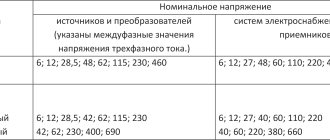
In industrial power networks, cables are tested with 2500 Volt megaohmmeters. The insulation resistance must be at least 10 mOhm.
The principle of measuring insulation resistance and the factors influencing it
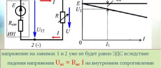
Insulation resistance measurement is based on Ohm's law. By applying a known DC voltage at a level lower than the dielectric test voltage and then measuring the current value, it is very easy to measure the resistance value. In principle, the value of the insulation resistance is very large, but not infinite, therefore, when measuring a small flowing current, the megohmmeter indicates the value of the insulation resistance in kOhm, MOhm, GOhm and even in TOhm (on some models). This resistance characterizes the quality of the insulation between two conductors and can indicate the risk of leakage current.
The value of the insulation resistance, and therefore the amount of current that flows when DC voltage is applied to the circuit under test, is influenced by a number of factors. Such factors include, for example, temperature or humidity, which can significantly affect the measurement results. First, let's analyze the nature of the currents flowing during an insulation measurement, using the hypothesis that these factors do not affect the measurement being made.
The total current flowing in the insulating material is the sum of three components:
- Capacity. To charge the capacitance of the insulation under test, a capacitor charging current is required. This is a transient current that starts at a relatively high value and drops exponentially to a value close to zero as the circuit under test becomes electrically charged. After a few seconds or tenths of a second, this current becomes insignificant compared to the measured current.
- Absorption. Absorption current corresponding to the additional energy required to reorient the molecules of the insulating material under the influence of an applied electric field. This current drops much more slowly than the capacitance charging current; sometimes it takes several minutes to reach a value close to zero.
- Leakage current or conduction current. This current characterizes the quality of the insulation and does not change over time.
The graph below shows these three currents as a function of time. The time scale is arbitrary and may vary depending on the insulation being tested.
To ensure proper test results on very large motors or very long cables, minimizing capacitive and absorption currents can take 30 to 40 minutes.
When a constant voltage is applied to a circuit, the total current flowing in the insulator under test varies as a function of time. This implies a significant change in insulation resistance.
Before looking in detail at the various measurement methods, it would be useful to take another look at the factors that influence insulation resistance measurement.
Effect of temperature
Temperature causes a quasi-exponential change in the insulation resistance value. In the context of a preventive maintenance program, measurements should be made under uniform temperature conditions or, if this is not possible, should be corrected relative to a reference temperature. For example, a 10°C increase in temperature reduces the insulation resistance by approximately half, while a 10°C decrease in temperature doubles the insulation resistance value.
The level of humidity affects the insulation according to the degree of contamination of its surface. Never measure insulation resistance when the temperature is below the dew point.