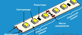
I’ll immediately make a reservation that the article will be devoted not only to how an LED is indicated on the diagram, but also to diodes as such, due to the fact that they are the progenitors of LEDs.
Let's turn to physics: a diode can be translated as “two-electrode”. Since ancient times, electronics were built on electric vacuum devices, and it was from there that television lamps were called diodes, triodes, pentodes, etc.
In general, semiconductor diodes were invented in the early 20th century and were used to “distinguish” the detection of radio signals. The name of the diodes is based on the number of electrodes (device legs) - diodes (two), triode (three), etc.
—> —>
The main property of any diode is its conductivity characteristic. The designation of the diode on the diagram allows you to determine the direction of the current. The movement of the current will always coincide with the arrow on the Symbol. UGO is an element (icon) that denotes a diode in the diagram. Let's consider a number of the most common types of semiconductors on the circuit from other similar elements.
Introduction
But let's start a little from afar... Every young specialist who comes to design begins either by folding drawings, or by reading regulatory documentation, or by drawing “this” according to this example. In general, normative literature is studied in the course of work and design.
It is impossible to read all the normative literature related to your specialty or even a narrower specialization. Moreover, GOST, SNiP and other standards are periodically updated. And each designer has to monitor changes and new requirements of regulatory documents, changes in the lines of electrical equipment manufacturers, and constantly maintain their qualifications at the proper level.
Remember Lewis Carroll in Alice in Wonderland?
This is not my way of whining about “how hard the life of a designer is” or boasting “look, what an interesting job we have.” That's not what we're talking about now. Given such circumstances, designers adopt practical experience from more experienced colleagues; they simply know how to do many things correctly, but do not know why. They work according to the principle “That’s the way it is here.”
Sometimes these are quite basic things. You know how to do it right, but if they ask “Why is this?”, you won’t be able to answer right away, referring at least to the name of the regulatory document.
In this article, I decided to structure the information regarding symbols, sort everything out, and collect everything in one place.
Understanding LED Polarity and Why It's Important
LEDs are semiconductor devices that, when voltage is applied, allow current to flow in only one direction. They are low voltage components. They have the following characteristics:
- two contacts – positive and negative;
- Polarity is the ability to pass current in one direction.
The device operates on constant voltage. If it is turned on incorrectly, it may fail. Failure occurs due to the fact that if the polarity is not observed, the crystal experiences significant load for a long time and degrades.
On an electronic circuit, a light-emitting diode is graphically labeled as a conventional diode symbol placed in a circle with two arrows pointing outward. The arrows indicate the ability to emit light.
Graphic symbols in electrical diagrams
Regarding graphic symbols in electrical circuits, GOST 2.702-2011 refers to three other GOSTs:
- GOST 2.709-89 “ESKD. Conventional designations of wires and contact connections of electrical elements, equipment and sections of circuits in electrical circuits.”
- GOST 2.721-74 “ESKD. Conditional graphic designations in schemes. Designations for general use"
- GOST 2.755-87 “ESKD. Conventional graphic symbols in electrical diagrams. Switching and contact connection devices."
Conventional graphic symbols (UGO) of automatic circuit breakers, switches, contactors, thermal relays and other switching equipment that is used in single-line diagrams of electrical panels are defined in GOST 2.755-87.
However, there is no designation for RCDs and difavtomats in GOST. I think it will soon be reissued and the RCD designation will be added. In the meantime, each designer depicts an RCD according to his own taste, especially since GOST 2.702-2011 provides for this. It is enough to provide the UGO designation and its explanation in the explanations of the diagram.
In addition to GOST 2.755-87, to complete the circuit, you will need to use images from GOST 2.721-74 (mainly for secondary circuits).
All designations of switching devices are based on four basic images:
using nine functional features:
| Name | Image |
| 1. Contactor function | |
| 2. Switch function | |
| 3.Disconnector function | |
| 4. Switch-disconnector function | |
| 5. Automatic triggering | |
| 6. Travel or limit switch function | |
| 7. Self-return | |
| 8. No self-return | |
| 9. Arc suppression | |
| Note: The designations given in paragraphs. 1 - 4, 7 - 9, are placed on fixed contacts, and the designations in paragraphs. 5 and 6 - on moving contacts. |
Basic graphic symbols used in single-line diagrams of electrical panels:
| Name | Image |
| Circuit breaker (automatic) | |
| Load switch (switch) | |
| Contactor contact | |
| Thermal relay | |
| RCD | |
| Differential automatic | |
| Fuse | |
| Automatic switch for motor protection (circuit breaker with built-in thermal relay) | |
| Load switch with fuse (switch with fuse) | |
| Current transformer | |
| Voltage transformer | |
| Electric energy meter | |
| A frequency converter | |
| Normally closed contact of a push-button switch without self-reset with the control element opening and returning automatically | |
| Normally closed contact of a push-button switch without self-reset with opening and return of the control element by pressing the button a second time | |
| Normally closed contact of a push-button switch without self-reset with opening and return of the control element by pulling the button | |
| Normally closed contact of a push-button switch without self-reset with opening and returning of the control element via a separate drive (for example, pressing a reset button) | |
| Normally closed contact with delay when activated | |
| Normally closed contact with delay during return | |
| Normally closed contact with delay during operation and return | |
| Normally closed contact with delay when activated | |
| Normally closed contact with delay during return | |
| Normally closed contact with delay during operation and return | |
| Contactor coil, general designation for relay coil | |
| Impulse relay coil | |
| Photo relay coil | |
| Timing relay coil | |
| Motor drive | |
| Lighting lamp, light indication (light bulb) | |
| A heating element | |
| Plug connection (socket): socket pin | |
| Arrester | |
| Surge suppressor (SPD), varistor | |
| Dismountable connection (terminal) | |
| Ammeter | |
| Voltmeter | |
| Wattmeter | |
| Frequency meter |
The designations of wires and busbars in electrical panels are determined by GOST 2.721-74.
| Name | Image |
| Electrical communication line, wires, cables, buses, group communication line | |
| The protective conductor (PE) may be shown as a dashed line | |
| Graphic branching (merging) of group communication lines | |
| Crossing of electrical communication lines, group communication lines of electrically not connected wires, cables, tires, not electrically connected | |
| Electrical communication line with one branch | |
| Electrical communication line with two branches | |
| Bus (if it is necessary to graphically separate electrical communication lines from the image) | |
| Branch bus | |
| Buses graphically intersecting and not electrically connected | |
| Branches (tap-offs) from the bus |
Testing with a multimeter or battery
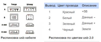
It's good if you have a multimeter at hand. Then the polarity of the LED will be determined in one minute. Having selected the ohmmeter mode (resistance measurement), it is easy to perform the following action. By applying the probes to the legs of the LED, the resistance is measured. The red wire should be connected to the positive, and the black wire to the negative.
When turned on correctly, the device will produce a value approximately equal to 1.7 kOhm, and a glow will be observed. When turned back on, the multimeter display will display an infinitely large value. If the test shows that the diode shows low resistance in both directions, then it is broken and should be discarded.
Some devices have a special mode. It is designed to check the polarity of the diode. Direct switching will be signaled by a backlit diode. This method is suitable for red and green semiconductors.
Blue and white LEDs only provide an indication at voltages greater than 3 volts, so the desired result cannot be achieved. To test them, you can use multimeters like DT830 or 831, which have a mode for determining the characteristics of transistors.
Using the PNP part, one lead of the LED is inserted into the collector socket, the second into the emitter hole. In case of direct connection, an indication will appear; inverse connection will not give a similar effect.
How to determine the polarity of an LED if you don’t have a multimeter at hand? You can resort to a regular battery or accumulator. For this you will need any other resistor. This is necessary to protect the LED from breakdown and failure. A series-connected resistor, the value of which should be approximately 600 Ohms, will limit the current in the circuit.
And a few more tips:
- If the polarity of the LED is known, it is no longer possible to apply reverse voltage to it. Otherwise, there is a risk of breakdown and failure. With proper use, the LED will serve well, since it is durable, and its housing is well protected from moisture and dust;
- Some types of LEDs are sensitive to static electricity (blue, violet, white, emerald). Therefore, they need to be protected from the influence of “statics”;
- When testing an LED with a multimeter, it is advisable to perform this action quickly; touching the terminals should be short-term in order to avoid breakdown of the diode and its failure.
Type of bulb and base
The LED lamps offered to customers differ in the shape and size of the bulb. These parameters are determined by specific values on the box.
Figure 2. Types of flasks
The most popular flask markings and their interpretation:
- A – traditional shape, reminiscent of a pear (similar to incandescent lamps);
- C – candle shape;
- R – resembles a mushroom;
- G – spherical flask;
- T – tubular design;
- P – spherical shape.
A socket is used to connect the device to the lighting system. The most popular are traditional sockets marked “E”. They provide a connection to the cartridge using a thread.
Figure 3. Lighting sockets
Next to the letter there is a number that determines the diameter of the thread. Many devices have a base abbreviated E27. They are suitable for replacing traditional incandescent lamps. Slightly less common are models with the abbreviation E14, which implies a reduced thread diameter.
In street lamps you can often find devices with a socket of increased diameter E40. In this case, the flask itself also increases significantly.
The markings “G” and “U” can be deciphered as a pin connection to the cartridge. The number following the letter indicates the distance between the two pins. Such models are most often found in ceiling lamps.
Often rooms are equipped with LED lamps as additional lighting. In this case, surface-mounted devices with a base of the “GX53” type are used.
Color coding of resistors
The first stripes of the resistors indicate numbers. Each number is assigned a specific color:
| Color | Meaning |
| Black | |
| Brown | 1 |
| Red | 2 |
| Orange | 3 |
| Yellow | 4 |
| Green | 5 |
| Blue | 6 |
| Violet | 7 |
| Grey | 8 |
| White | 9 |
After the numbers there is a multiplier (for resistors with three and four stripes there is a third stripe, for resistors with five and six stripes there is a fourth stripe). The multiplier multiplies or divides the number obtained from the digits of the previous stripes by a certain factor. After this, you can determine the resistance value (Ohm, kOhm, MOhm, GOhm).
Table of correspondence between the multiplier and the specific color of the stripe on the resistor body:
| Color | Coefficient |
| Gold | ÷10 |
| Silver | ÷100 |
| Black | x1 |
| Brown | x10 |
| Red | x100 |
| Orange | x1000 |
| Yellow | x10000 |
| Green | x100000 |
| Blue | x1000000 |
| Violet | x10000000 |
| Grey | x100000000 |
| White | x1000000000 |
After the multiplier there is a bar indicating the tolerances (error) of a given resistance, where each color has its own tolerance. Three-band resistors always have an error of ±20%.
Table of tolerance correspondence to a specific stripe color on the resistor body:
| Color | Coefficient (%) |
| Silver | ±10 |
| Gold | ±5 |
| Red | ±2 |
| Brown | ±1 |
| Green | ±0.5 |
| Blue | ±0.25 |
| Violet | ±0.15 |
| Grey | ±0.05 |
In the case of a six band resistor, the last band indicates the temperature coefficient (ppm/ºC), where each color also has its own meaning:
- Brown = 100 ppm/ºC.
- Red = 50 ppm/ºC.
- Yellow = 25 ppm/ºC.
- Orange = 15 ppm/ºC.
- Blue = 10 ppm/ºC.
- Purple = 5 ppm/ºC.
- White = 1 ppm/ºC.
Knowing the color markings of resistors, you can accurately calculate their resistance. And special online calculators will help simplify the calculation process.
Light flow
Luminous flux is a parameter of the glow power of an LED device, measured in lumens. The characteristic allows you to determine the efficiency and economy of a particular model under specified operating conditions.
Based on the luminous flux, LED devices are compared with incandescent lamps and other light sources. For this, special tables are used.
The power of the luminous flux is several times higher than that of other light sources. When selecting models based on these parameters, do not forget that after the operating time has expired, LED models significantly lose their brightness.
Figure 1. Luminous flux indicators
LED on board
When assembling a printed circuit board, radio installers use a diagram and a list of specification elements. In accordance with this list, special markings are applied indicating the type of element and its position number on the diagram. There are international standards for board designations that are widely used in imported equipment.
The LED designation on the board is presented in the form of a graphic image, letter coding and number. The first mainly displays the polarity of the semiconductor, the letters indicate the type of device, and the number indicates its serial number in the circuit and list.
The graphical designation of an LED on the board diagram is identical to its image in the drawing, but may not contain a circle around the diode icon. The letter coding is made in capital Latin letters - LED (imported circuits) and HL (domestic). The number comes after the letters or below. Without a number, it is impossible to determine the parameters of the semiconductor, which are not indicated on the board with rare exceptions.
SMD diodes
In the SMD version, the diode body is sometimes so small that there are no markings at all. The characteristics of the devices depend little on the dimensions. The latter greatly influence the dissipated power. A larger current flows through the circuit; a diode must be larger in size to remove the resulting heat (Joule-Lenz law). As written, the marking of an SMD diode can be:
- Full.
- Abbreviated.
- Lack of markings.
SMD elements in the total volume of electronics occupy approximately 80% of the volume. Surface mounting. The invented method of electrical connection is as convenient as possible for automated assembly lines. The SMD diode marking may not match the contents of the case. With a large volume of production, manufacturers begin to cheat, putting inside something that is not at all what is marked with the symbol. A large number of inconsistent standards causes confusion in the use of microcircuit pins (for diodes - microassemblies).
Frame
The marking may include 4 digits indicating the housing size. They do not directly correspond to the dimensions, take a closer look at the question in GOST R1-12-0.062, GOST R1-12-0.125. For hobbyists who cannot afford to obtain regulations, it is easier to use reference tables. Let's keep in mind the fact: SMD cases can differ in small things from company to company, because each manufacturer tailors the element base to its own products. Samsung has one distance from the motherboard of the washing machine, LG has another. The dimensions of SMD housings will require different conditions, heat dissipation conditions, and other requirements will be met.
Visual method for determining polarity
The first method of determination is visual. The diode has two terminals. The short leg will be the cathode; the anode of the LED is always longer. It’s easy to remember, since the initial letter “k” is present in both words.
When both pins are bent or the device is removed from another board, their length can be difficult to determine. Then you can try to see a small crystal in the case, which is made of transparent material. It is located on a small stand. This pin corresponds to the cathode.
Also, the LED cathode can be identified by a small notch. New models of LED strips and lamps use surface-mount semiconductors. The existing bevel key indicates that this is a negative electrode (cathode).
Sometimes LEDs are marked “+” and “-”. Some manufacturers mark the cathode with a dot, sometimes a green line. If there is no mark or it is difficult to see because the LED was removed from another circuit, you need to test.
Designation of resistor parameters using color coding
This marking method is used in cases where the shape and dimensions of the resistor do not allow the application of an alphanumeric code. A positive point can be considered the fact that if the characteristics are designated in this way, the parameters of the part can be easily read at any position of the resistor.
Color marking is regulated by GOST 28883-90. It is in this document that it is clearly stated that the number of color markers cannot be less than 3 and cannot exceed 6. The more stripes applied to the part body, the more accurately its parameters and characteristics can be interpreted. The difficulty of reading information lies in the large number of options. To avoid erroneous determination of resistor data, it is advisable to use a color coding decoder. First, you need to understand what each stripe applied to the body of the part means.
Picture 1
The table shows that when color-coding a resistor with 3 and 4 bands, the first two indicate integer numbers. When applying 5 and 6 stripes, the number corresponds to three lines. Now you need to decide which color represents which number. This can be easily done by referring to the following table.
Figure 2
What is a multiplier and its correspondence to color
Since it is not possible to display the exact value of the resistor resistance due to the different number of digits, it was decided to introduce an additional color marker to indicate the number by which the first 2 or 3 digits must be multiplied, depending on the total number of stripes (see Figure 1). This data is presented in the table of multiplier values.
Figure 3
Let's look at two examples.
- There is a resistor on which three stripes are applied in the following sequence: red, green and brown. According to the table, in Figure 2 the resistance will be 25 Ohms, but a multiplier of 10 must be applied (see Figure 3). The total value for a part with this marking will be 250 Ohms.
- There is a resistor marked with 6 stripes: orange, blue, white, black, gray and purple. Consequently, the first three indicate the number 369 (Fig. 1 and 2), the fourth indicates that the multiplier will be equal to 1. But 5 and 6 indicate the error of this part in% (see Fig. 4) and the temperature coefficient in ( ppm/°C) (see Fig. 5). As a result, it becomes clear that this resistor has a resistance of 369 Ohms, while the error is within +/- 0.05%, and the temperature coefficient is 5 ppm/°C.
Figure 4
Temperature coefficient marking table
Figure 5
Based on the above, a simple feature can be noted: the more colored markers are applied to the resistor body, the more information you can get about it
Thus, if you have such tables at hand, it is easy to determine all the parameters of the resistor, the marking of which consists of colored stripes applied to the body of the part. The strip from which reading begins is always shifted to one of the edges, which avoids misinterpretation of the data. If you have Internet access at hand, you can use calculators and resistor color coding decoders located on individual websites.
Tags: automatic, sconce, varistor, view, switch, house, , sign, pulse, like, design, contactor, , light bulb, marking, marking resistor, installation, power, strip, principle, wire, project, manufacturer, start-up, , work, size, calculation, decoding, resistor, relay, socket, switch, row, light, lamp, LED, system, connection, resistance, means, zener diode, circuit, ten, type, current, photo, shield, effect
Individual cases
For certain types of LEDs, there are additional ways to check polarity.
Pinout of 5 mm diodes
Low-power 5mm LEDs are quite common. It is easy to identify the cathode and anode on them. If you look at the flask, you will see that it has two parts. The wide part is the cathode, the narrow part is the anode.
In new elements, checking can be done by the length of the legs. The long leg corresponds to the positive electrode, the short leg to the negative contact.
Otherwise, the check can be done with a tester.
How to determine the anode and cathode of diodes 1 W or more
Modern flashlights and spotlights use powerful LEDs with a load of 1 W or more or SMD, designed for surface mounting. To identify the electrodes you need to look at the component. Models with power from 0.5 W are marked. The anode is indicated by a plus.
How to find out smd polarity
It is impossible to see the inside of the SMD LED. You need to check the marks on the device body. In some models, the cathode may be marked by cutting one of the sides.
In addition to the cut, you can find out the polarity by the following marks:
- heat sink - it is located closer to the anode at the bottom of the case;
- by pictogram.
SMD diodes can be used in any technology - flashlights, lamps, ribbons, identification.
How to determine plus on a small smd
On small smd LEDs there may be another designation method. A triangular, U-shaped or T-shaped pictogram can be applied to the surface of the element. You need to look where the triangle or protrusion is directed. The angle indicates the direction of the current. Accordingly, the conclusion is a minus.