Good day to all! In the last article I talked about the equivalent circuit of a transformer. In this article I will tell you how to calculate power losses in a transformer. The temperature of its heating depends on the power losses in the transformer, so they significantly affect the design parameters. When calculating a transformer, power losses should be limited by correctly selecting parameters and quantities that affect losses.
To assemble a radio-electronic device, you can pre-make a DIY KIT kit using the link.
Device and principle of operation
In static equipment, which is designed to convert frequency and voltage, as well as the number of phases, there are no moving structural elements, which eliminates the occurrence of mechanical losses. But in the process of transferring the load from the primary circuit to the secondary, not all the power reaches the energy receiver, which acts as the end consumer.
Electromagnetic static equipment without rotating parts converts energy and operates from the mains. The power unit is a device, the main elements of which are a steel magnetic circuit of a rod or armored design and coils - unconnected electrically insulated wires.
Transformer equipment is of single-phase and multi-phase types, respectively, consisting of two or more circuits. Depending on the type of design, devices with armored, rod or armored rod magnetic circuits are distinguished. The operating principle of the equipment using the example of a simple single-phase device:
- The first coil is connected to the alternating current source, and the secondary circuit is connected to the electricity receiver (end consumer).
- Alternating current passes through the turns of the primary winding, and its value corresponds to the value of the load I1.
- The magnetic flux F penetrates both circuits and induces an electromotive force in the conductors.
- When the second circuit is connected to a source of electricity, a load current I2 arises in the circuit under the influence of EMF.
- The transformer unit operates at idle speed if no load is applied to the secondary winding of the device.
Peculiarities
The value of the electromotive force indicator is closely related to the number of turns of wire on the coils. The ratio of the EMF in the windings, called the transformation ratio, corresponds to the number of turns of the copper coils. By changing the number of turns in the circuits, you can regulate the voltage in the electricity receiver.
The windings are interconnected by magnetic lines, and the degree of their interconnection is affected by the proximity/distance of the coils. Due to the change in current strength in the first winding, both circuits are penetrated by a magnetic flux, constantly changing its magnitude and direction. The connection of the ends of the secondary winding with the receiver transmits current to it, and the means of energy transmission is an alternating magnetic flux - the coils are not connected to each other galvanically.
It is also worth considering that you cannot open the secondary winding of the transformer.
On a note! According to the described principle, multiphase transformer units operate, consisting of several step-up and step-down windings and a steel core. The phases of the coils are mainly connected in a star or delta configuration.
How to calculate
In practice, two main methods are used to calculate losses of electromagnetic equipment, for which the technical characteristics of transformers are used. The Ministry of Energy of the Russian Federation recommended calculating load losses in the reporting period based on the power grid diagram:
ΔWHj= KК *ΔРСС * ТJ * K2Ф, where
ΔРСС – average power losses, kW;
K2Ф – graph shape coefficient;
KK – clarifying parameter (0.99);
ТJ – duration of the billing period.
If there is no load graph, K2F = (1+2KZ) / 3KZ), and if there is no information about the load factor of the graph, KZ = 0.5.
For two-winding
To perform calculations, you need to use the technical (catalog) parameters of the transformer, which include:
- rated power;
- idle losses;
- short circuit costs.
Also for calculations you need calculated data:
- actual energy consumed over a period of time;
- number of hours worked (per month/quarter);
- operating time of the transformer at the rated network load.
After receiving the listed data, the angle cos φ, which acts as the weighted average power factor, is measured, starting from the value of tg φ - the compensation coefficient of the dielectric loss unit:
If the power system does not include a reactive power meter, use the expression:
Formulas
For calculations use the formula:
K = EA / RNOM * POINT * cos φ, where
EA – active electricity;
cos φ = r / Z – phase shift angle (r – active and Z – total resistance of the circuit).
Or this entry:
Accordingly, the losses of the transformer in operating mode (under load, and not during no-load) are calculated as follows:
R = RXX * TOCH * RKZ * K2 * TNC
or this entry:
The described technique is used when calculating losses in double-circuit transformers.
For three-winding
To calculate the loss of electricity in three-winding power units, the calculation formula additionally includes the technical characteristics of the equipment specified by the manufacturer in the passport. Calculation formula:
E = ESN + ENN,
where E is the actual energy consumed;
ESN and ENN, respectively, electricity in medium and low voltage circuits or according to the formula where the coefficients are found as follows:
The formula uses the rated power of each winding circuit and the losses that occur during a short circuit.
Commercial component
These costs mean the balance between absolute (actual) and technical losses. Ideally, such a difference should tend to zero, but in practice this is not realistic. This is primarily due to the characteristics of electricity meters and electricity meters installed at end consumers. It's about error. There are a number of specific measures to reduce losses of this type.
This component also includes errors in bills issued to consumers and theft of electricity. In the first case, a similar situation may arise for the following reasons:
- the contract for the supply of electricity contains incomplete or incorrect information about the consumer;
- incorrectly indicated tariff;
- lack of control over meter data;
- errors related to previously adjusted accounts, etc.
As for theft, this problem occurs in all countries. As a rule, such illegal actions are carried out by unscrupulous household consumers. Note that sometimes incidents occur with enterprises, but such cases are quite rare, and therefore are not decisive. It is typical that the peak of thefts occurs in the cold season, and in those regions where there are problems with heat supply.
There are three methods of theft (understating meter readings):
- Mechanical . This means appropriate intervention in the operation of the device. This can be slowing down the rotation of the disk by direct mechanical action, changing the position of the electric meter by tilting it by 45° (for the same purpose). Sometimes a more barbaric method is used, namely, the seals are broken and the mechanism is unbalanced. An experienced specialist will instantly detect mechanical interference.
- Electric . This can be an illegal connection to an overhead line by “throwing”, a method of investing a phase of the load current, as well as the use of special devices for its full or partial compensation. In addition, there are options with shunting the current circuit of the meter or switching phase and zero.
- Magnetic . With this method, a neodymium magnet is brought to the body of the induction meter.
A magnet can only affect some older models of electric meters.
Almost all modern metering devices cannot be “deceived” using the methods described above. Moreover, such attempts to interfere can be recorded by the device and stored in memory, which will lead to dire consequences.
Calculation examples
For a clearer understanding of the calculation methodology, it is convenient to consider the calculation procedure using a specific example. The work involves a power unit with a rated power of 400 kVA and a rated voltage of 10 kV. The task is complicated by the need to calculate the constant and variable losses of the transformer based on active and reactive energy.
Table 1. Initial data
| Index | Expression | Meaning |
| Rated power, kVA | Snom | 400 |
| Rated voltage, based on network parameters 10/0.4, kV | Unom | 10 |
| Transmitted active electricity, kWh | Wa | 53954 |
| Reactive electricity, kWh | Wr | 39062 |
| Short-circuit loss, kW | RKZ | 5,9 |
| Costs in idle mode, kW | RXX | 0,95 |
| Hours worked under load, h | DOT | 696 |
| Maximum load time, h | TM | 333 |
| Time of greatest losses, h | t | 200 |
| Power factor | cos φ | 0,81 |
The device worked for 696 hours in operating mode, and part of the time the transformer operated at maximum load, and part of the time it converted electricity with the greatest losses. To calculate these values, you need to take into account the rule below.
Accordingly, the time of use of the maximum load of the TM is 333 hours, and the time of greatest losses t will be 200 hours.
The power factor is found using the formula:
Constant energy losses depend on idling costs and amount to
∆W0,а = ∆P0 * TOR = 0.95 * 696 = 661.2 kWh
∆W0,r = ∆Q0 x TOCH = 8.346 x 696 = 5808.816 kvarh, where
To calculate variable losses of active energy in the billing period, the formula is used:
∆Ws,a = RKZ * t * ((W2a + W2r) / (T2M * S2nom)) = 5.9 * 200 * ((539542 + 390622) / (3332 * 4002)) = 295.057 kWh;
reactive energy:
∆Ws,r = ΔQsc * t * ((W2a + W2r) / (T2M * S2nom)) = 17.005 * 200 * ((539542 + 390622) / (3332 * 4002)) = 850.502 kWh, where
The total energy losses in the calculation period are:
∆Wa = ∆W0,a + ∆Ws,a = 661.2 + 295.087 = 956 kWh,
∆Wr = ∆W0,r + ∆Ws,r = 5808.816 + 850.502 = 6659 kvarh.
Example result: 956 and 6659.
Main causes of electricity losses
Having understood the structure, let's move on to the reasons that cause inappropriate expenditure in each of the categories listed above. Let's start with the components of the technological factor:
- Load losses occur in power lines, equipment and various elements of electrical networks. Such costs directly depend on the total load. This component includes:
- Losses in power lines are directly related to current strength. That is why, when transmitting electricity over long distances, the principle of increasing it several times is used, which contributes to a proportional reduction in current and, accordingly, costs.
- Consumption in transformers of magnetic and electrical nature ( ). As an example, below is a table that shows cost data for substation voltage transformers in 10 kV networks.
Losses in power transformers of substations
Non-target consumption in other elements is not included in this category, due to the complexity of such calculations and the insignificant amount of costs. For this, the following component is provided.
- Category of semi-fixed expenses. It includes costs associated with the normal operation of electrical equipment, these include:
- Idle operation of power plants.
- Costs in equipment providing reactive load compensation.
- Other types of costs in various devices, the characteristics of which do not depend on the load. Examples include power insulation, metering devices in 0.38 kV networks, measuring current transformers, surge limiters, etc.
- Climatic component. Inappropriate consumption of electricity may be associated with climatic conditions characteristic of the area where power lines pass. In networks of 6 kV and higher, the magnitude of the leakage current in the insulators depends on this. In main lines from 110 kV, a large share of the costs falls on corona discharges, the occurrence of which is facilitated by air humidity. In addition, during the cold season, our climate is characterized by the phenomenon of icing on the wires of high-voltage lines, as well as conventional power lines.
Ice on power lines
Taking into account the last factor, the energy costs for melting ice should be taken into account.
Measuring efficiency
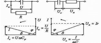
Operation of the equipment with the secondary circuit open is called idling, and with the load current connected - operating mode. In the first circuit of the circuit, the flow F0 creates a self-inductive emf, and when the secondary circuit is open, it balances part of the voltage. By transferring a load to the secondary winding, it is possible to cause the formation of a current I2, which excites its own flux F2. The total magnetic flux decreases, reducing the magnitude of the emf E1, and some part of U1 remains unbalanced.
At the same time, I1 increases and increases until the demagnetizing effect of the load current ceases. This helps restore F0 to approximately its original value.
The conductor of the secondary winding naturally has active resistance. If it increases, I2 and Ф2 decrease, causing an increase in Ф0 and an increase in emf E1. As a result, the balance between U1 and EMF E2 is disrupted - the difference between them decreases, reducing I2 to a value at which the total magnetic flux returns to its original value.
Calculation method
This process contributes to almost complete constancy of the magnetic flux values during operation of the transformer at idle and in operating mode. This property of the energy converter is called self-regulating ability, due to which the value of the load current I1 is automatically adjusted when the load current I2 fluctuates.
The process of converting electricity in transformer units is accompanied by losses and is reflected in the value of efficiency, which is the ratio of the supplied active power to the consumed one. The efficiency indicator reflects the ratio of active power at the input and output for a closed circuit. It is calculated using a simple formula:
Efficiency = (M1 / M2) * 100% or
ƞ = (P2 / P1) * 100%, where the active power in the windings of the input and output circuits is determined by measurement.
The measurement process can be simplified by connecting the active load current to the secondary winding. To determine the value of M2, use an ammeter connected to the secondary circuit. The dissipation flux will be insignificant, which allows us to approximately equate cos φ squared to unity.
This method of calculating efficiency is a direct measurement method. This theory of calculations leads to errors in calculations, since the efficiency of high-power transformers is very high and amounts to 0.98-0.99%. Despite the fact that the values of M1 and M2 differ insignificantly, in industrial equipment a slight difference in readings causes a significant distortion of the efficiency value.
To avoid errors, in practice, when measuring the efficiency of transformers, two methods are used: no-load test and short-circuit test.
The meaning of the first method is to supply the rated voltage to the primary circuit with the secondary circuit open. Energy is spent on losses in steel, the power of which can be measured with a wattmeter connected to the primary winding circuit.
Another method is to short-circuit the secondary circuit and simultaneously apply voltage to the primary circuit. Including a wattmeter in the first circuit allows you to measure the power, which reflects the loss of the copper conductor of the winding.
Voltage loss in transformer
Electrical machines > Transformers
Voltage loss in transformer
The voltage loss in the windings of a two-winding transformer is determined by the formulas: where P is the active load of the transformer, MW; Q is the reactive load of the transformer, Mvar; S is the total load of the transformer, MVA; U - voltage at the transformer terminals, kV; Un - rated network voltage, kV; cosj - load power factor of the transformer; R - active resistance of the transformer windings; X - reactance of the transformer windings: In formulas (5-26) and (5-27): Sн - rated power of the transformer, MVA;Un.t. - rated voltage of the transformer windings, kV; DРк.з - short-circuit losses in the transformer, MW; Ux - voltage drop, %, in the reactance of the transformer, determined by formula (9-7).
In formulas (5-24), (5-25), (5-26) and (5-27), all values must be assigned to either the high voltage side (HV) or the low voltage side (LV). In Table. Table 9-2 shows the values of the active and reactive resistances of the transformers in relation to the HV side. The recalculation of these resistances in relation to the LV side is carried out according to the formulas: where n is the transformation ratio of the transformer: where is the relative voltage value corresponding to a given branch of the HV winding; - rated transformation ratio of the transformer. The values of voltage losses in transformers at rated load and rated voltage at the terminals for various power factors are given in table. 5-29.
Table 5-29 Voltage loss, % in step-down transformers 6-35/0.4/0.23 kV at rated load
| Rated transformer power, kVA | Rated voltage of the HV winding, kV | At power factor | ||||||||||
| ,7 | 0,75 | 0,8 | 0,85 | 0,88 | 0,9 | 0,92 | 0,94 | 0,96 | 0,98 | 1,0 | ||
| 254063631001001601602502504004006306301 0001 0001 6001 600 | 6-106-106-10206-1020-356-1020-356-1020-356-1020-356-1020-356-1020-356-1020-35 | 4,394,344,294,684,275,804,165,654,075,554,025,514,675,404,685,414,625,36 | 4,314,244,184,544,155,574,025,403,925,293,865,244,455,124,465,134,395,07 | 4,204,114,044,364,015,293,855,103,734,983,674,924,184,794,194,804,124,74 | 4,043,943,844,133,814,943,624,723,504,593,424,523,854,393,864,403,784,33 | 3,923,803,703,963,664,673,464,443,324,313,244,233,614,093,624,103,544,03 | 3,823,693,583,823,544,473,324,233,184,093,104,013,423,873,443,883,353,80 | 3,703,563,443,663,404,243,173,993,033,842,943,763,213,613,223,623,143,54 | 3,553,413,283,473,233,962,993,702,843,552,753,462,963,312,973,322,893,24 | 3,373,213,083,233,023,622,773,352,613,192,523,102,662,942,672,962,582,87 | 3,112,942,802,902,743,162,462,882,302,712,202,612,252,452,262,462,172,38 | 2,402,202,032,031,971,971,661,661,481,481,381,371,201,211,221,221,121,12 |
Table for transformers GOST 12022-66 and 11920-66
Example 5-7
Determine the voltage loss in a 10/0.4 kV transformer with a power of 630 kva with a winding connection diagram U/Un-0, if the transformer load is S = 500 kva at cosj = 0.85, the transformer winding tap is -5% and the voltage value is on the secondary side transformer U=0.39 kV. Solution From the table. 9-2 for a transformer 630 kVA, 10/0.4 kV, we find the active and reactance of the transformer windings in relation to the HV side: The nominal transformation ratio of the transformer is equal to: The actual transformation ratio, taking into account the selected branch of the windings, is determined by the formula (5-30):
We recalculate the resistance of the transformer in relation to the LV side using formulas (5-28) and (5-29): Rated network voltage on the LV side of the transformer Un = 0.38 kV. For cosj = 0.85 sinj = 0.527. Voltage loss in the transformer determined by formula (5-25):
All pages of the section on websorPower transformers Transformer without a steel magnetic core (air transformer) Ideal transformer The simplest approximate equivalent circuits of a transformer with a steel magnetic core Calculations of electrical circuits with transformers Voltage loss in a transformer
Calculator
To simplify calculations, it is convenient to use an online calculator. The program algorithm allows you to calculate the energy losses of a transformer without complex formulas. But the results obtained should be considered as indicative. The following data is used to enter:
- the value Snom (kVA) is taken from the technical data sheet of the device;
- enter the value Ркз – reference (passport) parameter (kW);
- select Pхх in the technical documentation of the device (kW);
- indicate the load current Iхх in percentage terms (%);
- indicate the voltage Ucz - reference information (%);
- enter the load factor K in relative units;
- indicate the operating time of the device with maximum load Tm (hour);
- the annual number of operating hours of the unit Tg (hour) is taken from the actual operating mode of the equipment;
- average CO tariff for active electricity in the billing period (RUB/kW*hour).
After entering the data, the program calculates the required values.
Since energy losses lead to an increase in the consumption of materials and funds, they cause an increase in the cost of electricity. Minimizing the loss of unproductive energy consumption of power units makes it possible to design devices with maximum efficiency. By applying in practice methods for calculating active power losses of transformer units, it is possible to determine the cost-effectiveness of equipment operation and the need to install compensating equipment in closed circuits.
The concept of loss standard
This term means the establishment of economically sound criteria for non-target expenditure for a certain period. When standardizing, all components are taken into account. Each of them is carefully analyzed separately. As a result, calculations are made taking into account the actual (absolute) level of costs for the past period and an analysis of various opportunities that make it possible to realize the identified reserves to reduce losses. That is, the standards are not static, but are regularly revised.
The absolute level of costs in this case means the balance between the transferred electricity and technical (relative) losses. Technological loss standards are determined by appropriate calculations.