Transformer reactance: calculation formulas
We are accustomed to thinking that all magnetic fluxes in a transformer penetrate both windings and the magnetic circuit. If there were an ideal transformer, this would indeed happen. Unfortunately, in reality, part of the magnetic flux overcomes the insulating space, goes beyond the windings and closes in them (see Fig. 1). The result is transformer reactance. This phenomenon is also called magnetic flux dissipation.
Rice. 1. Diagram illustrating magnetic flux dissipation
There are other resistances in coils that cause power loss. These are: the internal resistance of the winding materials, and dissipations caused by inductive reactances. The set of magnetic flux dissipations is called the internal resistance or impedance of the transformer.
Reactive power losses
Let's remember how an ideal two-winding transformer works (see Fig. 2). When the primary winding is under alternating voltage (for example, from an electrical network), a magnetic flux will arise that penetrates the secondary inductor. Under the influence of magnetic fields, the secondary windings are excited, in the turns of which an EMF arises. When active power is connected to the device, alternating current begins to flow in the secondary circuit at the frequency of the input current.
Rice. 2. Transformer design
In an ideal transformer, a directly proportional connection is formed between the voltages in the windings. Their ratio is determined by the ratio of the number of turns of each coil. If U1 and U2 are the voltages in the first and second windings, respectively, and w1 and w2 are the number of turns of the windings, then the formula is valid: U1 / U2 = w1 / w2 .
In other words: the voltage in the working winding is as many times greater (less) as the number of windings of the second coil is increased (decreased) in relation to the number of turns forming the primary winding.
The quantity w1 / w2 = k is usually called the transformation coefficient. Note that the formula given above also applies to autotransformers.
In a real transformer, part of the energy is lost due to magnetic flux leakage (see Fig. 1). The zones where the concentration of scattering fluxes occurs are indicated by dotted lines. The figure shows that the leakage inductance covers the magnetic circuit and extends beyond the windings.
The presence of reactive resistance in combination with the active resistance of the windings leads to heating of the structure. That is, when calculating efficiency, it is necessary to take into account the impedance of the transformer.
Let us denote the active resistance of the windings by the symbols R1 and R2, respectively, and the reactive resistance by the letters X
1 and X2.
Then the impedance of the primary winding can be written as: Z1= R1+jX1 . For the working coil, we will accordingly have: Z2= R2+jX2 , where j is a coefficient depending on the type of core.
Reactance can be represented as the difference between inductive and capacitive indicators: X = RL – RC. Considering that RL = ωL , and RC = 1/ωC , where ω is the current frequency, we obtain a formula for calculating reactance: X = ωL – 1/ωC .
Without resorting to a chain of transformations, we present a ready-made formula for calculating the impedance, that is, for determining the impedance of the transformer:
The total resistance of the transformer must be known to determine its efficiency. The magnitude of losses mainly depends on the material of the windings and the design features of the transformer iron. Vortex flows in monolithic steel cores are much greater than in multi-section magnetic core structures. Therefore, in practice, cores are made from thin plates of transformer steel. In order to increase the resistivity of the material, silicon is added to the iron, and the plates themselves are coated with insulating varnish.
To determine the parameters of transformers, it is important to find active and reactance resistance and calculate no-load losses. The above formula is not practical for calculating impedance due to the complexity of measuring inductive and capacitive reactance values. Therefore, in practice, other calculation methods are used, based on the characteristics of the operating modes of power transformers.
Operating modes
A two-winding transformer is capable of operating in one of three modes:
- idle;
- in load mode;
- in a short circuit state.
To carry out calculations of the modes of electrical conductivity circuits, they are replaced by a load, the value of which is equal to the losses when operating in idle mode. Calculations of equivalent circuit parameters are carried out experimentally, transferring the transformer to one of the possible modes: no-load or short-circuit. In this way you can determine:
- level of active power losses during idle operation;
- the magnitude of active power losses in a short-circuited device;
- short circuit voltage;
- no-load current strength;
- active and reactance in a short-circuited transformer.
Idle settings
To switch to idling operation, it is necessary to remove the load on the secondary winding, that is, open the electrical circuit. There is no voltage in an open coil. The main component of the current in the primary circuit is the current arising in the reactances. Using measuring instruments, it is quite easy to find the basic parameters of the alternating magnetizing current, using which you can calculate the power loss by multiplying the current strength by the applied voltage.
The idle measurement diagram is shown in Figure 3. The diagram shows the points for connecting measuring instruments.
Rice. 3. Idle mode diagram
The formula used to calculate the parameters of reactive conductivity looks like this: W = Ix%*Snom / 100* Unom2 The multiplier of 100 in the denominator is used because the value of the no-load current Ix is usually expressed as a percentage.
Short circuit mode
To switch the transformer to operate in short-circuit mode, the low-voltage winding is short-circuited. The second coil is supplied with a voltage such that the rated current circulates in each winding. Since the applied voltage is significantly lower than the rated voltages, the active power losses in conduction are so small that they can be neglected.
Thus, we are left with active powers in the transformer, which are spent on heating the windings: ΔPk = 3* I1nom * Rt . Expressing the current I1 nom through the voltage Uka and resistance Rt, multiplying the expression by 100, we get a formula for calculating the voltage drop in the zones active resistance (in percent):
The active resistance of a two-winding power transformer is calculated using the formula:
Substituting the value of Rt into the previous formula, we get:
Conclusion: in a short-circuited transformer, the voltage drop in the active resistance zone (expressed in %) is directly proportional to the amount of active power loss.
The formula for calculating the voltage drop in the reactance zones is:
From here we find:
The values of reactive resistance in modern transformers are much less than active ones. Therefore, we can assume that the voltage drop in the reactance zone Uk p ≈ Uk, therefore for practical calculations you can use the formula: XT = Uk*Unom2 / 100*Snom
The reasoning given above is also valid for multi-winding, including three-phase transformers. However, calculations are carried out for each winding separately, and the problem comes down to solving systems of equations.
Knowledge of power factors, dissipation resistance and other parameters of magnetic circuits allows you to make calculations to determine the values of rated loads. This, in turn, ensures that the transformer operates within the rated power range.
www.asutpp.ru
Reactive power losses
Let's remember how an ideal two-winding transformer works (see Fig. 2). When the primary winding is under alternating voltage (for example, from an electrical network), a magnetic flux will arise that penetrates the secondary inductor. Under the influence of magnetic fields, the secondary windings are excited, in the turns of which an EMF arises. When active power is connected to the device, alternating current begins to flow in the secondary circuit at the frequency of the input current.
Rice. 2. Transformer design
In an ideal transformer, a directly proportional connection is formed between the voltages in the windings. Their ratio is determined by the ratio of the number of turns of each coil. If U1 and U2 are the voltages in the first and second windings, respectively, and w1 and w2 are the number of turns of the windings, then the formula is valid: U1 / U2 = w1 / w2 .
In other words: the voltage in the working winding is as many times greater (less) as the number of windings of the second coil is increased (decreased) in relation to the number of turns forming the primary winding.
The quantity w1 / w2 = k is usually called the transformation coefficient. Note that the formula given above also applies to autotransformers.
In a real transformer, part of the energy is lost due to magnetic flux leakage (see Fig. 1). The zones where the concentration of scattering fluxes occurs are indicated by dotted lines. The figure shows that the leakage inductance covers the magnetic circuit and extends beyond the windings.
The presence of reactive resistance in combination with the active resistance of the windings leads to heating of the structure. That is, when calculating efficiency, it is necessary to take into account the impedance of the transformer.
Let us denote the active resistance of the windings by the symbols R1 and R2, respectively, and the reactive resistance by the letters X1 and X2. Then the impedance of the primary winding can be written as: Z1= R1+jX1 . For the working coil, we will accordingly have: Z2= R2+jX2 , where j is a coefficient depending on the type of core.
Reactance can be represented as the difference between inductive and capacitive indicators: X = RL – RC. Considering that RL = ωL , and RC = 1/ωC , where ω is the current frequency, we obtain a formula for calculating reactance: X = ωL – 1/ωC .
Without resorting to a chain of transformations, we present a ready-made formula for calculating the impedance, that is, for determining the impedance of the transformer:
The total resistance of the transformer must be known to determine its efficiency. The magnitude of losses mainly depends on the material of the windings and the design features of the transformer iron. Vortex flows in monolithic steel cores are much greater than in multi-section magnetic core structures. Therefore, in practice, cores are made from thin plates of transformer steel. In order to increase the resistivity of the material, silicon is added to the iron, and the plates themselves are coated with insulating varnish.
To determine the parameters of transformers, it is important to find active and reactance resistance and calculate no-load losses. The above formula is not practical for calculating impedance due to the complexity of measuring inductive and capacitive reactance values. Therefore, in practice, other calculation methods are used, based on the characteristics of the operating modes of power transformers.
1.4. Determination of transformer resistance.
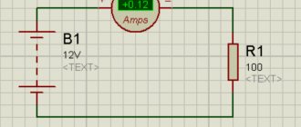
Transformer resistances are found based on short circuit experience. The experimental scheme is shown in the figure.
From the diagram of the short circuit experiment it is clear that the short circuit voltage is equal at the rated load of the transformer.
Multiplying by
numerator and denominator, we get
For power transformers
, therefore, for them it is accepted with sufficient accuracy that
In a short circuit experiment, the wattmeter shows the sum of active power losses in steel and copper. Since U
k in % is 5 – 17%, then the magnetic flux proportional to the voltage in the steel core is small.
Active power losses in steel are approximately proportional to the square of the magnetic flux, so in a short circuit experiment they are very small and can be neglected.
As a result:
, where
or
1.5. Determination of transformer conductivities.
The conductivities gt and bt are found from the data of the idle run experiment. The experimental scheme is shown in the figure.
The no-load current is small and amounts to . The power losses in the primary winding, depending on the square of this current, are insignificant, as a result of which it is assumed that .
Losses in steel are determined by the expression where
– active component of the no-load current, which is equal to
Expressed in terms of power losses in steel are equal
The no-load currents, the active component of which covers active power losses in the steel core due to hysteresis and eddy currents, are 5–10 times less than the reactive component. Approximately accepted
From here
finally we have
.
Thus
Three-winding transformers.
Step-down substations sometimes feed distribution networks of two voltages, for example 10(6) and 35 kV. If the loads of these networks are comparable, then it is advisable to use three-winding transformers with two secondary windings instead of installing two two-winding transformers.
2.1. Connection of windings of three-winding transformers.
In power transformers, the HV and MV windings are connected in a star, the LV winding in a triangle. Accordingly, the connection group is u/u/D-0-11.
At traction substations, three-winding transformers are installed to jointly power the traction and the area.
Their primary winding is connected in a star, and the traction winding in a triangle. The connection of the district winding depends on its voltages. If it has a voltage of 11 (6.6 kV), then it is connected in a triangle, with a voltage of 38.5 kV - in a star.
studfile.net
Operating modes
A two-winding transformer is capable of operating in one of three modes:
- idle;
- in load mode;
- in a short circuit state.
To carry out calculations of the modes of electrical conductivity circuits, they are replaced by a load, the value of which is equal to the losses when operating in idle mode. Calculations of equivalent circuit parameters are carried out experimentally, transferring the transformer to one of the possible modes: no-load or short-circuit. In this way you can determine:
- level of active power losses during idle operation;
- the magnitude of active power losses in a short-circuited device;
- short circuit voltage;
- no-load current strength;
- active and reactance in a short-circuited transformer.
Idle settings
To switch to idling operation, it is necessary to remove the load on the secondary winding, that is, open the electrical circuit. There is no voltage in an open coil. The main component of the current in the primary circuit is the current arising in the reactances. Using measuring instruments, it is quite easy to find the basic parameters of the alternating magnetizing current, using which you can calculate the power loss by multiplying the current strength by the applied voltage.
The idle measurement diagram is shown in Figure 3. The diagram shows the points for connecting measuring instruments.
Rice. 3. Idle mode diagram
The formula used to calculate the parameters of reactive conductivity looks like this: W = Ix%*Snom / 100* Unom2 The multiplier of 100 in the denominator is used because the value of the no-load current Ix is usually expressed as a percentage.
Short circuit mode
To switch the transformer to operate in short-circuit mode, the low-voltage winding is short-circuited. The second coil is supplied with a voltage such that the rated current circulates in each winding. Since the applied voltage is significantly lower than the rated voltages, the active power losses in conduction are so small that they can be neglected.
Thus, we are left with active powers in the transformer, which are spent on heating the windings: ΔPk = 3* I1nom * Rt . Expressing the current I1 nom through the voltage Uka and resistance Rt, multiplying the expression by 100, we get a formula for calculating the voltage drop in the zones active resistance (in percent):
The active resistance of a two-winding power transformer is calculated using the formula:
Substituting the value of Rt into the previous formula, we get:
Conclusion: in a short-circuited transformer, the voltage drop in the active resistance zone (expressed in %) is directly proportional to the amount of active power loss.
The formula for calculating the voltage drop in the reactance zones is:
From here we find:
The values of reactive resistance in modern transformers are much less than active ones. Therefore, we can assume that the voltage drop in the reactance zone Uk p ≈ Uk, therefore for practical calculations you can use the formula: XT = Uk*Unom2 / 100*Snom
The reasoning given above is also valid for multi-winding, including three-phase transformers. However, calculations are carried out for each winding separately, and the problem comes down to solving systems of equations.
Knowledge of power factors, dissipation resistance and other parameters of magnetic circuits allows you to make calculations to determine the values of rated loads. This, in turn, ensures that the transformer operates within the rated power range.
Calculation formulas for the main parameters of transformers
I present to your attention a table with calculation formulas for determining the main parameters of power transformers , as well as a table of the loss change coefficient kn.p. in transformers.
Table 1 – Calculation formulas for determining the main parameters of transformers
| Name of quantities | Formulas | Designation |
| Winding currents | I1, I2 - currents of the primary and secondary windings, A; U1, U2 - the same line voltage, V; | |
| Transformation ratio | w1, w2 – number of turns of one phase of windings | |
| Reducing the values of the secondary winding to the primary | The given values are indicated by a prime | |
| Short circuit resistance | rk, xk, zk – active, reactive and impedance of the short-circuit phase of the transformer | |
| Active power losses in a transformer under load | ∆Рх – active no-load losses, kW; ∆Рк – active load losses in windings at rated current, kW; kз – load factor; St.nom. – rated power of the transformer. | |
| Reduced active power losses in the transformer under load | S – actual load of the transformer; kip – coefficient of loss change, kW/kvar; ∆Qх – reactive idle power losses; ∆Qк – short-circuit reactive power losses; kip values are given below. | |
| Short circuit voltage | Uк – short-circuit voltage, V or %; Uк.а, Uк.х – active and reactive components of short-circuit voltage, V or %. | |
| Transformer short-circuit power and current | Sk – short-circuit power, kVA | |
| Number of turns of the primary winding | U1ph – phase voltage of the primary winding, V Ф – phase flux; Ф = Vst*Qst μs; Inst – induction in the rod; Vst = 13 – 14.5 103 G; Qst – active cross section of the rod, cm2 | |
| Active and reactance of a two-winding transformer, Ohm | ||
| Voltage drop in transformer windings under load | If the load is mixed (resistive and inductive), then the second term can be neglected | |
| Voltage loss when starting an asynchronous squirrel-cage motor (approximately) | ∆U – voltage loss, %; Sdv. – rated motor power, kVA; S2 – power of other consumers connected to the transformer buses, kVA; Ki is the multiple of the starting current relative to the rated current. | |
| Transformer efficiency |
raschet.info
Identification of windings by visual inspection.
When visually inspecting a transformer, pay attention to its outer protective insulation layer, because some models depict an electrical circuit on the outer layer indicating all windings and terminals; For some models, the winding terminals are only marked with numbers. You can also find old domestic transformers, on the outer layer of which they indicate markings in the form of a digital code, according to which reference books for radio amateurs contain all the information about a specific transformer.
If you come across a transformer without identification marks, then pay attention to the diameter of the winding wire with which the windings are wound. The diameter of the wire can be determined by the protruding terminals of the ends of the windings, released for fastening to the contact petals located on the elements of the transformer frame. As a rule, the primary winding is wound with a wire of a smaller cross-section in relation to the secondary. The diameter of the secondary winding wire is always larger.
An exception may be step-up transformers operating in voltage and current converter circuits. Their primary winding is made of thick wire, as it generates high voltage in the secondary winding. But such transformers are very rare.
In the manufacture of transformers, the primary winding is usually wound first. It can be easily identified by the protruding ends of the winding terminals located closer to the magnetic core. The secondary winding is wound on top of the primary, and therefore the ends of its terminals are located closer to the outer layer of insulation.
In some models of network transformers used in power supplies for household radio equipment, the windings are placed on a plastic frame, divided into two parts: one part contains the primary winding, and the other contains the secondary winding. A flexible mounting wire is soldered to the terminals of the primary winding, and the terminals of the secondary winding are left in the form of a winding wire.
Resistance of equivalent circuit elements in a 0.4 kV network
Content
In order to calculate short-circuit currents in a network up to 1000 V, you should first draw up an equivalent circuit that consists of all the resistances of the short-circuit circuit. Active and inductive resistances of all equivalent circuit elements are expressed in milliohms (mOhm).
How to determine the resistance of individual elements of an equivalent circuit , you will learn about this in this article.
The active and inductive resistances of the supply power system are calculated on the HV side of the step-down transformer and brought to the LV side according to formula 2-6 [L3. With. 28].
In practice, you can ignore the active resistance of the power system, and equate the value of inductive reactance to the total resistance of the power system (this will not affect the accuracy of the calculations). In this case, the value (in Ohms) of the inductive (impedance) resistance of the power system is determined by formula 2-7 [L3. With. 28].
After determining the inductive reactance of the system using formula 2-7 [L3. With. 28], this resistance must be brought to the LV side according to formula 2-6 [L3. With. 28].
The inductive reactance of the system can also be determined using the formulas presented in GOST 28249-93:
As we can see, formula 1 from GOST 28249-93 corresponds to formulas 2-6, 2-7 from [L3. With. 28].
Example
Determine the resistance of the power system, taking into account that the short-circuit current on the side of the power system at the HV terminals of a 6/0.4 kV transformer is 19 kA in maximum mode, and 13 kA in minimum mode.
Solution
We determine the inductive reactance of the power system using formulas 2-6, 2-7.
Resistance of the power system in maximum mode, reduced to a voltage of 0.4 kV:
Resistance of the power system in minimum mode, reduced to a voltage of 0.4 kV:
The values (in mOhm) of the total (zt), active (rt) and inductive (xt) resistance of the step-down transformer brought to the LV side are determined by the formulas: 2-8, 2-9, 2-10 [L3. With. 28].
On most 10(6)/0.4 kV transformers, it is possible to regulate the voltage by switching without excitation (SWB) when the transformer is disconnected from the network on both the high and low voltage side. The voltage is regulated on the higher voltage side by an amount of ±2x2.5% of the nominal value.
For transformers with a PCB regulation limit of ±2x2.5%, the impedance will vary within:
The values of the inductive and active resistance of the transformer according to GOST 28249-93 are determined by the formulas:
raschet.info
Topic 2.2 Resistance and conductivity of transformers
And autotransformers
The L-shaped equivalent circuit of the transformer consists of longitudinal resistance Z
t=
R
t+
jX
t and transverse conductivity
Y
t=
g
t–
jb
t.
2.2.1. Resistance and conductivity
two-winding transformers.
Active resistance R
t models the process of electricity losses due to heating of the transformer windings (copper losses);
inductive reactance X
t – losses caused by leakage fluxes;
active conductivity g
t – losses due to magnetization reversal and eddy currents (losses in steel);
reactive (inductive) conductivity b
t – losses due to magnetizing power. It should be noted that the inductive reactance of transformers is many times greater than the active reactance, especially for powerful transformers [5].
The parameters of the L-shaped equivalent circuit of the transformer are determined by the following formulas:
, (2.8)
, (2.9)
, (2.10)
. (2.11)
In these formulas S
nom – rated power of the transformer;
U
is the voltage to which the transformer parameters are reduced (usually the rated voltage of the high voltage winding);
Δ P
к – short circuit losses;
u
к – short circuit voltage, %;
Δ P
x - no-load losses;
I
x – no-load current, %. The last four parameters are the transformer catalog data.
2.2.2. Resistance and conductivity
three-winding transformers.
The equivalent circuit of a three-winding transformer is shown in Figure 2.1.
Figure 2.1 L-shaped equivalent circuit of one phase of a three-winding transformer
For three-winding transformers, factories give short-circuit losses for the worst case, i.e. for the case of maximum losses Δ Р
k. max.
The active resistance of each beam of a three-winding transformer is determined by the following formula
. (2.12)
For three-winding transformers, short-circuit voltages are given by the factories for each pair of windings as a percentage of the rated one. Therefore, the inductive reactance of each beam, %, must be determined separately using the expressions:
; ; . (2.13)
To determine the values of the short circuit voltage between the windings, one of the windings is short-circuited, a voltmeter is connected to the other, and the third remains open. Then the voltmeter shows the short circuit voltage between the first two windings u
I
nom flows through them Thus, we can write
u
k (B–N) =
u
k. B +
u
k. N;
u
k (B–C) =
u
k. B +
u
k. C; (2.14)
u
k (C–H) =
u
k. C +
u
k. N.
Having solved equations (2.14) together, we can find the short circuit voltage, %, for each beam:
u
k. B = 0.5(
u
k (V–C) +
u
k (V–H) –
u
k (C–H));
u
k. C = 0.5(
u
k (B–C) +
u
k (C–H) –
u
k (B–H)); (2.15)
u
k. N = 0.5(
u
k (B–H) +
u
k (C–H) –
u
k (B–C)).
Substituting these values into expression (2.13), we determine the inductive reactance of each beam of the transformer.
Conductivities do not depend on the number of windings in the transformer and are determined in the same way as for a two-winding transformer according to (2.10) and (2.11).
2.2.3. Resistance and conductivity of autotransformers.
Conversion of transformer parameters to rated power
An autotransformer (Figure 2.2) is usually called a transformer in which the medium (C) voltage winding is part of the high (V) voltage winding [5].
Figure 2.2. Autotransformer winding connection diagram
Thus, the high voltage winding consists of two parts: a series winding (s) between V
and
C
, through which only the highest voltage current
IB
, and the common winding (about) between
C
and 0, through which currents of higher and medium voltage flow in opposite directions, i.e. their difference:
I
about =
I
C –
I
V. (2.16)
The low voltage (H) winding has a magnetic connection with the other windings. The power of the LV winding is only 20–50%, if we take the power of each of windings B and C equal to 100%. The H winding is always connected in a triangle to compensate for third harmonic currents. Sometimes there is nothing connected to this winding.
Autotransformers have the following advantages: lower cost, dimensions, weight and power losses. The disadvantage is the electrical connection between the high and medium voltage side, for example, if the transformer is grounded for the high voltage side, it will also be grounded for the medium voltage side.
An autotransformer can be obtained from a transformer with separately operating windings, series and common, by connecting these windings electrically. In this case, all processes in the steel windings of the autotransformer and the transformer (Figure 2.1, a, b) are the same. Therefore, their dimensions, losses in windings and steel, etc. are the same. However, the power transmitted through an autotransformer is greater than through a transformer.
Active resistances R
t.
For autotransformers, active power losses are given by factories not as maximum Δ Р
km for the entire transformer, as was the case with three-winding transformers, but for each pair of windings, i.e. Δ
Р
(В–С), Δ
Р
(В–Н ), Δ
Р
(С–Н).
To determine the active resistance of the star rays R
t B and
R
t C in the equivalent circuit of a three-winding autotransformer, you can use expressions similar to (2.15) for engineering calculations with sufficient accuracy (neglecting the power of the magnetization circuit):
Δ P
k В = 0.5(Δ
Р
к (В–С) + Δ
Р
к (В–Н) – Δ
Р
к (С–Н));
Δ P
k C = 0.5(Δ
R
k (V–C) + Δ
R
k (C–H) – Δ
R
k (V–H)). (2.17)
Respectively
R
t V = Δ
P
k V
U
2/
S
2nom;
R
t C = Δ
P
to C
U
2/
S
2nom. (2.18)
Resistance R
t depends on the power of this winding in the same way as active resistances in three-winding transformers.
Inductive reactances X
t.
These resistances are determined in the same way as for three-winding transformers according to (2.13) and (2.15).
Conductivities do not depend on the nature of the connection of the windings or their number and are determined in the same way as for two-winding transformers according to (2.10) and (2.11).
SECTION 3. ANALYSIS OF NETWORK OPERATING MODES
Calculation of single-phase short-circuit currents in a 0.4 kV network
In this article we will talk about determining the current value of a single-phase short-circuit current. in 0.4 kV networks with a solidly grounded neutral.
This issue is very relevant, since 0.4 kV electrical networks are the most common.
Currently, there are two methods for calculating a single-phase short circuit - exact and approximate, and both methods are based on the method of symmetrical components.
Accurate method for determining single-phase fault current
1.1 The exact method for determining the single-phase short circuit current is presented in GOST 28249-93, formula 24, and is calculated using the formula:
Using this method, it is possible to determine with a high degree of accuracy short-circuit currents with known resistances of the positive, negative and zero sequence of the phase-zero circuit.
Unfortunately, in practice, this method is not always possible to use, due to the lack of reference data on positive, negative and zero sequence resistances for cables with aluminum and copper conductors, taking into account the methods of laying phase and neutral conductors.
Approximate method for determining single-phase short-circuit current
2.1 An approximate method for determining the single-phase short-circuit current at high power of the supply power system (Xc < 0.1Хт), is calculated using the formula [L1, p. 4 and L3, p. 39]:
Where:
- Uph – phase voltage of the network, V;
- Zt – total resistance of the transformer to the current of a single-phase short circuit to the body, Ohm;
- Zpt – total resistance of the phase-zero loop from the transformer to the short-circuit point, Ohm.
2.2 If the supply power system has limited power, then the single-phase short circuit current is determined by formula 2-26 [L3, p. 39]:
2.3 The value of Z∑ is determined according to table 2.9 or can be determined using formula 2-25 [L3, p. 39]:
where: x1t and r1t; x2t and r2t; x0t and r0t - inductive and active resistance of the transformer to direct, negative and zero sequence currents, mOhm. Accepted according to table 2.4 [L3, p. 29].
The value of Zt/3 for various transformers with a secondary voltage of 400/230 V can be taken from tables 2, 3, 4 [L1, p 6.7].
The contact resistances of buses, devices, and current transformers are not taken into account in this method, since the arithmetic sum of Zt/3 and Zpt creates a certain margin.
2.4 Transformer impedance Zt is determined by formula 2-24 [L3, p. 39]:
2.5 The impedance of the phase-zero loop is determined by formula 2-27 [L3, p. 40]:
Where:
- Zpt.ud. – the total resistivity of the phase-zero loop for each section from the transformer to the short-circuit location is determined according to tables 2.10 - 2.14 [L3, p. 41,42] or according to tables [L2], mOhm/m;
- l – length of the section, m.
Below are reference tables with the resistivity values of the phase-zero loop for various cables and busbars according to [L3, pp. 41,42].
Reference tables 7, 10 with active resistance values of copper and aluminum wires and cables [L1, p. 6, 14].
raschet.info