A rather unpleasant situation, familiar to many - for no apparent reason, the light in the apartment (house) or in some rooms suddenly goes out, household appliances turn off. And at the same time, it is clearly clear that everything is fine with the neighbors’ electricity supply. Everyone's first reaction is probably the same - the owners check to see if the machine has been knocked out or if the fuse plug has blown.
How to find a broken wire in the wall
If this is really the case, and when the machine is restarted (the plug is replaced), the functionality of the home electrical network is restored, then the task is simplified. Of course, it is necessary to figure out the reason for the protection triggering - perhaps the permissible load was exceeded. But, in any case, the wiring is fine. But if there is voltage at the output of the fuses, but there is no voltage in the premises, there is a break somewhere. And the difficult task of restoring the home network lies ahead.
One of the most difficult questions in this case will be how to find a broken wire in the wall. We will consider it in this publication.
Signs of a cable break
Damage to electrical networks can be suspected if the electrical current supply partially disappears. A broken wire may be indicated by a lack of voltage in outlets located in a certain area, or by lighting not working in a separate room.
Sometimes wiring problems can also be accompanied by smoke or sparking in the cable. The cause of sparking can be not only a break, but also melting of the insulation as a result of illiterate selection of wires and cables.
Wire defects include breaks and breaks in the cord cores, as well as damage to the cable insulating sheath
Damage occurs on various sections of the network: the power supply may be disrupted at the point where the cable connects to the socket or switch; in the area between these devices and the box or lighting fixture.
Wire design
Any household electrical appliance works when it receives electric current from a voltage source through wires, cables and power cords. If a gap forms inside the circuit, the operation stops.
The electrical wire consists of:
- a conductive line made of metal conductors made of copper or aluminum wire;
- insulation layer (varnish, polymer coatings, paper, cotton, silk or other dielectric materials from their combinations).
The metal of the conductor core can be made:
- multi-strand twisting of thin wires:
- or a continuous, monolithic structure.
In everyday life there are wires of both types:
- monolithic conductors are used to work in a stationary electrical wiring circuit;
- stranded wires are used for transmitting high-frequency signals or where metal is subject to mechanical bending forces (cords of power supplies, portable devices, headphones, and other similar devices).
During manufacturing, transportation, installation and operation, the metal part of the core is affected not only by electrical, but also by mechanical loads. Excessive effort causes it to collapse. A broken wire prevents the electrical circuit from working. It must be found and eliminated.
Causes of malfunctions
If the operating rules for electrical communications are observed, they can serve regularly for decades. But in practice, damage to electrical networks is quite common, which can be caused by various reasons.
These factors include:
- Long-term operation of the cable . Wiring can function flawlessly for many years, but after a certain time limit it begins to deteriorate. In this case, twists scatter in the network and leaks appear, which regularly knock out the RCD (its absence affects the increase in leaks). Sooner or later, such violations lead to interruptions, and then to a complete cessation of the power supply.
- Mechanical damage . Without knowing the layout of electrical networks, when drilling holes and driving nails into the wall, you can easily touch a wire, causing it to break and sometimes short circuit. Sometimes minor mechanical damage has a delayed effect: in this case, the integrity of the core may not be damaged immediately, but after several months or even a year.
- Defective wire or poorly executed electrical installation . Damaged cables tend to become constantly hot, which can have fatal consequences. After a sudden power surge, such wires may break.
- Incorrect use of adapters . Electrical wiring malfunctions can be caused by improper use of extension cords or tees. This can happen if several high-power household appliances are connected to the device, for example, a washing machine and dishwasher.
If the adapter is used incorrectly, the cables that come from it are subject to overheating and increased stress, which can lead to melting of the insulation.
In all cases, it is necessary to identify the location of the cable damage in order to immediately repair the damage.
Determining the distance to the location of cable damage underground
Determining the distance to the defect is carried out using one of two methods - reflectometric (using reflectometers) and bridge (using cable bridges). These methods have significant differences.
Cable bridges localize damage based on cable resistance and capacitance. During the measurement, they use auxiliary (known good) conductors or cable pairs, which allows them to measure the resistance (capacitance) of the good pair, compare these readings with similar values on the damaged pair and determine the distance to the defect. During measurements, they most often use a voltage of 180V - 500V, which makes it possible to determine even minor damage to the cable insulation.
Cable reflectometers send a pulse with an amplitude of approximately 20V to the pair (the pulse width is adjusted depending on the length of the line) and the type of damage and the distance to it are determined by the shape and delay of the pulses reflected from inhomogeneities (defects). This method will not allow you to detect minor insulation damage, but it will easily detect mixed-up pairs, parallel taps, Pupin coils, etc.
To increase efficiency, these methods are increasingly being combined in one device. In this version, for example, the IRK-PRO Alfa and KB Svyaz Sova devices are presented. The SideKick Plus and Riser Bond 6000DSL analyzers described above also have such functions.
It should be noted that the accuracy of determining the distance to a defect by the device and the accuracy of localizing damage in the cable are different things. After all, the measured distance still needs to be accurately measured, and this is a very difficult task, taking into account the cable reserves on the couplings, the unevenness of the cable depth, etc. In addition, a large error is introduced by inaccurately entered linear values of resistance and capacitance or the propagation coefficient (and they constantly change during operation).
Instructions for finding the break point
If a malfunction is detected, it is necessary to immediately take measures to determine the cause of the damage and search for the approximate location of the electrical network defect.
First of all, you need to check which rooms have problems with the supply of electrical current.
Melted switches or sockets indicate that damage to the wiring occurred in the adjacent sections of the electrical network
Then you should find out whether the cable break affected lighting fixtures or sockets by checking them with a tester. Depending on the answers to the last question, you should follow the instructions below.
In this case, the malfunction may be caused by a faulty phase or neutral cable.
Broken phase wire
First of all, you need to determine which machine the damaged socket is connected to. Having identified the power source to which the faulty cable is connected, it is necessary to turn off the electricity and disconnect all wires from the panel: “zero”, “phase”, “ground” (if any).
In order to find the power source of the outlet, you need to switch the machine, while simultaneously checking with the indicator the presence or absence of a phase
Then you need to arm yourself with a multimeter, with which you should sequentially check all connections adjacent to the damaged object, starting from the cable in the panel.
In this way, you can identify the affected area: usually between two sockets there are two, and in the presence of “ground”, three wires. If in this area it is possible to identify only one vein (for example, a zero), we can safely assume that the break is located here.
Distribution boxes are often inaccessible because they are hidden under a layer of finishing materials. If you have access to such devices, it is advisable to open them, since damage to the cores often occurs in them.
If no malfunctions are found, you should check the non-functioning wires with an indicator, starting with the twists, and also inspect the terminal block and disassembled twists.
A wiring option is possible that does not require installation of a junction box. In this case, the cables run unhindered from one outlet to another, with two wires entering each outlet box, making up 4 cores. In this case, to identify the defect, it is necessary to remove the devices located at the beginning and end of the faulty section, and then examine all the wires with a multimeter.
Damage to the neutral wire
The search for a broken neutral wire is practically no different from the work on detecting a broken “phase”, but it has certain features.
You can find out about a break in the neutral wire at the contacts of the socket by bringing an indicator screwdriver to this place: it will glow in the “phase”, but will show the absence of a “zero”. In this case, it is useless to use a multimeter to check the voltage, since this device will show an arbitrary value from 0 to 220 V.
It is important to observe strict safety precautions: due to the existing phase, there is still a danger of electric shock even if the socket is not working.
It is quite difficult to understand the intricacy of wires placed inside the wall. To identify a faulty cable, it is often necessary to check the integrity of each network element
If a three-core cable is used to distribute electricity, a “grounding” conductor can be used as a last resort to transmit “zero”. However, in this case, the “ground” function will be absent from the socket: this is generally undesirable and unacceptable if we are talking about high-power household appliances, for example, a washing machine.
Malfunctions of fixed electrical wiring
To find them you will need:
- take into account the features of the scheme;
- prepare signs and instruments;
- analyze the technology of work using an open or closed installation method.
Wiring diagrams
Installation of current-carrying cores can be performed using two technologies:
- Open laying on the walls;
- Hidden inside the cavities and grooves of building structures.
In both cases, it is necessary to understand the current grounding circuit, check the voltage, find the phase, working zero and protective PE conductor.
In three-phase wiring, a zero break is especially dangerous.
Due to the redistribution of potentials along various chains, the voltage drop shifts across them. This can lead to high linear values on consumers connected to the phases in a conventional circuit.
Voltage testers
You can troubleshoot:
- capacitive voltage indicator;
- bipolar indicator;
- tester or multimeter in voltmeter mode;
- control lamp.
Working with a warning lamp is dangerous and is prohibited by modern regulations.
This method was previously used en masse, and even now there are many of its adherents.
I publish information about the warning lamp in order to explain the degree of risks to which a person exposes himself. I don't recommend working with her.
How to determine the phase wire, working zero and protective PE conductor
Electrical circuits for household wiring are created according to three rules:
- The phase potential has the largest value relative to the ground circuit, and switching devices and protections are always installed in its wires, which de-energize operating devices. The phase conductor is separated from the ground by the resistance of the connected load;
- The working zero is connected to the ground circuit at the supply transformer substation and can be interrupted in the apartment switchboard by an input circuit breaker or switch, as well as by the operation of RCD and differential circuit breaker protections;
- The protective PE conductor is always connected to the ground at the transformer substation and can additionally be connected to the building ground loop in TN-CS and TT systems. During operation of the circuit, it must not be broken under any circumstances. It is prohibited to install any switching devices and protections that act to disconnect the circuit.
To determine the phase, zero and PE conductor it is enough:
- measure the potentials of network sections using voltage gauges or indicators;
- Using switching devices and protections, clarify the belonging of each wire to the current grounding circuit.
Both points must be checked comprehensively, otherwise there is a high probability of error. To make it easier to find and install wires, they are marked with colors that all installers are recommended to adhere to. For example, the main lines of the protective PE conductor must be marked with yellow-green stripes.
In practice, this rule may be violated for various reasons, for example:
- neglect of standards;
- employee mistakes;
- the presence of a large supply of wires of different colors that need to be used quickly.
The color marking of insulation is intended to make the electrician’s work easier, but it is impossible to judge the state of the circuit from it: it is necessary to check sections of the circuit with electrical measurements.
Open wiring defects
This circuit is distinguished by an accessible arrangement of current-carrying lines and switching points: it is the easiest to detect faults. All live parts are clearly visible.
It is enough to open the housing of a socket, switch, light bulb socket or distribution box and you can use their contacts to ring the condition of the wires and cables. The use of cable skirting boards and plastic channels practically does not complicate this process.
An open wiring diagram is most convenient for finding and eliminating damage that occurs in it.
Malfunctions of a closed power circuit
Finding a break in a wire becomes more difficult if it is hidden inside a wall, floor or ceiling. But it can be found in various ways:
- using homemade indicators;
- industrial devices.
Homemade designs for searching for hidden wiring
The following schemes are popular among radio amateurs:
- on a field-effect transistor;
- chip K561LA7;
- transistor BC 547;
- two microcircuits.
It is quite possible to find the routes of power conductors from the noise picked up by a radio or smartphone.
The effectiveness of these methods depends on the depth of embedding of current-carrying lines into the wall, the absence of shielding materials, and the sensitivity of the measuring mechanism.
Industrial devices
A variety of professional sign designs work much better than homemade devices.
They have a number of additional functions for detecting various materials with a secretive location.
The owner of the Mobotix Webcams video clearly shows how the Mastech MS6812 cable tracker searches for a broken wire in the wall.
A thermal imager has particular advantages in searching for hidden highways. It allows you to remotely measure and monitor the temperature of contacts and conductors in an electrical power circuit.
If you still have questions about this topic, ask them in the comments.
Troubleshooting lighting wiring
If damage occurs between the box and the switch or an artificial light source, you should use an indicator (single-pole voltage indicator) to use it to identify the presence or absence of a “phase”.
If there is no light in one of the rooms, you must first check the condition of the lamps and sockets. If their condition does not cause concern, most likely it is a cable break.
To do this, open the switch from the lighting device; in the off position, the presence of “phase” on the contacts is checked. If it is absent, the break point is between the box and the switch.
If there is a “phase”, its presence is also checked on the lamp (in this case the switch is turned on). If there is no “phase” on all conductors, the place of damage should be looked for between the lamp and the box.
There is an option when, when the lighting is not working and there is no “phase” on the switch, the indicator shows its presence on the lamp. This situation means that the neutral and phase wires have swapped places.
To solve the problem, you need to trace the passage of the “phase” wire along the entire distance of the laid cable, starting from the box to the lamp and then to the switch. It is necessary to find the point where the wires were changed, disconnect them and make new fasteners, positioning the wiring correctly.
If a hidden wiring scanner is used to search for an open circuit, all actions to detect damage will take a couple of minutes:
Image gallery
Photo from
Convenient mobile device
Selecting a program for searching wiring
Sound signal and display
Repair of hidden wiring
When searching for damage, you should turn off the power supply to the cable, which can come from any source. In some cases, it may be necessary to burn through the wiring insulation to reduce the resistance level.
Finding a wiring break in a concrete or brick wall
To determine the location of damage in a wall made of brick or a concrete slab, you will need a transistor receiver, which can be used to detect hidden electrical wiring. It must be taken into account that in brick and concrete buildings all cables are directed horizontally and vertically, and are turned exclusively at an angle of 90 degrees. Knowing this, you can't go wrong when planning your cable layout.
The indicator should be placed along the wall above the cable, along its entire length. In this case, along the entire path the device will emit a sound signal, which will disappear the moment it reaches the place where the conductor breaks.
So, we figured out how to find a break in the wiring. If you do not have the necessary equipment or are not sure that you will correctly determine the location of the cable break and be able to repair it yourself, the best way out of the situation would be to invite an electrical installation specialist. Professional electricians have experience in this type of work and have the necessary electrical equipment, which means they will be able to find the fault and fix it within a fairly short time.
The entire diagnostic process is clearly shown in the video:
But if you have a great desire to save money and learn this procedure yourself, then we move on to the next stage - repairing the faulty line.
Searching for electrical wiring for preventive purposes
Usually, electricians or residents start looking for cables running through the apartment when there are problems with the light.
Meanwhile, you should take care of this in other situations:
- Before the planned redevelopment of the apartment. For any manipulations that even affect non-load-bearing structures (for example, when dismantling a partition or moving a doorway), it is important to take into account the location of electrical communications.
- Before installing sconces, hanging pictures or other wall accessories. To carry out such work, it is important to know where the cable is located so as not to stumble upon it when drilling holes or driving nails.
- When purchasing a home. Immediately after purchasing an apartment, it is advisable to draw up a plan for the electrical networks located along the walls and ceiling. On the diagram it is also worth noting the locations of sockets, switches, and junction boxes. Such markings will help when performing major/cosmetic repairs of the apartment, as well as when arranging furniture.
To search for an electrical route, you can use homemade or professional devices, which were described above.
Damage to cable lines: methods and methods of detection
Most large electrical connections between energy consumers and sources are made using cable lines. Most often this is a system of cables, couplings and fasteners parallel to each other. Damage, even to the smallest extent, is fraught with at least economic losses.
Most common damage
Cable lines can be laid underground or above ground. In this case, the nature of their damage will be similar. Most often the following happens:
- one or more cores may be damaged. In this case, the circuit is made to the ground;
- several wires are damaged with a short circuit to each other;
- grounding cable break;
- gap without grounding;
- the occurrence of a so-called “floating breakdown”, when a short circuit occurs when the voltage increases, after normalization the situation stabilizes;
- the integrity of the insulating layer is damaged.
Any damage requires immediate repair. As power supply patterns are disrupted, the reliability of the entire power supply to end users is called into question. This also affects the technical and economic indicators of the entire network as a whole.
The photo shows that we are dealing with a low-Ohm breakdown; such a place of damage is the easiest to find.
The causes of damage may be:
- In different seasons, soil movement occurs. For example, in the spring, as a result of sudden thawing of individual sections, the lines may experience excessive tension, which leads to rupture;
- violation of supply conditions, in particular overcurrent;
- violations in line laying technology;
- work near lines that violate boundaries;
- lines may be exposed to transit currents.
Elimination of broken phase and neutral wires
Having found out the exact location of the cable break and determined its peculiarity (damage to the “phase”, “zero”), you can begin to repair it.
To eliminate a damaged phase wire, follow these steps:
- First of all, you need to disconnect the phase wire.
- Using a hammer or other tool, remove plaster or other finishing from the wall surface. It is necessary to clear the area along the route by approximately 10-15 cm, covering the area to the right and left of the expected center of damage.
- It is necessary to separate the damaged core from the network, being careful not to touch the insulation on other cables.
- It is better to connect copper wiring by soldering. To do this, you need to take an additional piece of a similar product from which the repair jumper is made.
- It is also advisable to first place a polyvinyl chloride or heat-shrink tube on the core of the damaged cable. The ends of the jumper are twisted with the ends of the broken wire, after which the connections are soldered.
- Insulating tape is applied tightly (in several layers) to the repaired area, after which the tube covered with the wire is carefully pushed onto it. This ensures the tightness of the fastener.
Aluminum wires are less amenable to soldering, which also requires special solder and flux. In this case, the most reliable connection method will be the WAGO terminal, and the place of its attachment must be wrapped with electrical tape and additionally covered with sealant.
The wires can also be connected using a junction box. To do this, the insulation is removed from the broken wire, after which its ends are separated in different directions. Using a hammer drill equipped with a special crown, a hole is punched in the wall, the dimensions of which coincide with the parameters of the branch box.
The device is inserted into the opening, after which it is secured with alabaster. The wires are placed in the box, while the damaged wires are connected by color and wrapped with insulating tape. Finally, the box with the restored wires is closed with a lid.
If the cables are placed in special tubes, the damaged wires should be carefully pulled out, and new wires should be inserted in their place using a pulling device.
If the neutral cable is damaged at the beginning of work, it must be disconnected from the bus by attaching the phase conductor. The rest of the process coincides with the regulations described above.
After any type of repair, the grooves are covered with plaster. It is possible to apply voltage to the repaired wiring only after the coating has completely dried.
Determining the presence of a defect in a cable and its identification
Most often, to determine the presence of damage and identify its type, the same measurements are used as during routine measurements. To carry out such measurements, cable bridges, megohm meters, and ground resistance meters are used.
However, in some cases, multiple defects occur (several different types of defects at the same time). In this case, it is difficult to determine which of them makes the greatest contribution, since they mask each other. To determine such faults, it is necessary not only to measure the primary parameters of the cable, but also secondary ones: crosstalk, induced noise, attenuation, etc. In such cases, the repair team should be equipped with several instruments: cable bridge, megger, noise and interference analyzer, attenuation meter. There are, of course, complex analyzers that combine many functions in one housing. Thus, cable analyzers Greenlee SideKick Plus, Riser Bond 6000DSL, etc. have recently been often used to work with subscriber telephone lines.
They allow you to measure all the primary and secondary parameters of the cable line, send a tone to identify the pair at the return end, localize the damage using reflectometric and bridge methods, and even analyze the quality of the ADSL/VDSL channel by simulating a subscriber modem.
Laying open electrical networks
Repair work associated with a break in a hidden wiring usually requires complex construction and repair work: dismantling the finish, gating the walls, followed by sealing and covering a section of the wall with decorative materials.
Eliminating a broken hidden wire often requires dismantling the finishing, so it is advisable to combine such work with a major renovation of the premises
Since immediate implementation of such manipulations is not always possible, in some cases it can be recommended to lay a new wire along the surface of the wall, covering it in a special box or tube.
You will become familiar with a detailed description of the rules and technology for laying an open electrical network by reading our recommended article.
How to find the location of cable damage underground?
The operation of underground power and telecommunication cables is associated with carrying out scheduled and repair measurements, as well as localizing damage in cable lines.
During routine measurements, primary parameters are often checked: insulation resistance, loop resistance, asymmetry. Often a bridge meter is sufficient for these jobs.
Repair and restoration work is a more labor-intensive process that requires well-trained specialists and a wide range of equipment. Localization of the defect requires the following actions:
Finding the exact location
Having identified the approximate location where the broken wire is located, they begin a thorough search. You can find the exact location of the breakdown in different ways.
Opening walls during renovation
Opening up old electrical wiring is the best way to check it.
The simplest and most effective way to check the condition of wiring and eliminate tears is to completely clean the walls of finishing materials. Only in this case can you familiarize yourself in detail with the condition of the grooves, which were made specifically for hidden wiring. They differ from other surfaces in color, and several layers of putty are additionally applied to them.
This method is advisable only during a major overhaul, accompanied by the complete dismantling of all decorative coatings.
Logical search methods
Switching wiring lines are usually located above the sockets.
If the owner of the living space does not have a diagram of the electrical network, it can be recreated using logical methods. You should familiarize yourself with the basic principles of laying electrical communications:
- Most often, wiring is carried out at intervals of 10-15 cm from the ceiling or floor (the first option is more common).
- Installation of electrical communications is carried out strictly along vertical and horizontal grooves. Errors are possible, but small.
- Communication lines that are located above switches and sockets are always laid straight up. In these areas, hammering nails and using drills and hammer drills is prohibited.
Based on the location of switches and sockets in an apartment or house, you can recreate the electrical communications circuit with high accuracy.
Correct the situation: how to repair wiring
You have already found wiring in the wall, part of which has failed. What to do? Call professional electricians or repair it yourself as follows:
- find and use a hammer drill to carefully open the concrete screed and locate the cables or metal tubes in which the cables are located;
- cut off power to the entire apartment;
- Usually the tubes are collapsible, you need to remove the element that hides the damaged cable;
- Some of the damaged wiring must be cut out. To do this, use wire cutters;
- Now you have two wires in your hands - they need to be connected. A terminal or heat pipe will help. The first option is more reliable, the second is cheaper;
- wrap the wiring connection with electrical tape;
- close the tube or cable duct;
- seal the wall with concrete mortar.
Some DIYers perform soldering to connect wires.
After repairing a broken wiring in the wall, check the network for functionality. if everything is in order, the wall can be sealed with concrete
If cutting out part of the system does not help, you will have to change the entire cable.
Search using professional equipment
55555
Damage detection methods using professional equipment are the most reliable and accurate.
Special devices are of the following types:
- Electrostatic - based on the action of the electromagnetic field of the wire. Such devices are accurate and affordable and therefore the most common.
- Electromagnetic devices operate in the same way, but under a wire load of 1 kW. To do this, you need to connect any electrical device to the outlet.
- Metal detectors differ from other devices in that they generate an electromagnetic field. They record any changes in the explorer.
In real work the following devices are used:
- " Search " is based on the electrostatic principle. It has 4 modes of different sensitivity, with the support of which it is possible to ring the network in the wall up to 7 cm.
- Device "Woodpecker" . Rings the wall up to 8 cm to detect the electrical network.
- The CEM tester can find dead cables, as well as find broken and damaged cables.
- E-121 devices determine the state of electrical networks and the location of a breakthrough using special signals.
What you need to know about the device to connect wires
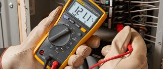
If you plan to test the wiring in your apartment, you need to know several fundamentally important facts about multimeters. First of all, it is worth noting that you can check the wire with the simplest device. An inexpensive Chinese model with minimal capabilities is quite suitable.
But at the same time, it is most convenient to use a device that has the dialing function itself. In order to set the device handle to the appropriate position, you need to turn it in the direction of the diode icon (as an option, an image of a sound wave can additionally be applied). This means that when checking the integrity of the wire, a sound signal will sound when the contacts are closed.
But the presence of sound is completely optional for testing wires with a multimeter. The fact that the circuit is broken will be indicated by a unit on the display, indicating that the resistance level between the probes is higher than the measurement limit. If there is no damage in the area under study, the resistance value will be displayed on the screen, which ideally should tend to zero (subject to operation in short-distance household networks).
Radio search
If you haven't thrown out your old radio yet, but keep it as a rarity, then you can use it to find wiring hidden in the wall. To do this you will need to set it to 100 kHz. It is also necessary that there is voltage in the network. Then pull the antenna to the maximum and lean it against the wall (you can do without an antenna). Slowly move the antenna along the wall (without touching, so as not to create friction) - the closer you are to the wiring, the more you will hear a characteristic crackling sound. Try to remain quiet so you can clearly hear the change in tone.
The radio allows you to find the wire with an accuracy of 10 cm - this is of course a large error, but if you just need to figure out where to hammer a nail for a picture, then this method is suitable. We do not recommend using this method to “open” the wall.