USB pinout on the motherboard: what, where and how
Most modern peripheral devices are connected via a universal serial bus. Therefore, the USB pinout on the motherboard plays a very important role in the operation of a modern computer. There are two ways to install these connectors. The first is mounting directly on the board. At the same time, it is displayed on the back side and is immediately ready for use. But it’s not always convenient to connect to it, so we developed another method. Its essence lies in a prepared footprint on the main PC board, to which wires from the front panel are connected. And the connector is located on it.
One USB 2.0 universal serial port has 4 pins. The first of them is designated “+5V”. It provides power to the peripheral device. The second and third are contacts through which information is transmitted. They are designated “DATA-” (minus data transfer) and “DATA+” (plus data transfer), respectively. The last one, the 4th one, which includes the USB pinout on the motherboard, is “GND” - ground supply. In accordance with today's standards, they are designated by the following colors: power - red, "DATA-" - white, "DATA+" - green, and "GND" - black.
Such interface connections are made in pairs, so the board has 2 USB standard connectors on one contact group. The wiring consists of 9 contacts: 4 to one connector, 4 to another, and the last two play the role of a so-called key. There is a pin installed in one place, but not in another. This is done so that it is impossible to confuse them and to make the connection correctly. The fitting from the front panel is made in a similar way. Therefore, when connecting, the first to the second should be installed without problems. If this does not happen, then you need to see if you are doing everything correctly.
Recently, version 3 of the USB standard has become increasingly popular. The pinout on the motherboard is significantly different, since significantly more wires are used to transmit information. There are only 9 of them in this design. In addition to the previously mentioned 4, 2 pairs of “Superspeed” + and 2 pairs of the same type, but only with a minus, are added, as well as “GND Drain” - additional ground. It is the larger number of wires that allows you to increase the data transfer speed. Their wires are designated blue by color, purple for minus, yellow, orange for plus, and another black for additional grounding. As the number of wires increases, the USB pinout on the motherboard increases in direct proportion. For this standard, 19 contacts are already used. One of them is a key, and its purpose is to ensure that the connection is correct.
Using the universal serial bus, a great variety of devices are connected to modern computers and laptops. A printer, scanner, MFP, flash drives, keyboard, mouse and other devices that significantly expand the capabilities of a PC - all of this is connected to the computer via this interface. It is not always convenient to connect to the back of the computer, and the number of integrated connectors may not be enough. It is to solve this problem that the USB pinout was made on the motherboard, which allows you to significantly increase the number of ports.
Pinout of USB type connectors.
- the first wire (red), it is supplied with a DC supply voltage of +5 V;
- the second contact (white), it is used to transmit information (D-);
- the third wire (green), it is also intended for transmitting information (D+);
- the fourth contact (black), zero supply voltage is supplied to it, it is also called the common wire.
- The first four pins are completely consistent with the 2.0 standard, so let's move on.
- The fifth pin (blue) is used to transmit information with a minus sign of USB3 (StdA_SSTX).
- The sixth pin is similar to the fifth pin, but with a plus sign (yellow).
- Seventh – additional grounding.
- The eighth pin (purple) is for receiving USB3 data (StdA_SSRX) with a minus sign.
- And finally, the last ninth (orange) is the same as the seventh pin, only with a plus sign.
Micro USB pinout:
- the first contact (red) is intended to supply + 5 V supply voltage;
- the second and third wires (white and green) are used for data transmission;
- the fourth lilac contact in type B connectors is not used, but in type A connectors it is connected to a common wire to support the OTG function
- the last, fifth, contact (black) is supply voltage zero.
Computer technology has swept the whole world and, probably, there is no person who does not know how to use a computer. But of course, people are interested not only in the computer itself, but also in all the additional elements that change, speed up and transform the operation of such computer equipment.
Thus, recently universal USB buses, which serve as a computer interface, have become very popular. They were invented in the twentieth century, but they began to be developed only three years later. And then a new USB model appeared, which, unlike the first one, worked much better. For example, the speed of its work was increased forty times. And therefore the charge lasted longer.
But after some time, the developers of such a computer interface as USB still had low speed
in order to use external hard drives and other devices whose speed was much greater. Therefore, the creators of USB had to change the device so that a new model was obtained. Now the speed of the third type of USB has become ten times faster. Of course, this also affected charging.
The USB cable consists of four conductors made of copper. These are two conductors intended for power supply, and the remaining conductors are in a twisted pair. This kit also includes a grounded braid.
USB cables have different physical ends. It depends on what device it is connected to. There are connections to the device itself and to the host. Moreover, USB can be with or without a cable. Another option is possible: the cable is built into the device itself. The cable is necessary to form an interface between the device and the host.
Let's now take a little look at the host. It acts as a special controller, which is programmed and controlled. Its task: to ensure the operation of the interface. By the way, the controller can most often be found in a microcircuit. A hub is required to connect the controller to other devices.
But in order to connect external devices to the hub, ports are used, at the end of which there are connectors. Cables help USB devices connect to ports. The device can be powered differently: from the bus or some kind of external power source.
It only takes a few minutes to get started and you can get started. First, the signal to start working is sent to the cable hub
, which further informs that the equipment is ready for operation.
But it is worth remembering one rule. Whenever you start pinouting a device, first determine what the pinout is on your cable. The USB connector helps you connect all external devices to your computer. This modern connection method replaces all those methods that were previously available. This connector provides additional options
: When operating computer equipment, any devices can be connected and immediately put into operation. It may also affect the charging operation.
Connecting additional USB ports on your computer
USB is one of the most popular interfaces, used in the vast majority of devices. Almost any equipment is connected through it - from a regular mouse to a smartphone or gamepad. The problem is that sometimes there are so many devices that there are not enough connectors to connect them.
If nothing can be done with the laptop (the only option is to purchase a special adapter), then there is always the opportunity to install a couple of additional ports in the computer system unit. Let's see how to connect USB to a computer.
Connecting the front ports
Almost all modern system units are equipped with several USB connectors, which are located not on the back, but on the front panel. However, they usually do not work because they are not connected to the mother card.
Attention! All work is carried out with the computer turned off from the network.
Turn off the computer and remove the side cover. Locate the wires that come from the front of the system unit. They can be a coiled bundle of several thin cables or a solid wire.
Look carefully at the motherboard - there should be a connector on it, next to which it says USB (usually it is blue). Install the wire from the front ports into the motherboard connector. Assemble the system unit and turn on the computer. Now the front ports should work: you can, for example, connect Lenovo to a computer using them.
Installation of additional equipment
Do you want to connect a gamepad to your computer, but all the connectors, including the front ones, are occupied by other devices? Then you will have to purchase a USB controller that is installed in the PCI slot on the motherboard. If you connected a video card, you can easily install another card if there is a free slot.
If there are no free slots left on the motherboard, use external USB hubs.
Such devices are connected to an existing connector and allow you to seriously increase the number of ports. By installing several controllers and adding a number of hubs, you can increase the number of working USB ports to 127 (this is a protocol limitation; it simply won’t work anymore). Of course, the average user is unlikely to need such a number, but a couple of ports will never be superfluous.
Port location and markings
Modern motherboards are most often equipped with four, six or eight such ports. Typically, two or four of them are tightly soldered in such a way that they can be accessed from the rear panel - where the keyboard and mouse jacks, audio outputs and everything else are located.
p, blockquote 4,0,1,0,0 –>
Other ports are located on the “mother” itself and are connectors with protruding pins. To connect the front ports to the motherboard, special connectors are used. With their help (and also to the USB port on the motherboard), a card reader is connected, if there is one of course.
This connector is missing one socket in the lower left corner. That is, where there should be 10 holes, there are only 9 of them. Thanks to this, it is easy to understand exactly how to connect this connector to the plug on the motherboard.
p, blockquote 5,0,0,0,0 –>
To connect an external port, you need to carefully push the plug onto the connector until it stops. Try not to make sudden movements left or right, as you may break one or more pins, which will cause that port to become inoperable and you will have to use the next one.
p, blockquote 6,0,0,0,0 –>
On the motherboard, these ports are most often located near the SATA interfaces and are marked with the abbreviation USB with a serial number. There is absolutely no difference in what exactly and where to connect - the ports work in parallel.
p, blockquote 7,0,0,0,0 –>
USB 2.0 connector pinout (types A and B)
Since the physical plugs and sockets of early versions 1.1 and 2.0 do not differ from each other, we will present the wiring of the latter.
Figure 6. Wiring the plug and socket of type A connector
Designation:
- A – nest.
- B – plug.
- 1 – power supply +5.0 V.
- 2 and 3 signal wires.
- 4 – mass.
In the figure, the coloring of the contacts is shown according to the colors of the wire, and corresponds to the accepted specification.
Now let's look at the wiring of the classic socket B.
Wiring of plug and socket type B
Designation:
- A – plug connected to the socket on peripheral devices.
- B – socket on a peripheral device.
- 1 – power contact (+5 V).
- 2 and 3 – signal contacts.
- 4 – ground wire contact.
The colors of the contacts correspond to the accepted colors of the wires in the cord.
USB ports not working due to controller damage
If none of the above actions helped restore the functionality of the USB ports, then you should check the USB controller of the motherboard, which may have failed. In this case, high-quality repairs and diagnostics should be entrusted to the specialists of the service center. As a way out of the problem, try installing an expansion card, the so-called USB PC controller, which is installed in the PCI slot on the motherboard. This solution is noticeably cheaper than repairing the motherboard USB controller, and when using an additional USB hub, the problem with the lack of ports will not be relevant at all.
USB device and purpose
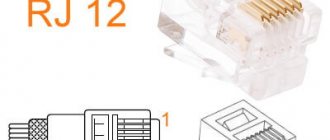
Rj-45: pinout, diagrams, standards and description of the standard
The first ports of this type appeared in the nineties of the last century. After some time, these connectors were updated to the USB 2.0 model. The speed of their work has increased more than 40 times. Currently, computers have a new USB 3.0 interface with speeds 10 times faster than the previous version. There are other types of connectors of this type, known as micro and mini USB, used in modern phones, smartphones, and tablets. Each bus has its own wiring or pinout. It may be required if you need to make your own adapter from one type of connector to another. Knowing all the intricacies of the arrangement of wires, you can even make a charger for a mobile phone. However, please remember that if connected incorrectly, the device may be damaged.
The USB 2.0 connector is designed as a flat connector with four pins. Depending on the purpose, it is labeled as AF (BF) and AM (BM), which corresponds to the common name “mother” and “father”. Mini and micro devices have the same markings. They differ from conventional buses in that they have five contacts. A USB 3.0 device looks similar to the 2.0 model, except for the internal design, which already has nine pins.
Features of cable wiring on connector contacts
There are no special technological nuances associated with soldering cable conductors on the contact pads of connectors. The main thing in this process is to ensure that the color of the pre-insulated cable conductors matches the specific contact (pin).
Color coding of conductors inside the cable assembly used for USB interfaces. Shown from top to bottom, respectively, is the color scheme of cable conductors for specifications 2.0, 3.0 and 3.1
Also, if you are wiring modifications of outdated versions, you should take into account the configuration of the connectors, the so-called “male” and “female”.
The conductor soldered on the male contact must match the soldering on the female contact. Take, for example, the option of wiring the cable to USB 2.0 pins.
The four working conductors used in this embodiment are usually marked in four different colors:
- red;
- white;
- green;
- black.
Accordingly, each conductor is soldered onto a pad marked with a connector specification of a similar color. This approach greatly simplifies the work of the electronics engineer and eliminates possible errors during the desoldering process.
A similar soldering technology is applied to connectors of other series. The only difference in such cases is the larger number of conductors that have to be soldered. To simplify your work, it is convenient to use special tools - a reliable soldering iron for soldering wires at home and a stripper for removing insulation from the ends of the wires.
Regardless of the connector configuration, screen conductor soldering is always used. This conductor is soldered to the corresponding contact on the connector, Shield - protective screen .
There are frequent cases of ignoring the protective screen, when “experts” do not see the point in this conductor. However, the lack of a screen dramatically reduces the performance of the USB cable.
Therefore, it is not surprising when, with a significant length of cable without a screen, the user experiences problems in the form of interference.
Wiring the connector with two conductors to organize a power line for the donor device. In practice, different wiring options are used, based on technical needs.
There are different options for soldering a USB cable, depending on the configuration of the port lines on a particular device.
For example, to connect one device to another in order to obtain only a supply voltage (5V), it is enough to solder only two lines on the corresponding pins (contacts).
Connect the USB connectors on the front panel of the case to the motherboard
Hello friends! The USB interface has become firmly entrenched in the life of any computer user. Thanks to its versatility and ease of use, you can use it to connect a lot of devices - a table lamp, a fan, a gamepad, a gaming wheel, a flash drive, an external hard drive and much more.
Frequent use of ports located on the rear side is not always convenient, as access to them can be difficult. Currently, most cases are equipped with USB ports on the front panel, the number of which may vary depending on the model.
How to connect USB to computer?
The most used port on a computer for connecting various devices is USB. You can use it to connect a regular flash drive, a phone, a camera, a video camera and other various gadgets. If your computer has only a few such ports, but you need many more, their number can be increased. Next, we will look at the question of how to connect USB to a computer and get the required number of these ports to connect various devices.
USB connection to motherboard
Almost every modern system unit has several USB connectors on the front panel, usually there are two of them. They are connected to the motherboard with a special cable, which should come with the system unit. Once upon a time, this cable looked like a bundle of cables with labeled tips at the end, and users had to look very carefully and check the documentation for the motherboard to ensure that each individual cable was connected correctly. Nowadays, this is most often a connector with a special safety lock that simply prevents incorrect USB connection.
Connecting USB to the motherboard from the front panel of the case
Thus, due to the front panel of the system unit, the number of USB connectors in the computer will be greater than that available on the rear output of the motherboard.
How can I additionally connect USB to my computer?
Additionally, you can connect USB to your computer using USB controllers installed as an additional device on the motherboard, or using USB hubs.
In the first case, an additional card is installed on the motherboard in the PCI slot, on the rear panel of which there are several USB ports.
USB controller
In the second case, a special cable is connected to the existing USB connector, at the end of which there are several USB connectors. Typically, such a hub contains two or four connectors.
USB hub with 7 connectors
Thus, by installing additional USB controllers and multiplying the number of USB ports using USB hubs, you can get a sufficient number of USB connectors, the number of which is limited by the USB protocol to 127.
Also interesting articles on the website chajnikam.ru: How to set a password to turn on your computer? How to speed up your computer as much as possible? Where to turn on wifi on a laptop? How to properly set up WiFi on a laptop?
USB 3.0 pinout types A and B
Bus version 3.0 has a 10 or 9 wire connection. 9 pins are used if Shield wire is missing. The contacts are arranged in such a way that devices of earlier modifications can be connected.
USB 3.0 wiring:
- A – plug;
- B – socket;
- 1, 2, 3, 4 – contacts that match the pinout of the contacts in specification 2.0, have the same color scheme;
- 5, 6 contacts for data transmission via the SUPER_SPEED protocol are designated SS_TX- and SS_TX+, respectively;
- 7 – grounding GND;
- 8, 9 – contact pads of wires for receiving data via the SUPER_SPEED protocol, contact designation: SS_RX- and SS_RX+.
USB 3.0 pinout (types A and B)
In the third generation, peripheral devices are connected via 10 (9 if there is no shielding braid) wires; accordingly, the number of contacts is also increased. But they are located in such a way that it is possible to connect devices of earlier generations. That is, the +5.0 V contacts, GND, D+ and D-, are located in the same way as in the previous version. The wiring for Type A socket is shown in the figure below.
Figure 8. Pinout of Type A connector in USB 3.0
Designation:
- A – plug.
- B – nest.
- 1, 2, 3, 4 – connectors fully correspond to the pinout of the plug for version 2.0 (see B in Fig. 6), the colors of the wires also match.
- 5 (SS_TX-) and 6 (SS_TX+) connectors for data transmission wires via the SUPER_SPEED protocol.
- 7 – ground (GND) for signal wires.
- 8 (SS_RX-) and 9 (SS_RX+) connectors for data receiving wires using the SUPER_SPEED protocol.
The colors in the figure correspond to those generally accepted for this standard.
As mentioned above, a plug from an earlier model can be inserted into the socket of this port; accordingly, the throughput will decrease. As for the plug of the third generation of the universal bus, it is impossible to insert it into the sockets of the early release.
Now let's look at the pinout for the type B socket. Unlike the previous type, such a socket is incompatible with any plug of earlier versions.
Wiring USB 3.0 type B
Designations:
A and B are plug and socket, respectively.
Digital signatures for contacts correspond to the description in Figure 8.
The color is as close as possible to the color markings of the wires in the cord.
Pinout of USB 2.0 connector types A and B
Classic connectors contain 4 types of contacts, while mini and micro formats contain 5 contacts. Wire colors in USB 2.0 cable:
- +5V (red VBUS), voltage 5 V, maximum current 0.5 A, intended for power supply;
- D- (white) Data-;
- D+ (green) Data+;
- GND (black), voltage 0V, used for grounding.
For mini format: mini-USB and micro-USB:
- Red VBUS (+), voltage 5 V, current 0.5 A.
- White (-), D-.
- Green (+), D+.
- ID - for type A it is closed to GND to support the OTG function, but for type B it is not used.
- Black GND, voltage 0V, used for grounding.
Most cables have a Shield wire; it has no insulation and is used as a shield. It is not marked and is not assigned a number. The universal bus has 2 types of connectors. They are designated M (male) and F (female). Connector M (male) is called a plug, it is inserted, connector F (female) is called a socket, it is inserted into it.
USB 3.0 and other subtleties
However, this is true in cases where ports of the same generation are used.
If the motherboard has a second or third revision, and a similar situation is observed with the front panel, compliance is necessary: USB 3.0 should be connected only to the corresponding slot on the motherboard, otherwise it will operate at USB 2.0 speed.
There is no need to worry about the pinout: it is the same for both revisions. In addition, motherboard manufacturers - ASUS, MSI, Gigabyte, Asrock and smaller companies, follow the same pinout that case manufacturers follow.
However, keep in mind that in rare cases it may still differ from the generally accepted one. You can find out the necessary information in the documentation for the motherboard.
Do not worry that you can connect the USB port incorrectly - in this case it simply will not work. Fortunately, it is impossible to break your computer this way.
How to connect USB to computer
For quite some time now, the USB format has become the standard format for organizing the connection of various devices. You can connect almost any gadget via USB: a flash drive, a computer mouse, a keyboard, a printer, a camera, a telephone, an mp3 player, and even a video recorder. It’s impossible to count everything. It would seem that it could be easier to connect.
USB connection to motherboard
Connecting USB to the motherboard is not a difficult task. The motherboard, as you can learn from our article, is the main part of a computer or laptop. And even a child can plug any compatible device into it. Please note that the picture shows two interfaces, USB 2.0 and the newer USB 3.0:
But what if you are just assembling your computer and need to make a USB connection on the front panel? That is, bring the USB connectors to the computer case. For this, any normal computer case has the corresponding wires:
Usually, they either come with the case or are already connected to it. To the motherboard, such a cable is connected to a special connector responsible for the USB interface. If you look closely, next to such a connector it should be written that it is responsible for this interface.
Now you know how to connect USB to the motherboard. Read smartronix.ru! PS You can read about connecting a hard drive via USB using the link provided. There is also nothing complicated there.
How to properly connect the front panel to the motherboard
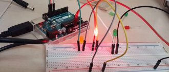
Often, a person who is assembling a computer for the first time (and it happens that it is not the first time) is faced with the fact that he does not know how to correctly and where to connect reset buttons, power buttons, LED indicators, a speaker that makes a squeak when turned on . I will show several examples by which you can understand the principle of how any front panel is connected correctly, and I will tell you some secrets that I use in my work.
There is nothing complicated about this if you adhere to simple rules and recommendations, which will be discussed now.
Where to connect the connectors?
This section is for those who do not know where exactly the front panel is connected. If this doesn't apply to you, skip straight to the next section and read on.
First, let's figure out what the place on the motherboard where the front panel of the computer is connected generally looks like. For clarity, I just want to show a few photos, from them you can easily determine what this connector looks like on the motherboard:
As you can see, they may differ slightly from each other
I also want to draw your attention to the fact that the location at the bottom right is not mandatory; sometimes these contacts are located in the center at the bottom of the motherboard
How to properly connect the front panel connectors?
Most motherboards already have markings on what to connect and where. Here is the simplest and most obvious example:
From left to right in the photo:
+MSG- (yellow) – connection of the computer operation indicator;
+HD- (blue color) – connection of the hard disk drive (HDD) operation indicator;
+PW- (red color) – connection of the power button;
-RES+ (green color) – connection of the reset button;
+SPEAK- (orange color) – connecting a speaker (the one that makes a squeak when turned on);
The colors don’t mean anything here, the manufacturer just decided to make such markings.
Rules for connecting connectors:
There are simple general rules, using which you will correctly and easily connect the front panel connectors to the motherboard:
Connecting the Power and Reset buttons has no polarity, since these buttons simply work to close the contacts
Despite the fact that the board indicates + and – for these buttons, they have no meaning. It is important to observe the polarity when connecting the LEDs and the speaker, otherwise they will not work. On the motherboard, for each type of connector, its plus is always on the left, and its minus is on the right. This is true for all motherboards
Connecting LEDs and Power Buttons
The computer case has power control buttons that connect to the motherboard, and LEDs to indicate the motherboard's activity. You must connect these buttons and indicators to the motherboard using wires from the front of the case shown in Figure #1, to the connector on the motherboard (Figure #2). The inscription on the motherboard near the panel connector shows the connection location of each wire and the polarity of each of them; however, inscriptions with designations are not always present on the motherboard.
Locate the front panel connectors in the computer case (see Figure 1). Next, we find the connector on the motherboard, usually it is located at the bottom of the motherboard, and is labeled PANEL1 or JFP1, it can be in different designs (see Fig. 2.0, 2.1).
Rice. No. 1. Front panel connectors.
Figure No. 2.0. Front panel connector on the motherboard.
Figure No. 2.1. Front panel connector on the motherboard.
The group of system cables shown in picture No. 1 have two wires that are color coded. The black or white wire is ground (GND), and wires of other colors (red, blue, green, orange) are power. The connection is made from left to right, when connected, all positive contacts will always be on the left except for the reset button, however, the polarity of the buttons is unimportant since the buttons close the contacts when pressed.
Simply install these wires to the connector with the same name on the motherboard, observing the polarity of the LEDs.
Figure No. 2.2. Front panel wire polarity.
Possible short names for them are listed below, which will be written on the connectors themselves.
PWR-SW, PW SW, PW = Power Switch (no polarity required). The control is the power button, which allows you to turn the computer on and off.
PWR-LED, P-LED, MSG = Power LED (polarity required). The indicator shows when the computer is turned on or in standby mode.
OTG - DIY adapter
Connector pinout of ethernet connector cable connection diagram
Not all old tablets support the function of connecting a flash drive or modem, but I will tell you how to outsmart them and connect a flash drive, modem, or even a hard drive to them. Good afternoon, homemade people!
Today I would like to present to your attention an OTG adapter.
First, I want to tell you what OTG is? This is a way to connect to your tablet or phone that supports the OTG function, printer, flash drive and even hard drive. This connection is also called USB-host.
You can also connect a keyboard or mouse to your gadget, if the gadget supports such a function.
And so, to create this miracle cable, we will need: • An old USB extension cord • Micro USB connector (you can get it from a regular USB cable for your device) • A soldering iron and soldering accessories
And so, let's go, to make such a cable, we will need to connect the 4th pin to the 5th pin of the micro USB connector
We must get to the fourth pin and connect it with a jumper to the GND wire as shown in the picture
After we connect the 4th and 5th contacts with a jumper, our gadget will perform the function of an active device and will understand that another passive device is about to be connected to it. Until we install a jumper, the gadget will continue to act as a passive device and will not see your flash drives.
But that’s not all; to connect a hard drive to a phone or tablet, this adapter will not be enough for us. To connect devices whose consumption is more than 100mA, namely 100mA can be supplied by the port of your device, we will need to connect additional power to our OTG cable, which should be enough for your hard drive to work.
Here is a diagram of such an adapter
Now it's time to start assembling. We take the old USB extension cable and cut it not too far from the 2.0 connector, since the current is only 100mA, to avoid large losses. Cut approximately in the same place as shown in the photo
Afterwards we clean our wire
Next, it needs to be tinned and soldered as shown in the diagram. You need to tin approximately 1mm of the wire, since the contacts on the micro USB connector are very small. This is what happened to me.
I connected pins 4 and 5 with a drop of solder.
Well, here is our entire cable assembled
All that remains is to check the functionality, take the tablet, insert the “adapter” and insert the flash drive into it, everything works, as the flashing LED on the flash drive and the tablet detecting the flash drive tell us.
Limitations: Old mobile phones cannot do this. The flash drive must be formatted in FAT32. The maximum capacity of the connected flash drive is limited by the hardware capabilities of the phone or tablet.
Types of USB connectors - main differences and features
There are three specifications (versions) of this type of connection that are partially compatible with each other:
- The very first version that has become widespread is v 1. It is an improved modification of the previous version (1.0), which practically did not leave the prototype phase due to serious errors in the data transfer protocol. This specification has the following characteristics:
- Dual-mode data transfer at high and low speed (12.0 and 1.50 Mbps, respectively).
- Possibility of connecting more than a hundred different devices (including hubs).
- The maximum cord length is 3.0 and 5.0 m for high and low transfer speeds, respectively.
- The rated bus voltage is 5.0 V, the permissible load current of the connected equipment is 0.5 A.
Today this standard is practically not used due to its low throughput.
- The dominant second specification today... This standard is fully compatible with the previous modification. A distinctive feature is the presence of a high-speed data exchange protocol (up to 480.0 Mbit per second).
A clear demonstration of the advantages of USB 2.0 over other interfaces (transfer speed 60 MB per second, which corresponds to 480 Mbit per second). Thanks to full hardware compatibility with the younger version, peripheral devices of this standard can be connected to the previous modification.
True, the throughput will decrease up to 35-40 times, and in some cases more. Since these versions are fully compatible, their cables and connectors are identical.
Please note that, despite the bandwidth specified in the specification, the actual data exchange speed in the second generation is somewhat lower (about 30-35 MB per second). This is due to the implementation of the protocol, which leads to delays between data packets. Since modern drives have a read speed four times higher than the throughput of the second modification, that is, it does not meet current requirements
Since modern drives have a read speed four times higher than the throughput of the second modification, that is, it does not meet current requirements.
- The 3rd generation universal bus was developed specifically to solve problems of insufficient bandwidth. According to the specification, this modification is capable of exchanging information at a speed of 5.0 Gbit per second, which is almost three times the reading speed of modern drives. Plugs and sockets of the latest modification are usually marked blue to facilitate identification of belonging to this specification.
USB 3.0 connectors have a characteristic blue color.
Another feature of the third generation is an increase in the rated current to 0.9 A, which allows you to power a number of devices and eliminate the need for separate power supplies for them.
As for compatibility with the previous version, it is partially implemented; this will be discussed in detail below.
General information about USB connectors
USB pinout.
Types of connectors and USB pinout by color USB (Universal Serial Bus) is a data transfer standard that was developed in 1994 to organize an interface between a computer and peripheral devices.
Now it is used both to transfer data between digital devices and to charge the batteries of a passive device from an active, so-called “host”. An example would be charging a phone from a computer.
Connectors are divided into three types:
The first type is usb 1.1
It was developed as one of the first to expand the functionality of a computer and made it possible to connect additional devices to the computer, including mobile phones for transmitting speech in digital form.
Due to the fact that the data transfer speed was low, it was replaced by usb 2.0. Currently, usb 1.1 is considered obsolete and is practically not used.
The second type is usb 2.0
The most common at the moment and widely used. Most electronic devices sold in electronics stores have USB 2.0 connectors, despite the fact that they no longer fully meet modern transfer speed requirements. In particular, hard drives can read information at a speed 3-4 times higher than the speed provided by this type of device. However, they remain common due to the fact that this speed is quite suitable for the operation of mice, keyboards and other devices.
The third type is usb 3.0
It is a new generation of devices, the transfer speed of which satisfies the fastest hard drives and provides a speed reserve for the future. Connectors of this type are specially marked in blue.
All connectors of the considered types have design differences that can be identified by the designation:
- A – connector is intended for connecting to a computer or device containing a USB controller (host);
- B - connector at the end of the cable connected to the peripheral device.
The letters F and M in the marking of usb connectors mean:
- F (female) – female-type connector;
- M (male) – connector type “plug” (male).
Mini-usb, and later micro-usb, were developed to connect to portable and mobile devices.
Connectors of the mini-AB and micro-AB types serve as adapters for connecting mini A and mini B, micro-A and micro-B to each other.
Connector pinout
The USB 2.0 connector pinout is as follows:
- The red wire is soldered to pin 1 of the connector: +5V power is supplied;
- White wire – to pin 2: information (D -);
- Green wire – to pin 3: information (D +);
- Black wire - to pin 4: common.
Mini and micro USB cables have five wires of different colors and a five-pin connector. The difference between the wiring of such micro connectors and the wiring of a USB 2.0 connector is as follows:
- wiring of the first three contacts is similar to usb 2.0;
- the lilac wire goes to pin 4 - this is ID; in connectors A – not used, in connectors B – connected to the housing;
- The black wire goes to pin 5 – common.
The USB 3.0 connector is wired as follows:
- The wiring of the first 4 contacts is identical to the wiring of the USB 2.0 connector;
- the blue wire goes to pin 5 – transfer of information with a plus sign;
- yellow wire – to pin 6 – transfer of information with a minus sign;
- additional housing - to pin 7;
- purple wire – to pin 8 – transfer of information with a minus sign;
- orange wire - to pin 9 - transfer of information with a plus sign.
Options to add a USB-C jack for laptop users
If your laptop doesn't have USB-C ports and you need to connect something to it, the easiest way to do it is to use a simple cable. USB-C to USB-A cables (with a standard rectangular connector) are available in male and female versions. In fact, if your new gadget only connects via USB-C, like most new Android phones, it's likely that a C-to-A cable was included in the box. You can buy this very inexpensively at any electronics store.
Standard USB-A to USB-C cable.
When using these cables for anything other than charging, be sure to connect them to a USB 3.0 port. Ports 3 (and later) are not the same as ports A and C: the number refers to the version of the Universal Serial Bus, and the letter refers specifically to the shape and digital pins in the connection. Ports 3.0 and higher offer significantly faster speeds than the old 2.0 standard. 3.0 ports are sometimes marked with blue connectors or other obvious color changes or a symbol like this:
Notebook-specific
It’s worth saying a few words about rare, I would even say “exotic” connectors that are found in laptops or some other devices, but which cannot be found on a regular PC. These are two connectors: PCMCIA (ExpressCard) and Kensington Lock. The latter is used to protect the device from theft. A special cord with a lock is inserted into the “Kensington Lock” connector and tied to any object, be it a table or a battery, for example. Naturally, only you have the keys to the castle.
ExpressCard
Kensington Lock
But the “ExpressCard” is a narrow slot covered with a plug into which a certain expansion card is inserted, on which ports for connecting other devices can be placed. With the help of such a card, you can easily add some USB 3.0 ports to your laptop, if only because there is a shortage of them on any laptop.
Well, that’s all, we have sorted out all the types of connectors that can only be found in a computer, if I suddenly missed something (the article is long, you understand) - write about it in the comments. Good luck to you and see you soon on the pages of pc-information-guide.ru!
Main motherboard ports and their pinouts
The contacts present on motherboards can be divided into several groups: power connectors, connections for external cards, peripheral devices, and coolers, as well as front panel contacts. Let's look at them in order.
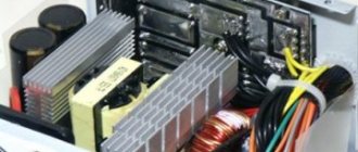
Nutrition
Electricity is supplied to the motherboard through a power supply, which is connected through a special connector. In modern types of motherboards there are two types: 20 pin and 24 pin. This is what they look like.
In some cases, four more are added to each of the main contacts to make the units compatible with different motherboards.
The first option is older; it can now be found on motherboards manufactured in the mid-2000s. The second one is relevant today and is used almost everywhere. The pinout of this connector looks like this.
By the way, by closing the PS-ON and COM contacts, you can check the functionality of the power supply.
Connecting the front panel of the computer to the motherboard
If you decide to assemble or disassemble a computer, this article will be very relevant for you. It will discuss how to properly connect the panel of front buttons and USB ports on the system unit to the motherboard. Here, I will consider not only the general appearance of the ports to which they need to be connected, but also the correct order when connecting them.
In fact, there seems to be nothing complicated about this. But in my practice, even specialists who are fairly well versed in computer technology sometimes stand in front of a system unit with a bunch of cables and think about what needs to be connected and where.
Therefore, below I will show in detail what and in what connector this or that wire needs to be connected for the correct operation of the connected front panel of the system unit. That in the future, the next time you clean your computer or perhaps replace the motherboard, it will not be difficult for you to correctly connect all the elements of the system unit to the motherboard.
It is also very important if the front panel with USB ports and outputs for headphones and microphone does not work. Then, be sure to read it to the end to find out how to fix this whole thing and return our front USB ports to working condition. Because the problem may lie in the fact that they are simply not physically connected to the motherboard.
Connecting the front panel, button block and indicators
The block of buttons and light bulbs for turning on and rebooting is connected to the motherboard using four connectors, which are connected into one continuous cable. You can see what they look like for me below. They should have approximately the same appearance for you. The main thing is to look for those connectors that have similar phrases written on them: Power SW, Power LED, HDD LED. RESTART SW.
Let's look at each connector separately:
- POWER SW (PWRBTN) - is responsible for the computer power button;
- HDDLED (+HDLED) - a hard drive light that constantly blinks when the computer is running;
- POWER LED - and + (PLED) - indicator indicating the state of the computer (on or off);
- RESTART SW (RESET) - connector responsible for the reset button;
- SPEAKER - a tweeter speaker is sometimes also present in the cable panel;
Where should all this be connected? All connectors will connect to one port, which is located in the lower right corner of the motherboard. Manufacturers usually sign them with such designations as: “F_PANEL” or simply “PANEL”. On each motherboard, near such a panel, there are small signatures where what needs to be inserted. But still, below I will give you several examples of what to add to what.
Also, sometimes an additional small speaker is connected which notifies with a squeak that the computer is turned on, as well as about various BIOS and computer hardware errors. Sometimes it is connected with all the other connectors, but as a rule, a separate four-pion connector is allocated for it.
That's it, we're done with the button block, now we can move on to the front USB and audio outputs.
System unit front panel connections
The audio and USB connectors are very similar to those we connected for buttons and indicators. But their most important difference is that they are already immediately connected into one, and when connecting you do not need to take it and connect it one pin at a time.
You can also find the place for connection at the bottom of the motherboard with labels (F_USB1, 2). There may be two or more of them on the motherboard, but it doesn’t matter which one you connect to, they will work the same. The main thing you need to do is take the connector labeled “F_USB” and put it in the appropriate connector. You can’t make a mistake, because if you try to insert it the wrong way, you simply won’t succeed, and turning it over to the other side, I think everything should fall into place.
Be sure to pay attention if you have USB 3.0 on the front panel of your computer, then you will need to connect it to the appropriate connector. You can find out where it is located in the manual for your motherboard. Also, I want to draw your attention to the fact that if USB 3.0 is connected to a standard connector, it will work, just the transfer speed will be the same as on USB 2.0.
Connecting the front audio panel to the motherboard
The situation with sound is similar to USB. Here, too, the connectors are connected into one, which will allow you to easily and without errors connect it to the motherboard. The connector itself is usually located next to the USB ports and is designated by the following abbreviations; AAFP, AUDIO, A_AUDIO.
Taking a connector with the inscription “HD Audio” or “AC 97”, we connect it to the connector with one of the signatures, an example of which I indicated above. If after connecting the headphones and microphone still do not respond, then you should check the settings of the front audio panel in the BIOS. Sometimes it happens that the system uses the “AC97” driver, but the BIOS indicates “HD Audio”, which, due to mismatch, renders our audio outputs inoperative.
On the back wall of the system unit
There are many connectors on the back of the system unit, some of which completely duplicate those located on the front. Their number can be completely different, again, it all depends on the motherboard model.
PS/2
Today this connector is considered obsolete, but on many motherboards it is still present and feels good, so to speak. Used to connect a mouse or keyboard. It is noteworthy that there are adapters from USB to PS/2.
COM port
It is almost impossible to find a COM connector on modern motherboards. Previously, it was used to connect all sorts of printers and other peripheral devices, which are now connected via USB. The COM port has an analogue - LPT, which is even less common; it has an oblong shape and is painted pink.
USB ports
As a rule, if there are 4 of these connectors in front, then at the back there are at least no less. Again, everything is done so that you can connect as many devices as possible to your computer at the same time. And if the front ports are usually occupied by all kinds of flash drives, then the rear ports are often connected to “long-lasting” devices, that is, which you will not constantly connect/disconnect. Well, for example, it could be a keyboard with a mouse, as well as printers and scanners.
There are two main types of these ports:
- USB 2.0
- USB 3.0
Of course, the third version is preferable due to its higher throughput; such a port is even marked in a different color - blue.
USB 2.0 and 3.0 are compatible with each other.
Network and Internet
One single connector is responsible for the network and the Internet - “Ethernet”, which is also sometimes called “RJ 45”. If you look closely, you will notice that there are small “windows” on this connector - these are indicators of network operation; when data is being transferred, they signal this. If the indicators do not light up, most likely the connector has stopped working and needs to be re-crimped (using a special crimp).
Video
Any monitor is connected to a computer (motherboard) using video connectors, which are located at the back. There are quite a lot of their varieties, it would not be entirely appropriate to talk about each one here, especially since the site already has a separate article about video connectors. In my opinion, only three of them can be called the most popular video ports:
- analog VGA port
- digital DVI
- digital hdmi
The rest are not so popular and are rare.
Audio
Usually - three or six inputs for connecting several speakers and a microphone. On budget segment boards, the number of audio connectors usually does not exceed three, but at the same time, all the necessary functionality is present, and this is:
- Red - for microphone;
- Green - for speakers;
- Blue - for connecting external sources, such as a TV, player or radio.
If your motherboard has six audio outputs, then know that the other three are used to connect additional speakers and a subwoofer.
USB cable wiring by color
Since there are many specifications, and the type of connector imposes its own restrictions on the placement of contacts, the pinout differs from version to version. Therefore, they must be disassembled separately.
USB 2.0 pinout
The “classic” USB 2.0 connectors have 4 pins, while the mini and micro versions have 5. In any case, data is transferred via two of them. They are usually marked on diagrams as D- and D+. They correspond to the green and white colors of the cables. Standard A and B may have gold that actually looks just yellow. Two contacts are responsible for power. A voltage of 5 V is carried out one at a time. The colors of the cables are red and orange.
Sources
- https://math-nttt.ru/novosti/kak-pravilno-podklyuchit-usb-k-materinskoj-plate.html
- https://HouseChief.ru/raspinovka-usb.html
- https://besporovod.ru/raspinovka-usb-na-materinskoj-plate-chto-gde-i-kak
- https://crast.ru/instrumenty/raspinovka-usb-na-materinskoj-plate-po-cvetam
- https://sk-impuls.ru/raspinovka-usb-na-materinskoj-plate/
- https://svetluxe.ru/raspinovka-usb-na-materinskoj-plate/
- https://tv-st.ru/ustrojstva/razem-usb-na-materinskoj-plate.html
- https://BurForum.ru/elektrika-drugoe/vhod-yusb.html
- https://odinelectric.ru/wiring/wires/shema-raspinovki-usb-kabelya-po-tsvetam
- https://my-class.ru/kak-podklyuchit-usb-k-materinskoy-plate-4-vyvoda/
- https://exsofter.ru/raspinovka-usb-na-materinskoj-plate/
- https://veranda71.ru/raspinovka-usb-na-materinskoj-plate/
- https://GeshTV.ru/devajsy/podklyuchenie-yusb-k-materinskoj-plate.html
- https://LesSale.ru/glavnoe/podklyuchenie-provodov-usb-k-materinskoj-plate.html
- https://sib-bastion.ru/novoe/yusb-na-materinskoj-plate.html