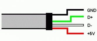
4-Pin computer cooler pinout
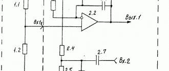
Electrical diagram of a 4-Pin cooler
As befits such a device, the fan in question has an electrical circuit. One of the common options is shown in the image below. Such an illustration may be needed when resoldering or reworking the connection method and will be useful to people who understand the structure of electronics. In addition, all four wires are marked in the picture, so there should be no problems reading the diagram.
Pinout
If you have already read our other article on the topic of pinout of a 3-Pin computer cooler, then you may know that black indicates ground, that is, zero contact, yellow and green have a voltage of 12 and 7 Volts, respectively. Now we need to consider the fourth wire.
The blue contact is the control one and is responsible for adjusting the speed of the blades. It is also called a PWM contact, or PWM (pulse width modulation). PWM is a method of controlling load power, which is carried out by applying pulses of different widths. Without using PWM, the fan will rotate constantly at maximum power - 12 Volts. If the program changes the rotation speed, the modulation itself comes into play. Pulses with a high frequency are supplied to the control contact, which does not change, only the time the fan is in the pulse winding changes. Therefore, the equipment specification specifies the range of its rotation speed. The lower value is most often tied to the minimum pulse frequency, that is, in their absence, the blades can spin even slower, if this is provided for by the system in which it operates.
As for controlling the rotation speed through the modulation under consideration, there are two options. The first occurs using a multicontroller located on the motherboard. It reads data from the thermal sensor (if we are considering a processor cooler) and then determines the optimal fan operating mode. You can configure this mode manually through the BIOS.
The second way is to intercept the controller with software, and this will be software from the motherboard manufacturer, or special software, for example SpeedFan.
The PWM contact on the motherboard can control the rotation speed of even 2 or 3-Pin coolers, only they need modification. Knowledgeable users will take the electrical circuit as an example and, without any special financial costs, complete what is necessary to ensure the transmission of impulses through this contact.
Connecting a 4-Pin cooler to the motherboard
There is not always a motherboard with four contacts for PWR_FAN, so owners of 4-Pin fans will have to be left without the speed control function, since there is simply no fourth PWM contact, as a result of which the pulses have nowhere to go. Connecting such a cooler is quite simple, you just need to find the pins on the system board.
As for the installation or dismantling of the cooler itself, a separate material is devoted to these topics on our website. We recommend that you familiarize yourself with them if you are planning to disassemble your computer.
We did not delve into the operation of the control contact, since this would be meaningless information for the average user
We only outlined its importance in the overall diagram, and also carried out a detailed pinout of all other wires
Schematic electrical diagrams, connecting devices and pinouts of connectors
Every home has a lot of computer fans: CPU coolers, video cards and PC power supplies. They can be used to replace burnt ones, or they can be connected directly to the power supply. There can be many applications for this: as a blower in hot weather, ventilating the workplace from smoke during soldering, in electronic toys, and so on.
Fans usually come in standard sizes, with 80mm and 120mm coolers being the most popular today. Their connection is also standardized, so all you need to know is the pinout of the 2, 3 and 4 pin connectors.
On modern motherboards based on the sixth or seventh generation of Intel processors, as a rule, only 4 pin connectors are soldered, and 3 pin connectors are already a thing of the past, so we will see them only in older generations of coolers and fans. As for the location of their installation - on the power supply unit, video adapter or processor, this does not matter at all since the connection is standard and the main thing here is the pinout of the connector.
Connecting computer cooling fans: all about connectors
Case fans are divided by size, type of bearings, number of revolutions, and even by method of application. Some are designed to create static pressure, while others are designed for good air flow in the case. And the most interesting thing is that the same fan can be connected using different connectors. Some of them can regulate the speed, while others work at full speed. This affects the comfort when using the computer. To choose the right fan, it is worth at least superficially studying the features and nuances of the connection.
Why are there so many connectors?
A little history
When the computer first appeared and was called a computer, transistors were the size of a matchbox, and the computer itself reached the size of a room and even an apartment. If it was necessary to cool such a colossus, then huge industrial hoods were used for this, so no one even mentioned noise and comfort. It’s a different matter when the global and formidable “computer” was trimmed, combed and tinted to make a “computer”.
A little later, the serious invention was completely glamorized and began to be affectionately called a personal computer. Thanks to Apple: they had to do a lot to turn the bulky monster into an attractive device for buyers. Other companies, such as IBM, for example, have also achieved something on this front.
These developments in the race for personality were unified and standardized so that we got computers as they are now.
The reduction in parts was followed by a reduction in body size. Matchboxes turned into matches, and later into a tenth of their size. This, as well as an increase in power characteristics, was the first thing that required good cooling.
But it’s one thing to cool a computer in noisy work buildings, and another thing to cool a powerful compact computer on a schoolchild’s desk.
Previously, stability and reliability were prioritized. Well, it buzzes - so be it. Even the most ancient computer models cannot boast of a good cooling system.
A standard cooler on the processor, a humming power supply with an eightieth fan and a couple of no-name turntables in the case, connected either to the motherboard or directly to the 12 V line. If only it worked. And no speed control. You turn it on, get used to the noise of the vacuum cleaner - and you work. Why, even Quake and Unreal went crazy with this noise. But, as we know, desires grow, and so do demands.
Connecting the fan to the power supply
All you need to have for this operation is a thin screwdriver or tweezers, you may also need pliers, but this is optional.
We take in our hands the part of the adapter to which the wires from the Molex are connected. In this PCPlug connector we see contacts in the form of pins. This is the input of the adapter. It is this side that the adapter connects to the power supply.
As you can see, to prevent the contact pins from falling out of the connector, they are held in place by two “wings”. The pins themselves are rolled from an aluminum plate and are empty inside. They have special wings on both sides, bent in a herringbone pattern, so that they allow you to insert the pin into the connector, but not pull it out. We need to use thin tweezers or a screwdriver to bend these wings inward so that the pins can be pulled out of the connector. We need to swap the places of the black wire, which is next to the yellow one, to which the black wire from Molex and the outermost red wire are suitable.
After you pull out these two contacts, bend the wings back and insert the red wire in place of the black one, and the black wire in place of the red one. Make sure the contacts don't pop back out. All! Now the voltage on the Molex is 7 Volts.
The stated fan speed, air flow and noise level are specific to 12V power supply only. This cooler has a Molex connector. Test system:
- Processor: AMD Duron 650Mhz (launched at 650 and 748Mhz);
- Motherboard: Giga-Byte GA 7IXE4 (AMD 750 chipset);
- Memory: 128Mb PC100 SDRAM;
- Video card: ASUS v3800PRO tv in/out;
- LMD: 13.6Gb Fujitsu MPE 3136AH;
- Sound card: Creative Sound Blaster Live! Value;
5
Now unscrew the fan from the power supply
. It is secured with four bolts. You need to choose a cooler that is exactly the same size. You can do this at a computer hardware store without any problems.
The color markings on the wires that go to the power supply are different. Red wire: +5V. Black – common wires (connected to GND connectors). Yellow: +12V.
The red fan is connected to the +12V power supply (yellow power supply wire), and the black one is connected to the +5V power supply (red power supply wire). In this case, a voltage of 12V - 5V = 7V is supplied to the fan. It will work normally if the initial voltage for this particular fan is less than 7 V. If it is more (I have seen fans whose initial voltage was in the range from 9 to 11 V), then the fan will periodically twitch in attempts to start.
The yellow fan wire remains unused, since in this situation the speed sensor signals remain unclaimed.
System tuning - reducing noise in the power supply
Author: Anton Lennikov Corrections and comments: Stanislav Vasiliev When the temperature outside approaches fifty degrees in the sun, it seems not very timely to talk about reducing computer noise. Provide it with complete cooling. On the other hand, Apple once released an excellent system, the so-called G4 Cube, which was not equipped with fans at all. The essence of the idea was in the exploitation of physical laws, that is, the concept that cold air, sucked in due to the temperature difference from below, heats up as it passes between the PC components, and for the same reason, rising up, leaves the case. Unfortunately, for a number of reasons, the “cubes” were discontinued and are no longer sold, and modern PCs set all imaginable records for noise.
Standard ATX power supply
If you've ever lived in the same room with a computer and tried to leave it running overnight, then talking about reducing noise is far from an empty phrase for you. In this article we will talk about one of the ways
make your PC quieter. Before you start reading this material, we warn you that the author does not bear any responsibility for what may happen to the reader’s computer if he tries to follow the advice given in this material. The text is only a reference guide, but not a guide to action. And remember that overheating leads to a reduction in the life cycle of both the PC as a whole and its individual parts.
It's no secret that in the average desktop PC, it is the power supply fan that makes the loudest noise. It is also curious that in theory, a fan is not needed at all for the power supply to operate, but in practice, this PC part actually gets hot and needs effective airflow. The main thing you need to understand is that effective airflow and noisy airflow are fundamentally different things. In addition, the power supply fan, as a rule, is never cleaned of dust, and can resonate with 2 cases at once, the case of the unit and the computer. We will tell you how to deal with resonance in a separate article.
So, there are only 2 ways and a lot of options on how you can reduce noise and at the same time maintain the normal temperature of the unit.
Remove the fan and remove the power supply cover.
In this case, the temperature inside the case will increase slightly, usually no more than 2-3 degrees. At the same time, practice shows that everything can function normally, because the power supply has 2 of its own radiators. As a result, the noise level will be significantly reduced. This method has a significant drawback: the active elements of the power supply will be open and may short out something. Therefore, it makes sense to be very careful to ensure that the exposed elements of the power supply (i.e. those that would normally be hidden by a casing) do not come into contact with anything.
Opened ATX power supply, note two heatsinks
In addition, we cannot recommend such a solution for hot systems based on AMD processors. An open power supply is best used where the absence of noise is critical, for example, in home network file servers installed in a residential area based on Intel Celeron, Pentium III and 4 processors. They also often use passive processor cooling.
Editor's comment:
I've used this method on several PCs. Sometimes the temperature inside the system when the power supply is open without a fan increases significantly, that is, by 5 degrees or more. In addition, in one of the experiments with a system based on a Pentium 4 2.2 GHz processor, as a result of turning off the fan in the power supply, the noise exceeded the initial value. The reason for this was the fan on the processor, which rotated slowly in the basic mode, and spun up to maximum speed as the temperature increased. If it was considered normal for an “unconfigured” system to run office applications at a temperature of 38/39 degrees Celsius on the board/processor, then when the power supply was turned off, the temperature increased by almost ten degrees for both values. In addition, the stability of the system has noticeably deteriorated, especially in resource-intensive and gaming applications. By setting the fan in the power supply to a slower operating mode, these problems were resolved. Subsequently, a different cooling method was used for this system. More comprehensive and complex, it made it possible to ensure noticeably quieter PC operation.
We will not describe in detail the process of “tuning” the system by removing the cover, since there is nothing complicated in unscrewing six bolts and removing the cover from the power supply. If this is still difficult for you, ask more experienced friends for help or read the first part of the next chapter.
We unscrew four of these bolts on the power supply cover and you’re done...
Summary:
Advantages:
- Complete absence of noise (from power supply)
- Ease of execution.
- Does not require financial costs.
Flaws:
- The power supply elements that are energized are open.
- The power supply can still overheat in a cramped case
- Together with the power supply, the entire system may overheat
Switch the power supply fan to 5 volts
This is easy to do even in those power supplies where the fan wires are soldered to the main board. The standard power supply has a regular 12 volt fan with dimensions of 80x80 mm, which can be turned off and replaced with a similar or thinner and slower 80 mm fan, which, in turn, can be changed to 5 volts.
Standard 80mm fan in power supply
The standard power supply has four-pin female and male connectors with the following wiring:
Pinout of standard PC connector
Unsolder or disconnect the fan from the main board of the power supply. The fan is connected in conventional power supplies with two wires, in units from PowerMan and a number of other manufacturers that have built in a cooler rotation speed control module with three. As a rule, if the fan is connected with two wires, one of them is red, the other is black. If the power supply has its own control system, then you should not violate it. The only way to reduce noise in this case is to turn off the fan altogether. However, practice shows that this is unreasonable. At least if you leave the power supply inside the PC.
Then, using the photo above, connect the red wire to +5 and the black wire to nearest ground. Thus, the fan will operate at 5 volts and spin noticeably slower. As a result, its noise will decrease. A more correct option is to wire the fan contacts to a similar block. If you are a thorough person, then you should do without twists and tape.
A. With the installation of a new fan.
Unscrew 4 screws and remove the fan from the power supply.
Preparatory stage.
You need to buy a standard 8 cm fan for the system unit and convert it, as described above, to 5 volts. To do this, you need to remove all the wires from the sockets except the yellow one, it is already installed correctly. Then the black wire from which the black fan wire comes off must be put in place of the red one. When finished, only 2 wires, yellow and black, should remain in the socket. There is an article on the website www.hardwareportal.ru that describes in detail methods for reducing fan voltage. Don't forget to test the design.
Buy a new fan
Before disassembling the power supply, in addition to a Phillips screwdriver, arm yourself with a brush (or a vacuum cleaner), in general, something with which you can clean the power supply from accumulated dust. And also scissors and electrical tape.
This is just a little dust. If your building is two years old, then everything inside is much worse
Let's get started.
Disconnect the power supply from the computer, first turning off everything. Remove the cover, which is attached to 4 small cross bolts. Clean the power supply from dust.
Then, you need to find 2 wires going from the power supply fan to the board, red and black, and carefully cut them closer to the place where they are soldered. Wrap the remaining wires with electrical tape. If there is no electrical tape, then cut off the wires as close to the board as possible (as in the photo).
Cut the wires closer to the board if there is nothing to insulate with
The main thing is that the wiring is not short-circuited. After this, the fan is removed, which can then be used as an exhaust hood for the case. Instead of the standard one, a new, just purchased fan is installed. By the way, when choosing a replacement, look for fans with the inscription “ball bearing”, that is, on a ball bearing. These fans are quieter and last longer than their cheaper counterparts.
The main thing you have to decide is where your fan will work - to blow air out or to blow it in. On the one hand, when blowing, cooling is more efficient, since the temperature of the air supplied at high speed from the outside is noticeably lower than the temperature inside the PC. On the other hand, in this mode the power supply works like a vacuum cleaner, constantly drawing both inside itself and inside the PC a lot of dust, which, by the way, has excellent electrical conductivity.
In addition, the power supply unit is usually installed at the top of the PC, and working as a blower, it pulls warm air from the case as well. Most fans have the direction of air movement marked on the case. In any case, it’s easy to check where the flow is going - just connect the fan to the power supply.
Secure the structure well. Now you can close the lid and return the power supply to its original place. The finished design looks like this:
The wires can be routed either through the ventilation slots (see photo) or through the gap between the housing and the casing, in the corner. We connect the fan to a free outlet and turn on the system. (At the 2nd output of the fan, where there is already 5 volts, you can connect the fan that we removed from the power supply or any other).
It is better to check in advance whether the fan is working or not. After installation, monitor the power supply and its temperature conditions for several days. If overheating does occur, the power supply case will be hot, and a characteristic smell of burnt electronics will appear, return everything to its place. Of the 10 cases where we had to do this, overheating was never observed.
Summary:
Advantages:
- Ease of implementation.
- Additional fan.
- Low noise.
- Guaranteed sufficient heat exchange of the power supply.
- The elegance of the solution.
Flaws
- You need to buy a fan.
- The noise still remains, although it becomes much quieter.
B. Use of resistance
This method has been discussed many times in conferences. Its essence lies in the fact that a constant resistance or variable resistor is soldered onto the red wire. In this case, you can independently adjust the noise-cooling ratio. However, this method has a number of disadvantages: firstly, you need to find a suitable resistance resistor, secondly, you have to solder, which many lazy “enthusiasts” who tend to do everything according to the “once and done” principle do not really like, and thirdly, the resistance gets quite hot in during operation, and additional heat in the power supply where we already reduce the efficiency of the cooling system is completely useless.
Summary:
Advantages:
- Cheapness. (resistance resistors cost within 10 rubles.)
- Elegance of execution. (no need to run wires or occupy an outlet)
- Low noise.
Flaws
- The noise still remains, although it becomes much quieter.
- You need to find a suitable resistance.
- A soldering iron and skills to work with it are required.
- The resistance heats up during operation.
Malfunctions
If after these operations the computer does not turn on at all, then first check whether you have connected the power, whether the unit is well connected to the motherboard, if this does not help, try to put everything back in place and try to start the system. If this does not help, then take the power supply for repair. You probably damaged the electronics during the upgrade. To be fair, it should be noted that none of the above requires special higher education, and a fatal outcome is unlikely, especially if everything was done carefully.
Risk factor
In the worst case, you will lose a power supply that costs about $20, in the best case, $30. After carrying out the manipulation, it is not difficult to cover up the traces of the intervention and get a new unit under warranty, if of course there is one.
Editor's comments
First of all, I would like to note that the most correct thing would be not to torture your old power supply, but to buy a new one with adjustable fan speed. Such models are also sold in Russia, although finding them in stores will be very difficult. We wrote about similar solutions in a report from the spring CeBit 2002.
High-quality power supply with fan speed control
A separate set of fans for installation in a PC or its power supply
Alternatively, you can apply the concept adopted by most laptop manufacturers to the desktop PC. To prevent the portable system from heating up, as well as for a number of other reasons, the power supply is moved outside. A similar method was used in the PowerMac G4. But, to implement this method, you will need much more than electrical tape and a soldering iron, and only a competent and experienced person can decide on this. Simply put, the power supply is reassembled in another case, the wires from it are diverted into the PC. The PC itself is carefully insulated and some work is done on the tin.
Some users try to ensure natural air flow inside the PC at home by closing some holes and drilling others. But that's a completely different story. If you have a similar experience and are ready to describe it, write to
Additional materials
Comparison of coolers for P4. Q4 `2002 Comparison of coolers for the SocketA connector. Q4 `2002 Comparison of coolers for P4. Q3 `2002 Comparison of coolers for the SocketA connector. Q3 `2002 Comparison of coolers for the SocketA connector. Q2 `2002 “Master” of cooling Badong Encyclopedia of processor coolers Testing thermal pastes Coolers with aluminum fans. Titan vs Spire Advanced processor cooling technologies TMD fan from YS Tech Testing system fans Review of the Fanner PC Vent II system cooler Computer thermometer based on DS18S20
PSU connectors
The power supply contains the main connectors (electrical connectors) previously used in old power supplies, supplying voltages of 3.3, 5 and 12 Volts. Each connector pin is one Pin.
Motherboard
connects to the power supply via a 24 Pin male connector (the so-called bus), which has undergone changes with the improvement of motherboards. Previous generations of motherboards were connected to the power supply via a 20 Pin bus.
Because of this, in order to support any type of connection to the motherboard, the connector is made in the form of a collapsible design with a 20 Pin main and 4 Pin additional power connector.
If the motherboard only needs 20 Pin, the 4 Pin connector is removed (pull down along the plastic rails) and bent to make it easy to install a 20-pin bus.
Molex 8981 connectors are used to power optical drives and other drives with a PATA (Parallel ATA) connection interface.
(by the name of the developer-manufacturer company).
SATA (Serial ATA) connection interface
for storage devices of all types.
Typically, to power storage devices
, the power supply has two special 15 Pin connectors (or there is an adapter for powering PATA HDD - SATA HDD).
Advice!
You can also connect a modern hard drive via molex, but connecting via SATA and molex at the same time is not recommended, since the HDD may not withstand the load and burn out.
Central processor
Requires power supply from a 4 or 8 Pin connector (can be detachable).
Video card
You need 6 or 8 Pin power. The connector can be dismountable to 6+2 Pin
Some modern power supplies may contain an outdated 4 Pin connector for floppy drives
, card readers, etc.
Also 3 and 4 Pin connectors are used to connect coolers
.
Foreboding
Is the fan in the computer power supply making noise? This event causes a lot of indignation from users who begin to count the costs of purchasing a new cooler. It is at this stage that there is no need to rush, the fact is that noise is not a breakdown. This is a signal to the computer owner that there are some difficulties with the fan that need to be corrected immediately. Everything is quite simple here:
- the power supply is removed and disassembled and blown away from dust;
- the fan is unscrewed and removed;
- remove the protective sticker on the cooler rotor, pour 3-4 drops of oil inside;
- the sticker is returned to its place, the power supply is assembled and installed in the computer.
The algorithm is quite simple, but very effective. There may be problems with a sticker that has lost its adhesive properties. There is no need to install it in this form; it will still fall off and rattle inside the case. It's better to install a new sticker. Where to get? Cut it out of thick tape, use a chewing gum insert, or purchase any children's sticker of similar sizes in the store.
Types of cooling systems for connecting to the motherboard
Cooling units vary not only in color and size, but also in functional purpose. Basically, there is a division into processor coolers that cool the CPU in direct contact.
Next come the case fans, which were discussed above: they regulate the air flow itself passing through the system unit, and can also indirectly or directly cool individual elements of the computer.
And also don’t forget the water pump fans, which remove heat from the radiator of this device.
All of them are connected to the motherboard and controlled through it using BIOS, UEFI or operating system utilities.
Let's start with the most important fans, without which the system will be impossible to operate or will cause extreme discomfort.
Option 1: CPU cooler
The absence of a cooler on the CPU can lead to rapid overheating of this element; in addition, some BIOS subsystems will not even allow you to start loading the operating system without a cooling system installed. Connecting it to the motherboard is quite easy; you need to correctly mount it on the CPU and connect the pin wire to the appropriate connector, which is labeled on the board as follows: “CPU_FAN”.
Even for tower coolers with dual fans, one connector is enough, since such devices are equipped with a special connector that connects two fans so that they are powered via one wire.
Read more: Installing and removing a processor cooler
This is the most correct way to connect processor coolers. Of course, if you wish, you can connect them to other connectors, which will be discussed later, but then the required voltage and level of speed control will not be guaranteed. However, in models like the Cooler Master MasterAir MA620P, where there is the ability to use 3 fans, not to mention the fanciful solutions of enthusiasts, the need for connectors will only increase; such demand can be satisfied by a good motherboard with a focus on gaming.
Option 2: Case fan
Next in importance are the fans of the entire computer. Most often there are two of them - for air injection and for air exhaust - usually this amount is enough for normal PC operation without extreme loads
To install the devices, mount them on any suitable location on your computer case, then connect the wire coming from the cooling element to the connector on the motherboard labeled “CHA_FAN” or “SYS_FAN”. In this case, at the end there should be a number from “1” to the maximum number of fans that can be connected to your motherboard, including alphanumeric designations like “4A” or “3B”.
Such fans, depending on the design features of the case, can be located on the front, rear, or side cover; in addition, there are options for blowing hard drives and other system components. At the same time, you choose how this or that fan should function: by pumping air into the system unit in a certain place or, conversely, by removing it.
Option 3: Water pump fans
Water pump fans stand apart from others. It should be clarified that their number can range from 1 to 3 pieces, depending on the length of the radiator in maintenance-free water/liquid cooling systems, as well as the circuit for users in custom ones. They are connected so that they are powered from one wire, but they can also be disconnected to provide each fan with its own connector. It is necessary to separate the connection of unattended SVO and custom ones. In the case of the former, their fans should be connected in the same way as regular air fans, into the “CPU_FAN” connector.
It is better to connect custom LSS to specialized connectors labeled “W_PUMP”, “W_PUMP+” or “PUMP_FAN”, which supply higher voltage.
This article discussed common cases of connecting various types of cooling systems to the motherboard. Most often, connecting one to the other is very easy, and the connectors are labeled accordingly: “CPU_FAN”, “CHA_FAN” / “SYS_FAN” or “W_PUMP” / “PUMP_FAN”, however, it is worth understanding them and not confusing them, which can lead to failure fans or their controllers. We are glad that we were able to help you solve the problem. Describe what did not work for you. Our specialists will try to answer as quickly as possible.
Did this article help you?
- https://2shemi.ru/raspinovka-kulera-podklyuchenie-3-pin-i-4-pin-ventilyatora/
- https://infotechnica.ru/pro-sborku-i-podklyucheniya/raznyie-kulera-k-materinskim-platam/
- https://lumpics.ru/how-to-connect-a-fan-to-motherboard/
Basic fan requirements
Having understood the methodology for choosing a worthy product on the computer components market, it’s time to move directly to the requirements. The noise level should not exceed 20 decibels. This is a very important factor, because this indicator is a certain hearing threshold. As for the impeller rotation speed, it all depends on the quality of the assembly. There are models that spin the fan silently at a frequency of 2000 rpm. However, experts recommend limiting yourself to 1200 rpm.
Many users have already heard many times that all the fans in the system come into resonance, which causes an eerie hum in the system unit and the case begins to rattle. Oddly enough, the computer's power supply may also be involved. The fan in it twitches not only due to a malfunction. The problem may also be that the impeller rotation speed is too high. Also, cheap Chinese fans have a problem with the rotor being skewed, which is why a constant knocking sound is heard during the operation of the device, and the cooler itself begins to twitch.
Connection procedure
Turn off the power to the computer
Simply turning off your PC using a button is not the best solution. It must be completely isolated from the electrical network, that is, unplug it from the socket or turn the switch to the “off” position.
Secure the cooler in place
To do this, you need to dismantle the side cover, install the fan in the place intended for it and secure it with bolts
It is necessary to pay attention to the indicator of the direction of rotation of its impeller (arrow on the end of the cooler). Depending on how the fan is positioned, airflow can be directed either inward (pull) or out of the computer. And this directly affects the cooling efficiency of the system unit electronics
To avoid mistakes, it is advisable to replace the cooler one-to-one, so it is not advisable to remove the faulty one before purchasing a new one.
Connection to power supply
The author does not know which fan the reader will install to replace the failed one. This may be a used product from another computer or purchased, but they all come in various modifications. Therefore, only possible options are considered below.
The photo shows the pinout of cooler connectors depending on the number of contacts. If their number does not match the computer's power supply pins, you will have to use adapters. In brackets is the color designation of the conductors according to the second option.
Wire marking
- +12 V – Kr (Zhl).
- -12 V – always black.
- Tachometer line – Zhl (Green).
- Speed control - blue.
Pinout of the computer power supply Pinout of the cooler connector
If the fan is quite noisy, then it can be powered not by 12 V, but by seven (connection to the outer terminals) or five (to the red one). The ground wire, as noted above, is always black.
Some articles give recommendations for changing the speed of rotation of the impeller using limiting resistors. Their power is about 1.2 - 2 W, and the dimensions are appropriate. It’s not quite convenient anymore. In general, this is understandable. But what criteria should be used to select the resistance value if the user with electrical equipment is, at best, only “you”? And at worst - nothing.
The author advises not to experiment and, if desired, to include a diode in the circuit. Regardless of the type, it is sure to provide a certain voltage drop on the order of 0.6 to 0.85 volts. If you need to reduce the rating even further, you can use 2 - 3 semiconductors in series. To do this, you do not need to engage in engineering calculations or consult a specialist.
Fun math
It’s better to start not with choosing a specific model or brand, but with the technical requirements that apply to the fan. Yes, such a simple computer component has a number of limitations that the user will have to put up with, because the user’s comfortable work at the computer depends on the right choice. It follows that the basic requirements are noiselessness and efficient airflow.
In most cases, the computer power supply cooling fan cannot independently regulate the speed of the impeller. By supplying 5 volts to the cooler, the power supply uses the maximum rotation speed that is characteristic of this voltage. This is where things get interesting, because the characteristics for all fans are indicated for a 12-volt line. There are few options here - trust your instincts or the recommendations of experts, because it is impossible to accurately calculate the behavior of the impeller mathematically.
Cooler pinout: connecting 3 pin and 4 pin fans
Every home has a lot of computer fans: CPU coolers, video cards and PC power supplies. They can be used to replace burnt ones, or they can be connected directly to the power supply. There can be many applications for this: as a blower in hot weather, ventilating the workplace from smoke during soldering, in electronic toys, and so on.
Fans usually come in standard sizes, with 80mm and 120mm coolers being the most popular today. Their connection is also standardized, so all you need to know is the pinout of the 2, 3 and 4 pin connectors.
On modern motherboards based on the sixth or seventh generation of Intel processors, as a rule, only 4 pin connectors are soldered, and 3 pin connectors are already a thing of the past, so we will see them only in older generations of coolers and fans. As for the location of their installation - on the power supply unit, video adapter or processor, this does not matter at all since the connection is standard and the main thing here is the pinout of the connector.
4 pin cooler wire pinout
Here the rotation speed can not only be read, but also changed. This is done using an impulse from the motherboard. It is capable of returning information to the tachogenerator in real time (the 3-pin one is incapable of this, since the sensor and controller are on the same power line).
3 pin cooler connector pinout
The most common type of fan is 3 pin. In addition to the negative and 12 volt wires, a third, “tacho” wire appears here. It sits directly on the sensor leg.
- Black wire - ground (Ground/-12V);
- Red wire - positive (+12V);
- Yellow wire - revolutions (RPM).
2 pin cooler wire pinout
The simplest cooler with two wires. The most common colors: black and red. Black - working negative of the board, red - 12 V power supply.
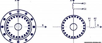
Here the coils create a magnetic field, which causes the rotor to spin within the magnetic field created by the magnet, and the Hall effect sensor evaluates the rotation (position) of the rotor.
How to connect a 3-pin cooler to a 4-pin
To connect a 3-pin cooler to a 4-pin connector on the motherboard in order to be able to programmatically adjust the speed, use the following diagram:
Useful: DIP chip packages
When a 3-wire fan is directly connected to a 4-pin connector on the motherboard, the fan will always rotate, because the motherboard will not have the ability to control the 3-pin fan and adjust the speed of the cooler.
Connecting the cooler to the power supply or battery
To connect to the power supply, use standard connectors, but if you need to change the number of revolutions (speed), you just need to reduce the voltage supplied to the cooler, and this is done very simply by rearranging the wires on the socket:
This way you can connect any fan, and the lower the voltage, the lower the speed, and therefore the quieter its operation. If the computer does not get very hot, but is very noisy, you can use this method.
To power it from batteries or rechargeable batteries, simply connect the plus to the red wire and the minus to the black wire of the cooler. It starts to rotate at 3 volts, the maximum speed will be somewhere around 15. You cannot increase the voltage any more - the motor windings will burn out from overheating. The current consumption will be approximately 50-100 milliamps.
PC cooler design and repair
In order to disassemble the fan, you need to remove the sticker on the side of the wires, opening access to the rubber plug, which we remove.
https://youtube.com/watch?v=_rB3ZHcTBzY
We pick up the plastic or metal half-ring with any object with a sharp end (a stationery knife, a flat-head screwdriver, etc.) and remove it from the shaft.
The view reveals a motor operating on direct current using a brushless principle.
An all-metal magnet is attached to the plastic base of the rotor with an impeller in a circle around the shaft, and a magnetic circuit on a copper coil is attached to the stator.
Then clean the hole under the axle and drop a little machine oil there, put it back together, install a plug (so that dust doesn’t get clogged) and continue using the much quieter fan.
All such fans have a brushless rotation mechanism: they are reliable, economical, quiet and have the ability to adjust the speed.
In modern coolers, the connectors are much smaller, where the first contact is numbered and is “minus”, the second is “plus”, the third transmits data about the current rotation speed of the impeller, and the fourth controls the rotation speed.
18— 4.56 Loading…
CLICK HERE AND OPEN
Connecting a case fan
Having determined the appropriate connector, connect the turntable plug. The frame of the device is pre-fixed in the designated location of the system unit. Modern boards have four-pin combs, but old samples with only three outputs are still used (No. 4 in the bottom photo). A device powered from a connector where there is no fourth line necessary to adjust the impeller speed will always operate at standard speed. The cooling devices themselves can also have a three-pin plug - both case and processor (No. 3 in the second photo). There will be no control or feedback options in this situation either.
Gaming boards usually have several connectors for system turntables, and there are separate rows of connectors for water cooling with increased voltage.
The principle of operation of a quenching capacitor for connecting a fan from a computer to 220 volts
Before we calculate a specific example, let's say a few words about how a quenching capacitor works in an alternating current circuit. Essentially, in this case, the capacitor works as it should. At the first half-wave, it charges, passing current and voltage. Then after charging it just "closes". Although the half-wave is not yet completed. In this case, the power supply for subsequent radioelements is limited. Further, with a reverse half-wave, everything is in the same order, but the direction of current flow and voltage through the capacitor occurs in the opposite direction. As a result, this is how voltage and current limitation occurs. The capacitor simply closes at a certain point, that's all. In fact, its closure will depend on the resistance of the consumer, on the capacitance of the capacitor, on the frequency of the alternating current. We won’t delve into the wilds, but will immediately present the final formula. Here she is.
C(uF) = (3200*I(load, A))/√(Uinput²-Uoutput²)
Let's explain the values in the formula
3200 is the proportionality coefficient, I is the current consumed by the load, Uin is the mains voltage (220 volts, although this may be less if you use a step-down transformer), Uout is the supply voltage of the load (lamp). Now that we understand what and where it comes from, let’s try to analyze the case for a specific example
conclusions
Connecting fans to the motherboard is important both for stable operation of the computer and for extending the life of components. Mounting equipment and finding connectors (plugs) is not difficult even for novice users. To figure out how to connect a fan to the motherboard, you do not need special knowledge and skills - you just need attentiveness and accuracy.
Rate this article:
( 2 ratings, average: 3.00 out of 5)
Tweet Pin It
PC cooler design and repair
In order to disassemble the fan, you need to remove the sticker on the side of the wires, opening access to the rubber plug, which we remove.
We pick up the plastic or metal half-ring with any object with a sharp end (a stationery knife, a flat-head screwdriver, etc.) and remove it from the shaft. The view reveals a motor operating on direct current using a brushless principle. An all-metal magnet is attached to the plastic base of the rotor with an impeller in a circle around the shaft, and a magnetic circuit on a copper coil is attached to the stator.
Then clean the hole under the axle and drop a little machine oil there, put it back together, install a plug (so that dust doesn’t get clogged) and continue using the much quieter fan.
In modern coolers, the connectors are much smaller, where the first contact is numbered and is “minus”, the second is “plus”, the third transmits data about the current rotation speed of the impeller, and the fourth controls the rotation speed.
Cooler design or how does the blower fan work?
So, there is a computer, which means there is a cooling system for some components. Including active, which involves a number of devices for forced heat removal. This means that at least several noisy fans in the computer are guaranteed. You know what types of fans for blowing electronic components are from the article Cooler: basic concepts. Now we are talking about its filling.
Where can you find the widest selection of fans for your computer or laptop? AliExpress offers the widest selection of coolers, including for any video card and a single radiator. With this choice, you can put ANY device inside your PC under cooling. Why overpay the “sellers” if you can buy the same thing right now, just by waiting a little? See for yourself right now
Lubrication
Having determined that replacing the computer power supply fan is not necessary, it will not be difficult for the user to take steps to clean and lubricate the cooler. However, there is one factor that all readers should pay attention to. We're talking about lubrication. The fact is that the hum during operation is not produced by the fan blades, but by the bearing, which, when dry, begins to distort the movement of the rotor.
The user should only use fluid oils that are capable of lubricating the bearing. However, we should not forget about high viscosity, because the lubricant must remain inside and not leak out under the influence of centrifugal force. Here it is better to use lubricant for sewing machines (analogous to the I-8 brand). In extreme cases, machine oil will do.
Replacing the cooler is the best solution
If you have never changed the cooler on a power supply before, it is better to trust the professionals in this matter.
Only a specialist can carry out the replacement quickly and efficiently.
ready to help you solve this problem. Similar procedures in our service center include the following work:
- Removing static and disassembling the system unit;
- Removing fasteners and dismantling the cooler;
- Assessment of its performance, attempts to restore it;
- Device replacement;
- Assembling a computer and testing the operation of the replaced element.
Why do you have to change the cooler?
Coolers on power supplies are truly the most important part of them. PSUs tend to run hotter than many other PC components, so cooling them is a critical issue.
At the same time, most often user complaints are related precisely to the fact that their fan on the power supply does not work. Not on the processor, not on the video card, but on the power supply. Why is that? The reasons are as follows:
All these reasons combined lead to the fact that your fan on the power supply does not work. But what to do in such a situation? The answer is quite simple.
From theory to practice
Having figured out which fan is in the computer power supply, the user can only buy its analogue and replace it. True, a small surprise awaits the owner here. We are talking about an interface for connecting to the power supply. Almost all fans are sold with a 4-pin connector, but on the power supply board there are only two contacts, plus they are soldered. There is no need to be upset, in most cases there is dummy soldering on the board. In fact, two wires from the fan are just covered in glue.
Cleaning the computer power supply by our specialists
Using a small screwdriver or a pin or something thin enough to accommodate the small tabs that hold the cable in place.
The tabs must be in the position shown below to pull the cable out. Wrap the fan cable around the base of the removed clip, which should be thinner. Make sure you don't wrap too much or you won't be able to reinsert the power cord. If you make a couple of windings, you won't need to use a pond to weld the two wires together. pushing out from the inside with a regular screwdriver. Naturally, after unscrewing the cooler from the PSU case, you need to carefully remove the glue from the contacts (you may need a knife). At the end of the cleaning procedure, the user will see a board with two pins. The main thing here is to remember where the plus is (red wire) and where the minus is (black wire). Then it’s a matter of technique: you need to put the 4-pin connector on these two contacts so that the polarity matches the color of the cables. And there is nothing wrong with the fact that two contacts remained unconnected.
Insert the two connected wires, making sure there are no threads that are exposed by the plastic connector. Also make sure you install the cable correctly by pulling and trying to pull it out. In many stores, when you ask for a fan, they will cut the fan with so much heatsink attached. This may seem like a joke, but our species with high temperatures in the summer tend to overheat very easily. Luckily, there are a number of actions we can take to keep our device cool.
Most of the hot air comes out of the back of the device, so it is important not to stick this area to the wall or furniture and, above all, not to insert objects that prevent proper ventilation. Otherwise, the hot air emitted by the device will remain in circulation, creating additional overheating and almost certain damage.