Pass-through switch circuits allow you to turn lighting on and off from two or more different locations. In some cases this is not just convenient, but also very necessary.
For example, there is a long corridor in the room. It is naturally illuminated. By turning on the light at the beginning, and having this same connection diagram for the pass-through switch , you will not have to return again to turn it off, but you can do this with the second switch, which is installed at the other end of the corridor. Very often, such circuits are also used to control the lighting of stairs.
What is better to use: pass-through switches or bistable relays? The answer is here.
How to correctly connect pass-through switches for independent lighting control from two places.
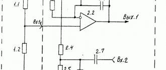
Let's take a closer look at this connection diagram, consisting of two pass-through switches . It requires two switches (also called “pass-through”), each of which has three contacts and two switching positions. Moreover, the switching mode must be “change-over”, that is, one contact is common to the other two. In one position it is closed with one of them, and in another position, naturally, with the other. Consequently, the general short circuit of all three contacts is completely eliminated.
Connection diagram for a pass-through switch for controlling a lamp from 2 places
Pass-through switch with three contacts and two positions (the common contact is on top)
Explanations for the diagrams
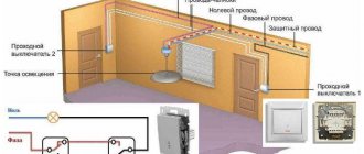
Now let's look at the drawn diagrams. Both circuits consist of a connection box, the pass-through switches themselves, a lamp and connecting wires (during installation, these will be two, three and four-core cables). The first diagram shows a connection diagram for a pass-through switch with control from two different places.
As you can see, one wire (in our case it is neutral) goes from the power source to the junction box and from there to the lamp. The other (phase wire), after the box, is connected to the common contact of one of the switches. Two switched contacts of one switch are connected to two contacts of the second switch (via a box). Well, from the common contact of the second switch, the phase is supplied to the second contact of the lamp.
As for the installation of this circuit itself: pass-through switches , from which three-core cables are output. Lamps are mounted that are connected in parallel and from which a two-core cable ultimately comes out.
Next, a connection box is installed in the most suitable location (taking into account the minimum cable length and the convenient location of this box). The cable from the lamps, power supply and the pass-through switches themselves is inserted into it. In this box the wires are connected to each other, as shown in the diagram.
Connection diagram for a pass-through switch for controlling a lamp from 3 places
How to control lighting from three places
The connection diagram for a pass-through switch with control from three places is not much different from the previous one (the general operating principle is the same). It adds another pass-through switch, which is slightly different from the previous ones. As can be seen from the diagram, this is a twin switch . That is, when one key is pressed, two contacts that are electrically independent of each other are simultaneously switched. In addition, as you should have noticed, there is a four-wire cable coming out of it.
Connection diagrams for pass-through switches of this type are good because they are relatively simple in their design (no additional components are required). But they are limited by the number of such control places.
The problem of independent lighting control from two places can also be solved using special pulse relays and units for remote lighting control.
Other ways to implement lighting control from two or more places:
Source: electric.info
How to connect a pass-through switch (light control from two or more points)
Current electricity prices make you think about saving where you never even thought about it before. For example, lighting on the stairs. It doesn’t matter if it’s in a private or multi-storey building, you still need to pay. Previously, they simply left the light on. Today you think about turning it off, but running up and down is also not fun. It turns out there is a solution. To prevent the lights from being on constantly, there are schemes for controlling the lamps from several places. That is, one or more lamps can be turned on and off from several points. Special switches are needed for this. They are called walk-throughs. Sometimes the names “duplicate” or “change-over” are found. All this is one type of electrical equipment. They differ from ordinary ones in a large number of contacts. Accordingly, the connection diagram for the pass-through switch is more complicated. However, you can figure it out.
conclusions
A pass-through switch is a modern electrical accessory that allows you to control lighting from 2 or more places. It allows you to turn lights on or off at the beginning and end of a room, at the top and bottom of a flight of stairs, or to control the lighting in an adjacent room.
The connection diagram for the pass-through switch makes it easy to install it yourself with minimal knowledge in electrical engineering and the presence of a certain tool.
Important! When installing a pass-through switch with your own hands, be sure to check the cable and wiring products for integrity using a conventional multimeter, since there are cases when the cable may be damaged, as a result of which, even with correct switching, the circuit will not work.
What does a pass-through switch look like and work?
If we talk about the front side, the only difference is: a barely noticeable arrow on the up and down key.
What does a single-key pass-through switch look like? You see there are double arrows
If we talk about the electrical circuit, everything is also simple: in ordinary switches there are only two contacts, in pass-through switches (also called changeover contacts) there are three contacts, two of which are common. There are always two or more such devices in the circuit, and they are switched using these common wires.
The difference is in the number of contacts
The operating principle is simple. By changing the position of the key, the input is connected to one of the outputs. That is, these devices have only two working positions:
- input connected to output 1;
- input is connected to output 2.
There are no other intermediate provisions. Thanks to this, everything works. Because the contact switches from one position to another, electricians believe it is more correct to call them “switches.” So a pass-through switch is also this device.
In order not to rely on the presence or absence of arrows on the keys, you need to inspect the contact part. Branded products should have a diagram on them that allows you to understand what type of equipment you have in your hands. It is definitely found on products from Lezard, Legrand, and Viko. They are often absent on Chinese copies.
This is what the changeover switch looks like from the rear
If there is no such diagram, look at the terminals (copper contacts in the holes): there should be three of them. But not always on inexpensive copies the terminal that stands alone is the input. They are often confused. To find where the common contact is located, you need to ring the contacts with each other at different key positions. This must be done, otherwise nothing will work, and the device itself may burn out.
You will need a tester or multimeter. If you have a multimeter, set it to sound mode - it beeps when there is contact. If you have a pointer tester, ring for a short circuit. Place the probe on one of the contacts, find which of the two it rings with (the device beeps or the arrow shows a short circuit - it deviates to the right all the way). Without changing the position of the probes, change the position of the key. If the short circuit is missing, one of these two is common. Now all that remains is to check which one. Without switching the key, move one of the probes to another contact. If there is a short circuit, then the contact from which the probe was not moved is the common one (this is the input).
It may become clearer if you watch a video on how to find the input (common contact) for a pass-through switch.
How to connect a hob is written here, and how to install and turn on a water heater is written in this article.
Recommendations
Instructions on how to make a switch yourself should be supplied in a kit with professional devices. This is another reason why it is necessary to choose only quality transfer switches.
Following these instructions, you can independently install switch boxes into the wall, leading wires from them to lamps and other similar devices.
- It is quite possible to make a pass-through switch from an ordinary one, but this requires skills and preferably specialized education, because you will have to resolder the circuit and add another contact.
- If a mistake is made in any place, the device may ignite during operation due to overvoltage or short circuit.
The number of pass-through switch points depends entirely on the goals and objectives set for the devices.
It is necessary to clarify exactly how many lighting elements will be connected to these devices, as well as determine the place from which the lighting will be controlled. The number of points can be 2 or more.
3 point circuit
To be able to turn the light on/off from three places, you need to buy a cross (cross) switch for two switches. It differs from those described earlier by the presence of two inputs and two outputs. It switches a couple of contacts at once. See the figure for how everything should be organized. If you understand the above, this one is easy to understand.
Electrical circuit for controlling a lamp from three points
How to assemble such a circuit? Here's the procedure:
- Zero (and ground, if any) is connected directly to the lamp.
- The phase is connected to the input of one of the pass-through switches (with three inputs).
- The input of the second is fed to the free wire of the lamp.
- The two outputs of one three-pin device are connected to the input of a crossover switch (with four inputs).
- The two outputs of the second three-pin device are connected to the second pair of switch contacts with four inputs.
The same diagram, but from a different perspective - where to connect the wires on the housings.
Where to connect the wires
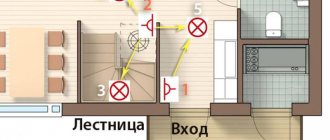
And this is approximately how to distribute it around the room.
Wiring when controlling the lamp from three places
If you need a circuit with four, five or more points, then it differs only in the number of cross switches (for four inputs/outputs). There are always two switches (with three inputs/outputs) in any circuit - at the very beginning and at the very end of the circuit. All other elements are cross devices.
Connection diagram for pass-through switches for 5 points
Remove one “crossbar” and you get a four-point control scheme. Add more and there will be a scheme for 6 control places.
To finally get it all in your head, watch this video.
Is it possible to control lighting from more than 2 places?
The answer to this question is of course yes. However, for these purposes, it is necessary to additionally include a crossover switch in the circuit. You can see the control diagram for lighting systems from three places in the following photo:
A single-line connection diagram using this method looks like this:
As you can see from the photo above, the main difference in lighting control between 2 and 3 place controls is the presence of a crossover switch and more connected wires in the junction box. Also, to connect a cross switch, it is necessary to use a cable with 4 cores or with 5 if there is a ground loop.
Two-key pass-through switch: connection diagram
To control the lighting of two lamps (or groups of lamps) from one switch from several places, there are two-key pass-through switches. They have six contacts. If necessary, find the common wires using the same principle as in a conventional device of this type, only you will have to connect a larger number of wires.
The connection diagram for a 2-key pass-through switch differs only in that there will be more wires: the phase must be supplied to both inputs of the first switch, just as from the two inputs of the second it must go to two lamps (or two groups of lamps, if we are talking about a multi-arm chandelier ).
The principle of connecting two-key pass-through switches
If you need to organize control of two light sources from three or more points, you will have to install two cross switches at each point: there are simply no two-key switches. In this case, one pair of contacts is placed on one crossbar, the second on the other. And then, if necessary, they are connected to each other. The outputs of both crossbars are connected to the last two-key transition switch in the chain.
How to organize control of two lamps from four places
If you think about it, everything is not so complicated, and the connection diagram for a pass-through switch from 2 points is generally simple. Just a lot of wires...
Source: stroychik.ru
Connection diagram of switches for controlling one light source from several places
To be able to control the lighting circuits, we need the following materials:
- distribution box with a diameter of 80 mm;
- 2 pieces of pass-through switches;
- flexible cable type PVSng or VVGng 3x1.5;
- 5 pcs of WAGO type terminal clamps for 2–3 contacts (or a soldering iron with tin and rosin);
- 2 pcs socket boxes for concrete (plasterboard).
The connection diagram for a pass-through switch made from the above materials will be as follows:
As we see in the above photo, to control lighting using pass-through switches, the neutral power wire in the terminal box is connected to the first output of lamps No. 1 and No. 2. The phase wire of the supply circuit in the distribution box is connected to terminal No. 1 of pass-through switch No. 1. The remaining two outputs of switch No. 1 are connected in the box to terminals No. 2 and No. 3 of switch No. 2, respectively. Next, pin No. 1 must be connected to the second free end of the lighting lamps.
The above circuit will allow you to fully control the lighting system, however, the above circuit does not protect a person from electric shock. For these purposes, the following connection diagram for the pass-through switch is used:
As we can see from the above photo, the main difference between the two schemes is the use of a three-core cable, which, in addition to phase and neutral, also contains a third grounding conductor. It allows, if the insulation in equipment or cable and wire products is damaged, to divert the resulting potential to the ground loop and cause the circuit breaker to trip.
Connecting a pass-through switch: how to do it correctly?
Pass-through switches allow you to control one lighting device from different points: for example, turn on the light at the entrance to the room, and turn it off while lying in bed. How to connect a pass-through switch? We explain in detail with diagrams and examples.
Pass-through switches are very convenient when you need to turn a light bulb on and off from different points in an apartment or house. For example, at the beginning of a corridor you can turn on a light bulb, and after passing through it, turn it off at the other end. Or on the first floor, light the lamp on the stairs, and when you get to the top, turn it off. How to properly install a pass-through switch so that everything works like a clock? We explain in detail with diagrams and examples.
What is required to connect a pass-through switch?
In order for the circuit to work, we need the following components:
- Two pass-through switches.
- Three-core wire type VVGng 3*1.5 mm 2 or NYM 3*1.5 mm 2
- Lamp.
- Phase + zero from the shield.
Pass-through single-key switches, unlike ordinary ones, have not two contacts, but three, so it will not be possible to use ordinary switches for such purposes. Conventional two-key switches also have three contacts, but they are also not suitable for pass-through installation, since they work differently.
Installation method
Wiring installation is a rather complex process; it is necessary to use only specialized objects and devices to connect wires.
- For example, a terminal box is perfect for a large number of changeover type devices.
- You can use the simple twisting method only if no more than 2 devices of this type are installed.
- However, even in this case, after twisting, the wires will need to be carefully soldered, and then wrapped with insulating tape for reliability.
- Next, they, as in any other cases, are placed in mounting boxes.
Connection diagram for pass-through switch
In order for the entire circuit to work properly, it is necessary to correctly connect the wires to the terminals inside the switch. In any pass-through single-key switch, the terminals are indicated by arrows: one will go inside the switch (phase) and two outside (output), as shown in the figure below. If you mix up and connect the phase wire to the arrow that goes out, the circuit will not work correctly.
The connection diagram for the pass-through switch is as follows: zero from the meter is supplied through the distribution box directly to the light bulb. The phase from the meter is supplied to switch 1; two outputs of switch 1 are connected to the outputs of switch 2; phase from switch 2 goes to the light bulb. Pay attention to diagram 1: here the contacts on the switch are open, so the light bulb is off.
Suppose a person passing through the corridor turns on switch 1, thereby closing the circuit and turning on the light bulb. In this case, the diagram becomes like this:
At the end of the corridor he presses switch 2, the circuit opens and the light bulb turns off (diagram 3). In this case, in order to turn on the light bulb again, he does not need to return to switch 1 - just press the button of switch 2.
With this scheme, the light bulb can be controlled by any switch, without even using the second one. Now let's see how to connect the switch directly to the junction box.
Connecting a pass-through switch in a distribution box
In the distribution box we see 10 wires: 2 come from the switchboard, 2 from the light bulb and 3 from each switch. We connect the wires as follows: we connect the blue zero ( 1 ) from the panel board directly to the blue zero ( 1 ) of the light bulb. the phase from the switchboard ( 2 ) to the white wire ( 2 ) of the first switch. Then the red output ( 3 ) of the first switch with the red output ( 3 ) of the second. We also connect the green wires ( 4 ). the white wire ( 5 ) of the second switch to the phase wire ( 5 ) of the light bulb. We wrote here how to properly connect wires.
In some apartments there is also a yellow-green ground wire coming from the switchboard. It does not fit into the pass-through switches, but is placed on a separate terminal. Once everything is connected, apply power from the electrical room and check the operation of each switch. If anyone can turn the lamp on and off, then the circuit is connected correctly.
Pass-through switch connection diagram
Conventional switches that are installed in our homes are capable of turning lights on and off from one place. Agree that the chandelier, which is located in the bedroom, can only be turned on with the switch, which is located there.
But what to do if you need to control one lamp from different rooms at the same time. It is difficult to assemble such a circuit using conventional switches. Pass-through switches, or switches as they are also called, will come to the rescue.
Such switches are used to organize control of lamps independently from several places. The proposed connection scheme is not only very convenient, but also allows for quite significant energy savings.
In this article, let's look at how to assemble a circuit diagram for connecting a pass-through switch in a distribution box.
The use of walk-through switches to control the lighting of staircases is especially important. Often, circuits using time relays are used for this purpose, but it should be recognized that they are not so convenient to use, less reliable and economical.
Everyone moves up stairs at different speeds, and you yourself can climb light today, and tomorrow with a heavy suitcase. Setting large time delays taking into account the reserve means reducing savings.
The proposed scheme allows you to turn on the lamps below with one switch, and when going up the stairs, turn them off with another. If you need to go downstairs, you use the walk-through switch at the top to turn on the light and at the bottom to turn it off. It is also convenient to use a similar scheme for lighting long corridors.
However, pass-through switches will be useful not only for owners of long corridors and multi-story buildings. They will also be very useful for residents of small apartments. Typical situation. Your apartment has a walk-through room, when entering which you turn on the light, then go to the next room, turn on the light in it, and turn off the lighting in the walk-through room that has become unnecessary. Agree - very convenient. Eliminates unnecessary walking and saves electricity.
One more example. You go into the bedroom and turn on the light at the door. When you go to bed, you turn on the table lamp or sconce to read a book before bed, but now you have to get up again, go to the door and turn off the chandelier! But you don’t have to do this if you have previously installed a pass-through switch at the head of the bed.
To implement such a control scheme, so-called “pass-through switches” are used, which, strictly speaking, are actually switches. Unlike conventional switches, they have not two, but three contacts and can switch the “phase” from the first contact to the second or third.
Any type of lamp can be used as a light source in such a scheme - from conventional incandescent lamps to fluorescent, energy-saving and LED. However, using the same scheme, you can connect not only lamps, but also any other load, the activation of which you need to control from several places.
Application area of pass-through switches
Installation and connection of a pass-through switch will be useful when controlling lighting systems in the following cases:
- in the presence of large corridors or walk-through rooms;
- when controlling lighting fixtures at the entrance to the room and directly near the bed;
- when installing lighting in large industrial and industrial buildings;
- if necessary, control the lighting in the next room;
- in the presence of stairs connecting several floors (in most cases in cottage premises) and so on.
Let us consider in more detail what the requirements for the installation of electrical accessories are, the basic installation rules and what is the wiring diagram for the pass-through switch.
How to connect a pass-through switch - control circuit for a lamp from 2 places
The procedure for connecting a pass-through switch is not much different from connecting a conventional switch. The only difference is in the number of contact terminals and wires supplied. The pass-through switch has three of them.
Please note in advance that you need to stretch a three-core wire from the junction box to such a switch.
Pass-through switch connection diagram - control of a lamp from 2 places
The circuit uses two pass-through switches and a distribution box into which wires from the controlled lamp and three-wire wires from the switches are inserted.
The phase wire from the junction box is connected to the common input contact of the first pass-through switch. The other two (output) contacts are connected to wires coming from similar contacts of the second switch. And the common (input) contact of the second switch is connected to the wire coming from the lamp.
The second wire from the lamp is directly connected to the junction box zero.
The cross-section of the three-core wire supplied to the pass-through switches must be selected in accordance with the power of the controlled luminaire.
How to connect a pass-through switch - control circuit for a luminaire from 3 places
In certain cases, it becomes necessary to provide not two, but more control points for lamps. For example, the light on the stairs of a multi-story building must be turned on and off on each floor. The same situation occurs with a long corridor into which the doors of several rooms open.
It is possible to implement such a scheme, but in addition to simple pass-through switches, you will also need cross switches. Such switches no longer have three, but four contacts - two input and two output, representing two pairs of simultaneously switched contacts. Accordingly, a four-wire wire must be connected to such switches.
Pass-through switch connection diagram - control of a lamp from 3 places
In this control scheme, conventional pass-through switches are used at the first and last control points of the lamps and cross switches at all the others.
The number of control points is not limited; only the complexity of switching in the distribution box increases due to the large number of wires connected to it. And here you cannot do without proper marking of the wires when laying them, otherwise you will simply get confused in them.
The connection principle is as follows: the output pair of contacts of the first pass-through switch is connected to the wires going to the input pair of the next cross switch, and so on, up to the last pass-through switch, the common contact of which is connected to the wire going to the lamp. The phase wire is connected to the input contact of the first switch, and the second wire from the lamp is connected to the zero of the junction box.
We stretch a three-wire wire to each pass-through switch, and a four-wire wire to each crossover switch.
The diagram presented shows the connection of three lighting control points, consisting of one crossover and two pass-through switches.
A little clarification on the connection diagrams
Let's look at how the pass-through switch connection diagram . The presented diagrams use the following elements: connection box, lamp, pass-through switches and connecting wires, for which, during the installation process, cables of different designs are used.
The first of the proposed circuits represents the connection of a pass-through switch, in which control is carried out from two different locations; this type of circuit is considered quite simple to implement.
With this type of connection, one wire, which is neutral, is directed from the source of electricity to the lamp through the junction box. The second, which is phase, is also directed through the junction box to the switch contact.
Thus, two pairs of switch contacts are connected to each other. To light the lamp, the phase is supplied to the lamp from the common contact of the second pass-through switch.
The second diagram shows the connection of pass-through switches together with a changeover or cross switch. This scheme makes it possible to control lighting from three different places.
We’ve figured out the connection diagram, now let’s learn more about its installation. It consists of installing pass-through switches and further laying three-core cables from them. Lamps connected in parallel are also installed, from which a two-core cable extends.
At the same time, we also install a junction box, where we lay cables from: switches, lamps, and power supply, to connect them together, in accordance with the above diagram. In this case, you should pay attention to choosing a suitable location for installing the junction box, taking into account the length of the cables used.
I hope this article “ pass-through switch connection diagram ” helped you deal with all the connection issues, if you have any questions or suggestions, ask them in the comments, I will be happy to answer.
Light control from 3 or more places
In a circuit designed for three (and not two, as in the previous case) points, 2 switches are used (they are called changeover in this case) and one new element: a cross switch, which makes two switches at a time, that is, moves two jumpers at once (two contacts change their position).
The assembly diagram, starting from the third point, becomes a little more complicated:
- The neutral wire goes to the light bulb.
- The ground wire goes to the light bulb.
- The input of the second switch is to the free wire of the light source (to the lamp).
- Phase wire - to the input of the pass-through switch (with three inputs).
- Both outputs of the first three-pin switch go to the input of the cross switch (with four inputs).
- Both outputs of the second three-pin switch are branched (each into two more) and go to the second pair of switch contacts with four inputs (four cores).
If you need to control the on and off of a light bulb from four, five or more places, the circuit described for three points changes slightly - more cross switches are added. When there are n points for controlling the light, then you need to purchase such switches in the amount of (n-2) pieces. And they will always be located in the middle in the circuit, where there is a current source at one end and a light source (lamp) at the other.
When, for convenience and saving electrical energy, there is a need to control the light of two light bulbs (two groups of lamps) from three or more places, the circuit described in the previous paragraph, but more complicated, is used. Each of the key switches (each point), except the first and last, is equipped with two cross current switches. At the beginning of the circuit, one bifurcated contact (pair of contacts) according to the diagram goes to the first, so-called crossbar, and the second, respectively, to the second crossbar.
Next in the circuit there is a series of cross switches. Their number depends on the number of light control places. In the final section of the electrical circuit there is a single switch, the same as the first one. Since you can connect not four, but two wires to it, you need to connect these four wires in pairs, making two of them. All connections are made using terminals with the voltage turned off.
Switching boxes that collect connected wires in one place and protect them from external influences, in this case you need to take larger ones (diameters from one hundred millimeters) or in larger quantities (several standard boxes with a diameter of 60 mm).
Installing the wiring and switches is not difficult if you follow the above rules. After laying the wiring, you can put plasterboard on top (ceiling or wall - depending on the location of the wires) and only after that you can glue the wires. When laying wiring on the wall, it is usually placed fifteen centimeters from the ceiling.
What is the difference between a pass-through switch and a regular switch?
If you look at the pass-through switch from the side, you will not find any external differences. The significant and only difference between such switches and simple ones lies within their design.
A conventional single-pole single-key switch has two contacts in its design, fixed and movable. The moving contact is driven by a key that we press by hand and closes with the fixed contact. This closes the electrical circuit and supplies power to the lamp. There are also designs of two-pole single-key switches that essentially perform the same function as the previous one. Its difference is that the neutral wire going to the lamp breaks in the same way as the phase wire. This was done to improve security.
Figure 1. Schematic diagram for connecting single-pole and double-pole single-key switches
The pass-through switch has two fixed and one moving contacts. The moving contact is always closed with one of the fixed ones. When you press a key and move it from one position, for example, "off" to another position - "on", the moving contact also changes its position, opening with a closed contact and closing with an open one. That is, the pass-through switch does not have an “off” position and it works not as a switch, but as a switch. Therefore, in technical literature and in manufacturers’ catalogs it is correctly called a switch. For example: “single-pole, single-gang, double-throw switch.” Keep this in mind when you buy switches to assemble a control circuit from two places.
In addition to single-pole switches, there are double-pole and even three-pole switches. For ease of understanding, in this article we will use the expression not a switch, but a pass-through switch, since it is more often used among people.
Where is a similar lighting control system used?
The lighting control system most often considered is used in public and industrial premises, namely: in long corridors, tunnels, walk-through rooms, that is, in rooms where there are two doors equally serving as entrance and exit, in staircases and other places. In all of the above cases, pass-through switches are installed next to the doors.
If we talk about residential premises, then the installation location for pass-through switches can be, for example, the entrance door to the room and a place on the wall next to the bedside table. In this case, a person entering the room will turn on the light by pressing the pass-through switch located next to the door, and sitting on the bed, without getting up, he can turn it off with the second pass-through switch located next to the bed.
Using pass-through switches, you can control one luminaire or lamp, or a group of them. For each case, different types of pass-through switches are used (single-key, two-key, three-key). The main goal that a person pursues when installing such switches is the convenience of light control and reducing energy costs.
Where and why are pass-through switches installed?
Sometimes when controlling lighting you need to turn lights on or off from two or more places. This situation can arise in rooms without constant presence of people - long passages or large areas with two or more exits. When entering the corridor you need to turn on the light, when leaving - turn it off. For this purpose, pass-through switches have been developed and produced - such a circuit can be easily built on them. Another example is lighting of staircases (flights). Upon entering the house, you need to turn on the light, and when you go up to the desired floor, turn it off. Therefore, such devices are also called marching (and also backup or reversible).
In residential premises, such devices can be used in large rooms with several entrances, as well as in bedrooms. When entering the bedroom, you can turn on the light and turn it off with the device next to the bed. The lighting of children's rooms for one or several children is built using the same principle - one switch at the entrance, the rest - near each child's sleeping place.
It is very convenient to turn off the lights without getting out of bed.
Advantages and disadvantages
The advantages of a walk-through device appear when it is used in the area intended for it. With its help, you can create lighting control circuits that cannot be built with conventional devices. The only disadvantages include the inability to determine the state of the lamps by the position of the key. And this minus cannot be circumvented .
Connecting a pass-through single-key switch
Figure 2 shows a schematic diagram of connecting pass-through switches designed to control one lamp or one group of lamps from two places remote from each other. As you probably already understood, a single-pole pass-through switch has two fixed contacts and one changeover contact. The changeover contact of one of the switches is supplied with supply voltage. The changeover contact of the second switch is connected to the lamp, and the lamp, in turn, is connected to the neutral wire of the supply network. The fixed contacts of the first switch will be connected by two separate conductors to the two fixed contacts of the second switch.
Figure 2. Schematic diagram for connecting a pass-through switch with one pole and one key
In the diagram, the position of the changeover contacts of both switches is the same, which corresponds, for example, to the lowered position of their keys. The electrical circuit is open. If we press the key of the first switch and move it to the raised position, then the changeover contact of this switch will accordingly also change its position and close the electrical circuit. An electric current will flow through the circuit (the direction of the current is shown by arrows), and the lamp will begin to glow. If you now press the key of the second switch and also change its position, the circuit will again be open and the lamp will go out.
For a more visual representation of how the conductors are connected, Figure 3 shows a wiring diagram for connecting pass-through switches. The green circle is nothing more than a distribution box, inside which the wires are connected. The round pieces inside the box are soldered wires, made in the form of twists with welding, crimped with self-clamping insulating caps, connected with terminals or a screw connection. Everything else I think is clear.
Figure 3. Wiring diagram for connecting single-pole single-key pass-through switches
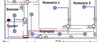
Figure 4 below shows a diagram of the arrangement of equipment and routing of wires. The connection of the wires in this case is made in two distribution boxes 1 installed above the pass-through switches 3. This was done in order to save wires. If we installed one junction box and assembled the circuit in it, we would have to lay two more wires from the box to the switch closest to us. If the supply wires were supplied from the side of lamp 2, then all connections could be made in one box without unnecessary wiring costs.
Here: L – linear (phase) wire; N – neutral wire; PE – ground wire.
Figure 4. An example of a lighting control circuit from two places using pass-through single-pole single-key switches
Connecting a pass-through two-key switch
The electrical circuit of a two-pole two-key pass-through switch is similar to the electrical circuit of a single-pole single-key pass-through switch. The difference is that another set of contacts is built into one housing (another movable and two fixed contacts). Externally, a pass-through two-key switch is similar to a regular double switch.
The purpose of two-key pass-through switches is to divide one large group of lamps or luminaires into two groups. That is, their operation is similar to the operation of a conventional double switch installed in the living room and designed to turn on the lamps of a large beautiful chandelier.
The two-key pass-through switch is connected in accordance with the circuit diagram shown in Figure 5. The directions of the currents are indicated by arrows.
Figure 5. Schematic diagram of connecting a pass-through two-key switch
Figure 6. Wiring diagram for connecting two-pole two-key pass-through switches