Color pinout of computer power supply connectors
Modern computers use ATX power supplies, and a 20 or 24 pin connector is used to supply voltage to the motherboard. The 20-pin power connector was used during the transition from the AT standard to the ATX. With the advent of the PCI-Express bus on motherboards, 24-pin connectors began to be installed on power supplies.
The 20-pin connector differs from the 24-pin connector in the absence of contacts numbered 11, 12, 23 and 24. These contacts in the 24-pin connector are supplied with the duplicated voltage already present on the other contacts.
Pin 20 (white wire) previously served to supply −5 V in power supplies for ATX computers versions prior to 1.2. Currently, this voltage is not required for the operation of the motherboard, so in modern power supplies it is not generated and pin 20 is usually free.
Sometimes power supplies are equipped with a universal connector for connecting to the motherboard. The connector consists of two. One is twenty-pin, and the second is four-pin (with pin numbers 11, 12, 23 and 24), which can be attached to a twenty-pin connector and it will become 24-pin.
So if you are replacing a motherboard that requires a 24-pin connector instead of a 20-pin connector, you should pay attention; it’s quite possible that an old power supply will work if its set of connectors has a universal 20+4-pin connector.
In modern ATX power supplies, there are also auxiliary 4, 6 and 8 pin connectors to supply +12 V voltage. They serve to supply additional supply voltage to the processor and video card.
As you can see in the photo, the +12 V supply conductor is yellow with a black stripe.
A Serial ATA connector is currently used to power hard drives and SSDs. Voltages and contact numbers are shown in the photo.
Outdated power supply connectors
This 4-pin connector was previously installed in the power supply to power a floppy drive designed for reading and writing from 3.5-inch floppy disks. Currently found only in older computer models.
Floppy disk drives are not installed in modern computers, as they are obsolete.
The four-pin connector in the photo is the one that has been in use for the longest time, but is already obsolete. It served to supply +5 and +12 V supply voltage to removable devices, hard drives, and disk drives. Currently, a Serial ATA connector is installed in the power supply instead.
The system units of the first personal computers were equipped with AT-type power supplies. One connector consisting of two halves was suitable for the motherboard. It had to be inserted in such a way that the black wires were next to each other. The supply voltage to these power supplies was supplied through a switch that was installed on the front panel of the system unit. However, according to the PG pin, it was possible to turn the Power Supply on and off using a signal from the motherboard.
Currently, AT power supplies are almost out of use, but they can be successfully used to power any other devices, for example, to power a laptop from the mains if its standard power supply fails, to power a 12 V soldering iron, or low-voltage light bulbs , LED strips and much more. The main thing is not to forget that the AT power supply, like any switching power supply, is not allowed to be connected to the network without an external load.
What does “power supply” mean in a computer and where is it located?
The vacuum cleaner did not help, rebooting, replacing the battery and resetting CMOS and it was time to test the power supply. Like any household device, the computer is powered from a 220 volt outlet. But its filling works with much lower voltages - from 12 volts and below.
To reduce the voltage to the required values and ensure reliable and safe operation, power supplies are installed in computers. These are smart devices equipped with various protection circuits - short circuit, power surges, incorrect connection. If there are malfunctions on the motherboard regarding power supply, the unit may not turn on and will go into protection.
But most often the unit itself has to be replaced due to failure of its internal elements. It all depends on the quality of the parts and in what conditions the equipment is operated. Over time, parts lose their performance characteristics and, although it starts, it no longer produces factory characteristics. And all we get is a dark monitor and spinning fans.
In IBM-compatible computers, the power supply can be easily replaced with a new one. They are removable, compatible and easy to change. On monobok devices, or from Apple, you need to look for blocks for a specific model.
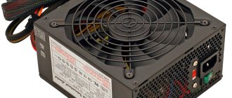
So, the power supply on a regular home system unit can be seen on its rear panel. It is secured with four or five bolts for a Phillips screwdriver. Full size looks about the same everywhere:
Reference table of color markings, voltage values and ripple range on power supply connectors
Wires of the same color coming out of the computer's power supply are soldered internally to one track of the printed circuit board, that is, connected in parallel. Therefore, the voltage on all wires of the same color is the same value.
| Table of color marking of wires, output voltages and ripple range of ATX power supply | |||||||
| Output voltage, V | +3,3 | +5,0 | +12,0 | -12,0 | +5.0 SB | +5.0 PG | GND |
| Wire color coding | orange | red | yellow | blue | violet | grey | black |
| Permissible deviation, % | ±5 | ±5 | ±5 | ±10 | ±5 | – | – |
| Permissible minimum voltage | +3,14 | +4,75 | +11,40 | -10,80 | +4,75 | +3,00 | – |
| Permissible maximum voltage | +3,46 | +5,25 | +12,60 | -13,20 | +5,25 | +6,00 | – |
| Ripple range no more than, mV | 50 | 50 | 120 | 120 | 120 | 120 | – |
Voltage +5 V SB (Stand-by) – (purple wire) is generated by an independent low-power power supply built into the power supply unit, based on one field-effect transistor and a transformer. This voltage ensures the computer operates in standby mode and serves only to start the power supply. When the computer is running, the presence or absence of +5 V SB voltage does not matter. Thanks to +5 V SB, the computer can be started by pressing the “Start” button on the system unit or remotely, for example, from an uninterruptible power supply unit in the event of a prolonged absence of 220 V supply voltage.
Voltage +5 V PG (Power Good) - appears on the gray wire of the power supply unit after 0.1-0.5 seconds if it is in good condition after self-testing and serves as an enabling signal for the operation of the motherboard.
When measuring voltages, the “negative” end of the probe is connected to the black wire (common), and the “positive” end is connected to the contacts in the connector. You can measure output voltages directly while the computer is running.
A voltage of minus 12 V (blue wire) is only needed to power the RS-232 interface, which is not installed in modern computers. Therefore, in power supplies of the latest models this voltage may not be present.
The deviation of the supply voltages from the nominal values should not exceed the values given in the table.
When measuring the voltage on the wires of the power supply, it must be connected to a load, for example, to a motherboard or a homemade load block.
5 volts is one of the most widely used voltages. Most programmable and non-programmable microcontrollers, all kinds of indicators and testers are powered from this voltage. In addition, 5 volts is used to charge all kinds of gadgets: phones, tablets, players, and so on. I'm sure every radio amateur can come up with many uses for this voltage. And in this regard, I have prepared for you three good, in my opinion, options for power supplies with a stabilized output voltage of 5 volts.
The first option is the simplest.
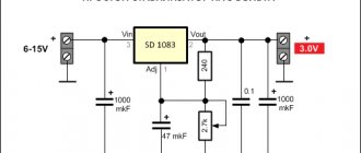
This option is distinguished by a minimal number of parts used, extreme ease of assembly and incredible 'survivability' - the block is almost impossible to kill. So let's move on to the diagram.
This circuit is copied from an inexpensive phone charger, has stabilization of the output voltage and is capable of delivering a current of up to 0.5 A. In fact, the unit can output more, but as the current at the output increases, the overload protection begins to operate and the output voltage begins to decrease. Protection against overloads and short circuits is implemented using a 10 ohm resistor in the emitter circuit of the power transistor and a low-power transistor s9014 . When the current through the primary winding of the transformer increases, a voltage drop is created on the emitter resistor sufficient to open s9014, which in turn pulls the base of the power transistor to negative, thereby closing it and reducing the duration of the pulses through the primary winding. By changing the value of this resistor, you can increase or decrease the protection operation current. You should not increase it too much, as this will entail an increase in heating of the power transistor and increase the likelihood of the latter failing.
Stabilization is performed using the common optocoupler pc817 and a 3.9 V zener diode (by changing the value of which you can change the output voltage). When the output voltage is exceeded, the optocoupler LED begins to glow brighter, causing an increase in the current through the optocoupler transistor to the s9014 base and, as a result, closing the power switch. When the output voltage decreases, on the contrary, the optocoupler transistor will begin to close and s9014 will not interrupt the pulses based on the power switch, thereby increasing their duration and, accordingly, increasing the output voltage.
Particular attention should be paid to winding the transformer. This is often a factor that pushes beginners away from switching power supplies. So, since the block is single-ended, we will need a transformer with a non-magnetic gap between the core halves. The gap is needed to quickly demagnetize the core and to prevent the ferrite from entering saturation. The calculation of the transformer should ideally be carried out in special programs, but for those who do not want to do this, I will say that in such low-power power supplies the primary winding consists of 190-220 turns of 0.08-0.1mm wire. Roughly speaking, the larger the core, the fewer turns. The base winding is wound on top of the primary in the same direction. It consists of 7 - 15 turns of the same wire. And at the end the secondary is wound with a thicker wire. The number of turns is 5-7. It is extremely important to wind all the windings in the same direction and remember where the beginning and end are. On the diagram and on the board (which you can download here), the dots indicate the beginning of the windings.
There is nothing more to add regarding the scheme; it is quite simple and does not require any special skills for assembly. All components can be changed within 25%, the unit will work perfectly. The power transistor can be installed with any reverse conductivity corresponding to the power and with a calculated collector voltage of at least 400 volts. The base transistor is any low-power NPN with the same pinout as s9014 .
This unit can be powerfully used where high current is not needed, but compactness is needed, for example, for powering Arduino or for charging devices with small-capacity batteries. The advantages of this power supply include its compactness, the presence of protection and stabilization, and, of course, ease of assembly. The only downside is, perhaps, the low output power, which, by the way, can be increased by increasing the capacity of the input filter capacitor.
By the way, the block looks like this:
The second option is more powerful.
This option is very similar to the previous one, but more powerful. The block has improved feedback and, therefore, better stabilization. Let's take a look at the diagram.
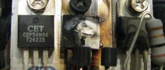
The circuit is a standby power supply unit for a computer power supply. Unlike the previous circuit, this one has a more powerful power transistor, a larger input filter capacitor and, most importantly, a transformer with a larger overall power. All this just affects the output power. Also in this circuit, unlike the first, normal stabilization is done on the TL431 - the reference voltage source.
The principle of operation here is the same as the previous option. An initial bias voltage is applied through a 560 kOhm resistor to the base of the power switch, it opens slightly and current begins to flow through the primary winding. An increase in current in the primary causes an increase in current in all other windings, which means that the current arising in the base winding will open the transistor even more, and this process will continue until the transistor is completely open. When it opens, the current through the primary will stop changing, which means the secondary will stop flowing and the transistor will close and the cycle will repeat.
I spoke in detail about the operation of current protection and stabilization above and see no point in repeating myself, since everything works exactly the same here.
Since this power supply is made on the basis of a computer unit, I used a ready-made transformer and did not rewind it. Transformer EEL-19B. Estimated overall power 15 – 20 W.
As in the previous circuit, the component values can be deviated within 25%, since in different computer power supplies this circuit works perfectly with different components. This instance, thanks to the output current of 2 A, can be used as a charger for phones and tablets or for other consumers requiring high current. One of the advantages of this design is the ease of obtaining radio components, because everyone probably has a non-working power supply from an old computer or TV, and there the elementary base is enough for 3 - 4 such power supplies. Also a plus can be considered a considerable output current and good stabilization. Of the minuses, we can rightly note the size of the board (it is quite high due to the transformer) and the possibility of whistling during idle. The whistle may appear due to a malfunction of some element, or simply due to the conversion frequency being too low at idle. Under load the frequency increases.
The block looks like this:
The third option is the most powerful.
This option is for those who need enormous power and excellent stabilization. If you don't mind sacrificing compactness, this unit is especially for you. So, let's look at the diagram.
Unlike the previous two options, this one uses a specialized PWM controller UC3843 , which, unlike transistors, can change the pulse width and is specially made for use in single-ended power supplies. Also, with UC, the frequency does not change depending on the load and it can be clearly calculated in specialized calculators.
So the principle of operation. The initial power is supplied through a 300 kOhm resistor to the 7th leg of the microcircuit, it starts up and begins to generate pulses that come out from the 6th leg and go to the field device. The frequency of these same pulses depends on the elements Rt and Ct. With the specified components, the output frequency is 78.876 kHz. By the way, here is the device of the microcircuit:
This microcircuit is very convenient to implement current protection; it has a special output for this – current sense. If the voltage is more than 1 volt, the protection will work on this leg and the controller will reduce the duration of the pulses. Stabilization here is done using the built-in error amplifier current sense comparator. Since we have 0 volts at pin 2, the amplifier is error amp. It always produces a logical one and it goes to the input of the current sense comparator amplifier, thereby forming a reference voltage of 1 volt at its inverting input. When the voltage at the output of the power supply exceeds, the phototransistor of the optocoupler opens and shunts 1 pin of the microcircuit to minus. In this case, the voltage at the inverting input of the current sense comparator decreases, and since the voltage at its non-inverting transistor at the moment of opening increases, at some point it will exceed the voltage at the inverting input (the same thing happens during a short circuit) and the current sense comparator will produce a logical unit, which in turn will lead to a decrease in the pulse duration and, ultimately, to a decrease in the voltage at the output of the power supply. The stabilization in this power supply is very good, so that you understand how good it is, when you connect a 1 Ohm resistor to the output, the voltage drops by only 0.06 volts, while 25 W of heat is dissipated on it and it burns out in a couple of seconds. In general, this unit can output both 30 W and 35 W, since a field-effect transistor is used here as a key. The diagram shows 4n60, but I used irf840 since I have a lot of them. The microcircuit can supply a current of up to 1 A to control the field switch, which makes it possible to control fairly powerful field switches without an additional driver.
The transformer for this unit was taken from a burnt-out 100-watt energy-saving lamp. The primary consists of 120 turns of 0.3 mm wire, the self-powering winding is 20 turns of the same wire, and the power output winding is 5 turns of two 1 mm wires. At the output there is a full-fledged interference filter, which allows you to use this power supply where interference is not needed.
PSUs can be used in very powerful chargers for gadgets. It can easily charge 6 or even 7 devices simultaneously, while providing a stable 5 V output.
It all looks something like this:
Here are their relative sizes:
Printed circuit boards
Well, that's all. If there are any points that interest you that I have not mentioned, please email them to me. The email address is being protected from spambots. Javascript must be enabled in your browser to view the address.
Dmitry4202
Installing an additional video card connector in the computer's power supply
Sometimes there are seemingly hopeless situations. For example, you bought a modern video card and decided to install it in your computer. There is the necessary slot on the motherboard for installing a video card, but there is no suitable connector on the wires for additional power supply to the video card coming from the power supply. You can buy an adapter, replace the entire power supply, or you can independently install an additional connector on the power supply to power the video card. This is a simple task, the main thing is to have a suitable connector, it can be taken from a faulty power supply.
First you need to prepare the wires coming from the connectors for the offset connection, as shown in the photo. An additional connector for powering the video card can be connected to the wires going, for example, from the power supply to drive A. You can also connect to any other wires of the desired color, but in such a way that there is enough length to connect the video card, and preferably nothing to them was no longer connected. The black wires (common) of the additional connector for powering the video card are connected to the black wire, and the yellow wires (+12 V), respectively, to the yellow wire.
The wires coming from the additional connector for powering the video card are tightly wrapped with at least three turns around the wire to which they are connected. If possible, it is better to solder the connections with a soldering iron. But even without soldering, in this case the contact will be quite reliable.
The work of installing an additional connector for powering the video card is completed by isolating the connection point, several turns, and you can connect the video card to the power supply. Due to the fact that the twisting points are located at a distance from each other, there is no need to isolate each twist separately. It is enough to cover only the area where the wires are exposed with insulation.
How to quickly check the computer's power supply for functionality and replace it?
Now that we have decided, it’s time to check our power supply. We disconnect the system unit from the network and place it on the table. First you need to open the case by unscrewing the bolts in the back. Look at the video, I filmed the replacement process on my action camera:
If possible, we use a used unit for diagnostics, even if it is old, even of less power, but obviously working. We will temporarily connect it instead of the faulty one. The main thing for us is to make sure whether the computer will start with this block or not. And you don't need any complicated measurements.
We carry out all operations with the system unit completely disconnected from electricity; the power cables must be disconnected!
After opening, we sequentially disconnect the connectors of the “native” unit from the motherboard and immediately connect the connectors from the test unit in their place. We are not removing the old block yet! First the largest 24 pin connector. Press the latch and pull it out:
The following connector is near the processor:
Disconnect power from the hard drives and CD DVD drive...
If the power supply is connected to the video card from the power supply, we also disconnect it. If the board has ATX 12 volt power connectors
By the way, due to a faulty video card, the power supply goes into protection. You can try to remove the video card from the slot and if the computer starts, congratulations, you have found that the video card is faulty, and so far everything is in order with the power supply.
We connect all the connectors of the test block to their places and check the quality of the connection. Everything should click, in the right places and to the end. Connect the monitor. After that, connect the power from the outlet (don’t forget about the switch on the back wall).
Turn on the power. If the system starts, you will hear a joyful squeak, and the boot script will appear on the display. Hooray! Turn it off and you can check it again. Then you need to remove the “original” unit by unscrewing the bolts on the rear panel of the system unit.
If there are ties, carefully cut them with scissors so as not to damage the wires and elements on the motherboard. Let's not rush! If necessary, remove another cover of the system unit.
If possible, we take the faulty power supply with us to the store and choose the same power supply, size and number of connectors. We install everything in reverse order. There is no need to throw it away; you can send it for repairs - it will still serve, and not only in the computer.
Refinement of the power supply connector for connecting the motherboard
When the motherboard fails or a computer is modernized (upgraded) and involves replacing the motherboard, I have repeatedly had to deal with the lack of a 24-pin power supply connector on the power supply.
The existing 20-pin connector fit well into the motherboard, but the computer could not work with this connection. A special adapter or replacement of the power supply was required, which was an expensive pleasure.
But you can save money if you do a little work yourself. The power supply, as a rule, has many unused connectors, among them there may be four, six or eight pins. The four-pin connector, as in the photo above, fits perfectly into the mating connector on the motherboard, which was left unoccupied when installing the 20-pin connector.
Please note that both in the connector coming from the computer's power supply and in the mating part on the motherboard, each contact has its own key, which prevents incorrect connection. Some contact insulators have a shape with right angles, while others have cut corners. You need to orient the connector so that it fits. If you can’t find the position, then cut off the interfering corner.
Separately, both the 20-pin and 4-pin connectors fit well, but they don’t fit together and interfere with each other. But if you grind down the contacting sides of both connectors a little with a file or sandpaper, they will fit in well.
After adjusting the connector housings, you can begin connecting the wires of the 4-pin connector to the wires of the 20-pin connector. The colors of the wires of the additional 4-pin connector are different from the standard one, so you do not need to pay attention to them and connect them as shown in the photo.
Be extremely careful, mistakes are unacceptable, the motherboard will burn out! Near left, pin No. 23, black in the photo, connects to the red wire (+5 V). Near right No. 24, yellow in the photo, is connected to the black wire (GND). The far left, pin No. 11, black in the photo, connects to the yellow wire (+12 V). The far right, pin No. 12, yellow in the photo, is connected to the orange wire (+3.3 V).
All that remains is to cover the connection points with a few turns of insulating tape and the new connector will be ready for use.
In order not to think about how to correctly install the assembly connector into the motherboard connector, you should apply a mark using a marker.
What you need to know when choosing a power supply for your PC
The power supply is one of the most important elements of a computer, although it does not directly affect its performance. When choosing a power supply, you need to choose a device that can meet the requirements of your particular PC build. In this publication, we will analyze the main characteristics that you should pay attention to when choosing a power supply for the correct operation of your PC. Please note that below you will find basic information that will help guide you in your search and determine which nuances you may need to deepen your knowledge.
Content
- We select the power supply by power
- Energy efficiency and efficiency
- Form factor and connection types
- What is PFC
- Putting knowledge into practice
We select the power supply by power
No matter how simple it may sound, in order to determine the power of the future power supply, you need to add up the power consumption of all PC components and make a small reserve in case of any changes or upgrades. You should also take into account one point, which is that power supplies from unknown brands often overestimate their characteristics, or the indicated power of the power supply is calculated at maximum load. Thus, if the PSU operates at peak power continuously, it will undoubtedly reduce its lifespan and may lead to various power failures. If, when choosing, you still give preference to a little-known brand, you should buy a power supply with a power reserve of at least one and a half times, and preferably twice. I will add that the power of the power supply should be selected from the nominal consumption values of all PC components, and not the peak values. To cover peak power consumption, we take a power supply with a power reserve.
As for real numbers, it should be said that a power supply with a power of up to 400 W is sufficient for an office PC or a computer for household tasks. As for modern PCs for gaming, you often have to use a power supply with a power of 800-900 W or more. When choosing a power supply, I also recommend not to forget about the energy consumption of cooling systems and all kinds of decorative lighting. For your convenience, you can find a special calculator for calculation on the Internet.
Energy efficiency and efficiency
Efficiency determines the ratio of the power consumption of the power supply to its actual output power. To facilitate the task of choosing the “right” power supply for you, there is a special Energy Star standardization. If I'm not mistaken, the latest version of this standard is 4.0, but as far as I know, there were updates to this version of the standard quite a long time ago. In any case, now this standard consists of the following requirements and markings:
- 80 Plus. In such power supply units the efficiency is at least 80%
- 80 Plus Bronze. The most common type, efficiency not lower than 82%
- 80 Plus Silver. In this standard, the efficiency is at least 85%
- 80 Plus Gold. In this type, the efficiency exceeds 87%
- 80 Plus Platinum. These are the most efficient devices with an efficiency of at least 90%
This small detail is extremely important when choosing and you should definitely rely on it. Of course, buying a power supply without this certification is generally not worth it. And the optimal solution in terms of price and efficiency can be blocks labeled 80 Plus Bronze. These blocks are the most common today. For example, if you purchase an 800W PSU with 80 Plus Bronze standard, its actual power output will be 656W.
Form factor and connection types
Do not forget that there are different PSU form factors; this is done for compatibility with different types of PC cases. The most common type of power supply and cases for them are devices labeled ATX. But there are also power supplies with other form factors SFX, TFX and EPS. This characteristic will definitely be indicated on the power supply.
I also draw your attention to the fact that there are two types of connecting equipment to the power supply.
Standard type . In this type, all connectors for connecting equipment are already permanently installed and cannot be changed. That is, the wires with connectors are literally soldered into the power supply. This is the classic and most common solution. Such power supplies come with different connectors for the CPU (for example, 4 or 8 pins), and may also differ in connectors for motherboards (24 pins and 20 pins for older models or server boards). Also, such power supplies can have absolutely all possible connectors. Usually the most common modern connectors are used, but it’s still worth checking this before purchasing.
Modular type. This is a more expensive solution, usually used in PCs with a transparent case cover. In this type of device, only the equipment that is currently installed in the PC is connected to the power supply. This way, you can avoid unnecessary clutter of unused wires.
What is PFC
PFC is a system that provides automatic adjustment of output power based on incoming changes in current. A very useful and necessary function, especially when using expensive equipment. It is also worth knowing that the PFC system is divided into two types: PPFS, APFC.
PPFS is a passive system, usually used in cheaper power supply models; such a system has little current smoothing ability.
APFC is an active system, already more expensive, since it is implemented on a separate board, and is essentially another power supply element. Such a system can smooth out large fluctuations in current and provide stable output power and current.
Putting knowledge into practice
Based on the above basic information, you can begin to select a power supply. First, let's determine the form factor and connection type of the power supply. Then we select the power of the future power supply based on the total energy consumption of your equipment based on the reserve and efficiency (Energy Star standardization). You can also pay attention to the cooling of the power supply. Here, the larger the fan blades, the less noise they produce and the better the cooling. There are also power supply models with passive cooling; in such models, a large aluminum radiator is used to remove heat.
Well, that’s all, I hope the publication was useful to you. Thank you for reading the article to the end. You can also visit my blog on the website . There you will find even more different articles and reviews of different devices.
How the computer's power supply is supplied with power from the mains
In order for constant voltages to appear on the colored wires of the power supply, supply voltage must be applied to its input. To do this, there is a three-pin connector on the wall where the cooler is usually installed. In the photo this connector is at the top right. It has three pins. The outer ones are supplied with supply voltage using a power cord, and the middle one is grounding, and when connected through the power cord, it is connected to the grounding contact of the electrical outlet. Below on some power supplies, for example this one, there is a power switch.
In old houses, the electrical wiring is made without a grounding loop; in this case, the grounding conductor of the computer remains unconnected. Experience in operating computers has shown that if the grounding conductor is not connected, this does not affect the operation of the computer as a whole.
The power cord for connecting the Power Supply to the mains is a three-core cable, at one end of which there is a three-pin connector for connecting directly to the Power Supply. At the second end of the cable there is a C6 plug with round pins with a diameter of 4.8 mm with a grounding contact in the form of metal strips on the sides of its body.
If you open the plastic sheath of the cable, you can see three colored wires. Yellow - green
– is grounding, and along brown and blue (may be of a different color), a supply voltage of 220V is supplied.
Yellow - green
the wire in the C6 plug is connected to the grounding side strips. So if you have to replace the plug, don't forget about it. You can learn everything about electrical plugs and the rules for connecting them from the website article “Electric Plug”.
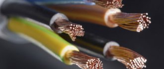
About the cross-section of wires coming out of the computer power supply
Although the currents that the power supply can supply to the load amount to tens of amperes, the cross-section of the output conductors, as a rule, is only 0.5 mm2, which allows current transmission through one conductor of up to 3 A. You can find out more about the load capacity of the wires from the article “On choosing a wire cross-section for electrical wiring.” However, all wires of the same color are soldered to one point on the printed circuit board, and if a block or module in a computer consumes more than 3 A of current, voltage is supplied through the connector along several wires connected in parallel. For example, voltage +3.3 V and +5 V is supplied to the motherboard via four wires. This ensures that up to 12 A of current is supplied to the motherboard.