Repairing a computer power supply yourself is quite a difficult task. Having undertaken this, you should clearly understand which of the components requires repair. Also, you should understand that if the device is under warranty, then after any intervention the warranty card immediately expires.
If the user has little skills in working with electrical appliances and is confident that he will not make mistakes, then he can safely take on such work. You should remember to be careful when working with electrical appliances.
Computer power supply circuit
The power supply is the most important and mandatory component of any system unit. It is responsible for generating voltage, which allows you to provide power to all PC units. Also, its important function is to eliminate current leakage and parasitic currents when pairing devices.
To create galvanic isolation, a transformer with a large number of windings is required. Based on this, a computer requires quite a lot of power and it is natural that such a transformer for a PC should be large and of considerable weight.
But due to the frequency of the current required to create the magnetic field, much fewer turns are required on the transformer. Thanks to this, when using a converter, small and lightweight power supplies are created.
The power supply is, at first glance, a rather complicated device, but if a minor breakdown occurs, then it is quite possible to repair it yourself.
Below is a standard power supply diagram. As you can see, there is nothing complicated, the main thing is to do everything one by one so that there is no confusion:
Diode characteristics
The diode itself, as a separate element, can be one of three types: a simple diode (pn junction), a microwave diode, and a Schottky diode (quantum). We are only interested in the last of them. The job of a diode is to pass current in one direction (and not pass it in the other). If the voltage drop in direct connection on conventional diodes is 1 or 2 volts, then on Schottky diodes it is close to zero. The voltages obtained in a computer power supply are low (12 Volts and 5), which is why only Schottky ones are used. You can see what the voltage drop across the diode is. The tester must be in “diode” mode (as mentioned above). If it “shows” from 0.015 to 0.7, then everything is correct. Such values are typical for a Schottky diode (less is a “breakdown”). Inside the power supply circuits, a pair of diodes is used, turning them on counter:
For positive voltage, “assemblies” are used (three-terminal, with 2 diodes in them). Single diodes (round body) - usually used to produce negative voltages. When replacing single diodes (even if one “flies”), it is recommended to replace them in “pairs”.
What is the best way to choose a replacement? If on the “rectangular” plastic case (3-pin) the brand is written:
Then, with “round” ones it will be more difficult. The stripe on the body only means “direction”. If we know the brand of diodes, we look for the same ones, or look at the parameters (voltage, current), and look for an analogue (with the same or slightly higher value). If we don’t know, well, you need to “download” the circuit diagram of your power supply and take a look. By the way, in the SC they also do this (but thinking and guessing what the current strength is is not a very rewarding task). Not forgetting that computer power supplies contain only Schottky diodes. Note: installing diode assemblies/diodes with obviously high current and voltage parameters is not recommended (let’s say: it was 50 Volts 12 A, but they install 50 Volts 20 A). There is no need to do this, because: there may be a different case. In addition, there are “additional” parameters (which in a more “powerful” case differ “not for the better”). Typical example (assemblies, low-power power supply): 12CTQ040 (40V, 12A); 10CTQ150 (150V, 10A). Example of single diodes: 90SQ045 (45V, 9A); SR350 (50V, 3A).
Necessary tools for repair
In order to begin repairing the power supply yourself, you should have the necessary tools on hand.
First you need to arm yourself with computer diagnostic tools:
- working power supply unit;
- post card;
- The memory stick is in working condition;
- compatible video card;
- CPU;
- multimeter;
To perform the repair itself you will also need:
- soldering iron and everything for soldering;
- screwdrivers;
- the computer is in working order;
- oscilloscope;
- tweezers;
- insulating tape;
- pliers;
- knife;
Naturally, this is not so much for a complete renovation, but this is enough for home renovation.
Step-by-step instruction
So, armed with all the necessary tools, you can begin the repair:
- First of all , you need to disconnect the system unit from the network and let it cool down a little.
- Unscrew all 4 screws that secure the back of the computer one by one.
- The same operation is carried out for the side surfaces. This work is done carefully so as not to touch the wires of the unit. If there are screws that are hidden under the stickers, they must also be unscrewed.
- After the housing is completely removed , the power supply unit will need to be blown out (you can use a vacuum cleaner). There is no need to wipe anything with a damp cloth.
- The next step is to carefully examine and identify the cause of the problem.
In some cases, the power supply fails due to the microcircuit. Therefore, you should carefully examine its details. Particular attention should be paid to the fuse, transistor and capacitor.
Often, the cause of power supply failure is swelling of the capacitors, which break due to poor performance of the cooler. This whole situation can be easily diagnosed at home. You just need to carefully examine the top of the capacitor.
swollen capacitors
A convex cap is an indicator of fracture. In ideal condition, the capacitor is a smooth cylinder with flat walls.
To fix this problem you will need:
- Remove the broken capacitor.
- in its place .
- The cooler is removed and its blades are cleaned of dust and other particles.
To prevent your computer from overheating, you should blow it regularly.
In order to check the fuse in another way, it is not necessary to unsolder it, but rather connect a copper wire to the contacts. If the power supply starts working, then it is enough to simply solder the fuse; perhaps it was simply moving away from the contacts.
To check the functionality of the fuse, just turn on the power supply. If it burns out a second time, then you need to look for the cause of the breakdown in other parts.
The next possible failure may depend on the varistor. It is used to pass current and equalize it. A sign of its malfunction are traces of soot or black spots. If such were found, the part must be replaced with a new one.
varistor
Note! A varistor is a computer part that is checked when it is turned on, so you need to be careful and attentive. Using a similar principle, each individual part is checked: diodes, resistors, capacitor.
It should be noted that checking and replacing diodes is not a very simple task. To check them, you should unsolder each diode individually or the entire part at once. They should be replaced with similar parts with the declared voltage.
If after replacing the transistors they burn out again, then you should look for the cause in the transformer. By the way, this part is quite difficult to find and buy. In such situations, experienced professionals recommend buying a new power supply. Fortunately, such a breakdown occurs quite rarely.
Another reason for PSU failure may be related to ring cracks that break contacts. This can also be detected visually by carefully inspecting the printed strip. You can eliminate such a defect using a soldering iron by performing careful soldering, but you must be good at soldering. If you make the slightest mistake, you can damage the integrity of the contacts and then you will have to replace the entire part.
ring cracks
If a more complex breakdown is detected, then excellent technical training will be required. Also, you will have to use complex measuring instruments. But it should be noted that purchasing such devices will cost more than the entire repair.
You should know that elements that require replacement are sometimes in short supply and not only are they difficult to obtain, but they are also expensive. If a complex breakdown occurs and repair costs exceed the price compared to purchasing a new power supply. In this case, it will be more profitable and reliable to purchase a new device.
Functionality check
After the reasons that brought the power supply out of operating mode have been eliminated, it must be checked.
The most basic operation is to turn on the computer to the network. But, by the way, this can be done without connecting a PC. It is enough to connect any load to the power supply, for example a CD-ROM, after which you need to short-circuit the green and black wires in the power supply connector and turn it on.
If everything is in order, then the fan and drive LED will immediately turn on on a working power supply. And naturally, the reverse reaction of the power supply (if nothing starts working), then the cause is not eliminated.
Once the serviceability of the device is confirmed, you can begin assembling the system unit.
How to get 12 volts from a computer power supply
As you already understand, taking the voltage from the computer power supply is quite simple. You only need to connect the device to the yellow wire (plus) and black (minus). Just be careful not to reverse the polarity, otherwise your device will most likely fail. Again, I repeat, do not forget that the power supply will supply voltage to the wires only when it is started. If you are working with a dismantled PC power supply that has been removed from the case, then you need to start the device by closing the GND (minus) and PWR SW wires.
Tips and tricks for repairs
Before you undertake independent repair of the power supply, you need to be fairly confident in your knowledge of electrical appliances:
- To begin with, you can read the literature, which can easily be found on the Internet, which describes in detail the causes and symptoms of power supply failure.
- We need to study the diagram.
- Before you begin disassembling the system unit, make sure it is unplugged from the network. It will be better if it is completely cooled.
- Dust and any dirt should be blown out using a vacuum cleaner or hair dryer. It is not recommended to use a damp cloth.
- The study should be carried out one by one of all details. It is advisable to check the operation of the power supply every time.
- If you don’t have the skills to work with a soldering iron , and you can’t do without soldering, it’s better to contact a specialist, it will cost less.
- If spare parts and repairs are more expensive than a new power supply unit, then it is better to think about purchasing a new part.
- Before you begin repairing the power supply, you need to make sure that the power cable and switch are in good working order.
Operating principle and main components
Before you begin repairing a power supply, you need to understand how it works and know its main components. Repairs to power supplies should be carried out with extreme caution and remember electrical safety during operation. The main components of the power supply include:
- input (network) filter;
- additional stabilized signal driver 5 volts;
- main driver +3.3 V, +5 V, +12 V, as well as -5 V and -12V;
- line voltage stabilizer +3.3 volts;
- high frequency rectifier;
- voltage generation line filters;
- control and protection unit;
- block for presence of PS_ON signal from the computer;
- voltage driver PW_OK.
The filter at the input is used to suppress noise generated by the power supply into the electrical At the same time, it performs a protective function during abnormal operating modes of the power supply: protection against overcurrent, protection against voltage surges.
When the power supply is connected to a 220-volt network, a stabilized signal with a value of 5 volts is supplied to the motherboard through an additional driver. The operation of the main driver at this moment is blocked by the PS_ON signal generated by the motherboard and equal to 3 volts.
After pressing the power button on the PC, the PS_ON value becomes zero and the main converter starts . The power supply begins to produce the main signals that go to the computer board and protection circuits. If the voltage level is significantly exceeded, the protection circuit interrupts the operation of the main driver.
To start the motherboard, a voltage of +3.3 volts and +5 volts is supplied to it simultaneously, from the power supply, to form the PW_OK level, which means the power supply is normal . Each wire color in the power supply corresponds to a different voltage level:
- black, common wire;
- white, -5 volts;
- blue, -12 volts;
- yellow, +12 volts;
- red, +5 volts;
- orange, +3.3 volts;
- green, PS_ON signal;
- gray, signal PW_OK;
- purple, standby food.
The power supply is based on the principle of pulse width modulation (PWM). The mains voltage converted by the diode bridge is supplied to the power unit. Its value is 300 volts. The operation of transistors in the power unit is controlled by a specialized PWM controller chip. When a signal arrives at the transistor, it opens, and a current appears on the primary winding of the pulse transformer. As a result of electromagnetic induction, voltage also appears on the secondary winding. By changing the pulse duration, the opening time of the key transistor, and therefore the magnitude of the signal, is regulated.
The controller, which is part of the main converter, is triggered by the enabling signal of the motherboard. The voltage enters the power transformer, and from its secondary windings it goes to the remaining nodes of the power source, which form a number of necessary voltages.
The PWM controller provides stabilization of the output voltage by using it in a feedback circuit. As the signal level on the secondary winding increases, the feedback circuit reduces the voltage at the control pin of the microcircuit. In this case, the microcircuit increases the duration of the signal sent to the transistor switch.
A filter is placed at the end of each power supply line. Its purpose is to remove parasitic ripples formed by transient processes of transistors. It consists, like any surge protector, of an electrolytic capacitor and inductance.
Signs of a broken power supply
In a vacuum, a power supply failure will not occur. If signs appear that indicate its malfunction, then before starting repairs, the reasons that led to its failure must first be eliminated.
Causes:
- Poor quality of supply voltage (voltage drops).
- Not very high quality components.
- Defects that were made at the factory.
- Poor installation.
- The arrangement of parts on the power supply plate is arranged in such a way that it leads to contamination and overheating.
Signs:
- The computer may not turn on , and if you open the system unit, you may find that the motherboard is not working.
- The power supply may work, but the operating system will not start.
- When you turn on the PC, everything seems to start working, but after a while everything turns off. This may trigger the power supply protection.
- The appearance of an unpleasant odor.
A faulty power supply cannot be missed, since problems begin with turning on the system unit (it does not turn on at all) or it turns off after several minutes of operation.
If at least one of the problems is noticed, you should think about eliminating the malfunction, otherwise, the computer may completely fail, and then you cannot do without the intervention of an experienced specialist.
Main problems:
- The most common thing that can affect the operation of the power supply is a swelling of the capacitor. Such a problem can only be determined after opening the power supply unit and fully inspecting the capacitor.
- If at least 1 diode fails , then the entire diode bridge fails.
- Burning resistors that are located near capacitors and transistors. If such a problem occurs, then you will need to look for the problem in the entire electrical circuit.
- Problems with the PWM controller. It is quite difficult to check; for this you need to use an oscilloscope.
- Power transistors also often fail. A multimeter is used to check them.
Note! Power capacitors tend to hold a charge for some time; therefore, it is not recommended to touch them with bare hands after the power is turned off. Also, you should remember that when the power supply is connected to the network, you do not need to touch the stove or radiator.
Real Power 400W Short circuit in the primary
So PSU Real Power 400W Field duty room 2D02N60Р, PWM SG6105DZ, Power Switches D209L
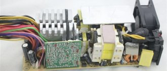
Upon receipt - fan jam => Chocolate-colored circuit board (heating and operation without a fan) => swollen condensers in the secondary + short circuit in the primary.
I replaced ALL the condensers with serviceable, good ones. I discovered a broken diode bridge in the primary - replaced it. I turn it on through a 75W light bulb. It works strangely - as if it starts up, it supplies voltage (all) to the mother, but they do not reach the maximum and turns off. And so it repeats in a cycle.
Repair cost
If you repair the power supply yourself and do not have the necessary tools at hand, then first of all you will have to spend money on buying them. This amount can reach from 1000 rubles to 5000 rubles.
As for the power supply itself, everything depends on the parts that have become unusable. On average, repairs can cost up to 1,500 thousand rubles.
Please note: a used power supply in good condition can cost 2000 – 2500 rubles. This applies to models for older computers. Modern PCs are equipped with more expensive power supplies.
At a service center, a similar procedure can cost about the same amount. But at the same time, you should remember that a specialist always gives a guarantee for his work.
Repair of alarm power supply, example
The home alarm power supply differs from a simple power supply in that it has battery backup power. Those. it connects to the battery and charges it as usual. But if the network goes out, it switches to autonomous battery power.
Let's give an example of a repair. In our case, the power supply did not provide supply voltage for signaling. It was done on a separate board, which is convenient for repairs.
The primary circuits all worked. But the output was 0. Moreover, there were no visible signs of a malfunction. Even the key transistor was intact.
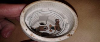
It turned out that capacitor 1 in the PWM regulator circuit 2 was faulty. Externally, the electrolytic capacitor was absolutely normal. But in the soldered state, the tester diagnosed it as an unknown device.
After replacing the capacitor, 1 power supply immediately started working. Repair price 2000 rub.
Design of switching power supplies, diagnostics and repairs here.