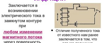
The concept of magnetizing current
The sudden increase, that is, the inrush of the magnetizing current (BCT), is explained by the saturation of the core by magnetic induction. Transformers are dynamically resistant to surges due to the manufacture of windings taking into account large currents, as a rule, arising from short circuits. On average, the magnetizing current exceeds the rated value of the device by 6-8 times.
Rice. 1. Conditions for the appearance of BTN
In short circuit mode, the voltage of the power unit is characterized by an extreme decrease to zero, and after disconnecting the damage zone, it is established at the terminals of the device in an abrupt manner.
The restoration of the magnetic flux occurs unevenly and not immediately, which causes the occurrence of a transient process, during which two fluxes are formed - a steady FU and a free FSV. To determine the total value, the formula is used:
FTO = FU + FSV
At the reference point, which characterizes the initial moment of time at t = 0, the FTO is also equal to zero, so the equality FSV = – FU seems fair. The signs of the polarity of magnetic fluxes coincide in the second half-cycle, and, accordingly, the resulting value reaches a peak maximum (FTmax).
Rice. 2. Magnetic fluxes in the core under load
Schematically, there is a lag of FU from UT by 90 degrees, which indicates the dependence of FSV and FTmax on the voltage phase. These values reach their highest values when turned on - at the moment UT passes through zero. If we do not take into account gradual attenuation, FTmax ≈ 2FU. But the peak flux value can be higher when there is residual magnetization Fost in the core thickness, which coincides in sign with FSV.
Then:
FTmax = (2FU + Fost)> 2FU
The core is saturated at flux values close to 2FU, causing a sharp surge in In. The magnetizing current is generated only in the winding of the circuit to which voltage is applied when turned on. It is converted through a protective device and enters the relay, causing it to operate subject to the inequality Iam > Is.z..
Three-phase transformer with Y/Δ connection
Let a winding connected by a triangle be connected to a network with a sinusoidal voltage at idle (Figure 3, a). In this case, each phase of this winding will be connected to the sinusoidal mains voltage. Consequently, the flows of each phase will also be sinusoidal, and the magnetizing currents of phases i0ra, i0rb, i0rc, like a single-phase transformer, will contain odd higher harmonics. In each phase, the higher harmonics of the current will be located relative to the main harmonic of the current in an identical manner (Figure 4).
| Figure 3. Power supply of a transformer with a Y/Δ winding connection at no-load: a – from the side of the winding connected in a triangle; b – from the side of the winding connected in a star | Figure 4. Reactive components of the magnetizing current and its harmonics in individual phases of a delta-connected transformer winding |
However, while the fundamental harmonics of the individual phases will be shifted relative to each other by 120°, the third harmonics will be shifted by 3 × 120° = 360° or 0°, the fifth harmonics will be shifted by 5 × 120° = 600° or 240°, the seventh – at 7 × 120° = 840° or 120°, ninth – at 9 × 120° = 3 × 360° or 0° and so on.
Thus, harmonics that are multiples of three (v = 3, 9, 15...) will be in phase in individual phases of the winding. For this reason, in linear currents, which represent the difference between the currents of the corresponding phases, harmonics that are multiples of three will be absent. Therefore, the currents of these harmonics will circulate inside a closed triangle (Figure 3, a), and, being equal in value and coinciding in phase, they form a common closed circulating current.
If a transformer with a Y/Δ winding connection is powered at no-load from the side of the winding connected in a star (Figure 3, b), then harmonics that are multiples of three cannot exist in the phase currents, since they must be in phase and at the same time their sum must be equal to zero, since there is no current exiting the zero point. However, as was clarified above in connection with the consideration of the process of magnetization of the magnetic circuit of a single-phase transformer, in the presence of saturation, in order to obtain a sinusoidally varying magnetic flux, the magnetizing current must contain harmonics that are multiples of three. Since in the case under consideration the presence of such current harmonics is impossible, the flow will be non-sinusoidal.
| Figure 5. Shape of the flux curve for a sinusoidal magnetizing current (a) and vector diagram of fluxes and third harmonic currents (b) |
In the absence of harmonics that are multiples of three, the current i0r will be close to sinusoidal (Figure 5), since the harmonics v = 5, 7... are relatively small. With this form of current i0r, the curve of the flux ФY created by a winding connected in a star, due to saturation, will have a flattened or blunted shape at the top (Figure 5, a). Such a flow curve, along with the main harmonic Ф1Y, will also contain a relatively strong third harmonic Ф3Y. The third harmonics of the flux Ф3Y of all three phases are in phase and will induce in the secondary winding connected by a delta, three equal in value and in phase e. d.s. E3Δ (Figure 5, b). Folding in the contour of a triangle, these e. d.s. create a current I3Δ in this circuit, which, due to the predominance of inductive reactance, will be almost purely inductive. The Ф3Δ flows created by this current will almost completely compensate for the Ф3Y flows. Therefore, the resulting phase flows will be practically sinusoidal. Thus, compared to the supply from the side of the winding connected by a triangle, the difference lies practically only in the fact that the third and multiple harmonics of the magnetizing current arise on the secondary side (Figure 3, b).
From the above it follows that in the case of one of the transformer windings connected in a triangle, the magnetic fluxes, e.g. d.s. and the phase voltages remain sinusoidal. This circumstance constitutes a significant advantage of three-phase transformers, in which one of the windings is connected in a triangle.
The above applies equally to both group three-phase transformers and three-phase transformers with a common magnetic core.
Why does the surge occur when turned on?
A short-term jump is characterized by an inrush of the magnetizing current of the transformer (BTC). Its values on the same device may differ in value for different switching ons. The reason for the formation of BTN in power devices is a sudden change in the magnetizing voltage level. In addition to the load transferred to the winding, the surge can be caused by other reasons:
- external short circuit (SC);
- restoration of voltage in the circuit;
- short circuit transformation;
- non-synchronous connection of the generator.
The magnetizing current introduces an imbalance at the transformer terminals. The device protection perceives the BTN as a differential current. But in order for it to correctly fulfill its purpose, the system must function effectively and be configured taking into account the BTN by including auxiliary devices such as intermediate transformers in the circuit.
To prevent surges from affecting the operational life of the unit, it is undesirable to allow the transformer to turn off as a result of surges.
When the winding is turned on at full load, due to asynchronous power distribution and transient wave processes, a high overvoltage occurs, which can cause an internal short circuit.
Important! Overvoltages due to BTN are safe only if the differential protection of the system is properly organized.
How the process works
When a load is applied, the magnetization of the device due to switching on is considered as a negative phenomenon that can provoke a BTN of maximum amplitude. When turned off, the magnetizing current is reduced to zero, and the magnetic induction is adjusted depending on the degree of magnetization of the steel core, as a result of which residual induction remains in the magnetic circuit.
If after a while the current-converting device is switched on again under a voltage subject to the sinusoidal law of change, the magnetic induction changes with a displacement of the residual value up to 90% of the nominal value. The result is a high magnetization amplitude and a change in the shape of the curve.
Rice. 3. Classic type BNT curve
The magnetizing current level decays within tenths of a second, but complete “smoothing” of the curve occurs within a few seconds, and under certain conditions – after a few minutes. The duration of attenuation of the aperiodic component of the BTN oscillogram is due to the high amplitude of the current at the initial (zero) moment of time and the content of various harmonics. The peak value depends on the load voltage and its parameters, as well as on the value and polarity of the residual magnetic flux in the core.
The peak current can be 10-15 times higher than the rated value for high-power units, and 20-25 times higher for devices with power (<50 kVA). The decay period ranges from a few milliseconds to seconds.
1. The process of magnetization of the transformer magnetic circuit
ABOUT THE NATURE OF ELECTROMAGNETISM
ZOLOTUKHIN V. A.
1. Introduction
While working on his future “Electromagnetic Theory”, D. Maxwell could not find the carrier of interaction he needed between the alternating magnetic flux and the emf induced in the coil. After much thought and hesitation, D. Maxwell, relying on the apparent symmetry of electrical and magnetic phenomena and the advice of K. Neumann, artificially introduced the so-called into his theory. “vortex electric field”, providing it with properties that ensure the possibility of mutual reversibility of electric and magnetic fields, which are absolutely necessary for him to create the mathematical apparatus of his theory... Over the course of one and a half hundred years of its development, electromagnetic theory has turned, with someone’s “light hand”, into “ phenomenological" (divine) and "fundamental", reliably fenced off from any encroachment on oneself with their statuses.
But, any theory remains infallible and true until at least one fact of practical experience is discovered that contradicts this theory, one single doubt about its reliability. This should alert us, make us take a closer look at what is considered the absolute truth.
And there are such doubts...
Modern Physics knows a lot about the world around us, but not everything. So, for example, Physics does not know what time is, gravity, what an electron is, what a magnetic field is...
And what is known and considered an “immutable truth” sometimes requires more careful study and rethinking. Here's an example:
2. Transformer paradox
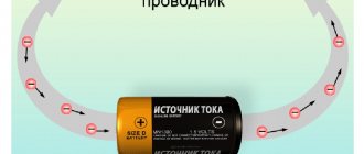
Let's take a look at the long-known electromagnetic device - the transformer (Fig. 1):
Fig.1
Knowing its operating principle, you can easily trace the chain of energy transformations in it: the electrical energy Ee in the primary winding
w 1 of the transformer is converted into the energy Em of the magnetic flux F of the core, which in the secondary winding w 2 of the transformer is again converted into electrical energy E E
(Fig. 2).
Fig.2
Now let's consider this energy chain in dynamics:
EE can vary within very wide limits - from 0 to EE max. Accordingly, from 0 to Em max, Em should also change synchronously - we have the right to expect this, because Em is a link in the energy chain of the transformer. But the theory (and the real fact) says that the magnetic flux of a transformer, and accordingly its energy, is a constant value and in no way dependent on the level of energy passing through the transformer. Thus, the logical energy chain of operation of the transformer that we have built does not agree with the theoretical premise about the role of the magnetic circuit in the general structure of the transformer. We are observing a violation of cause and effect relationships ,
those.
PARADOX.
And no matter how strange and truly paradoxical this may seem, we have to admit:
the magnetic flux in the transformer core does not take part in the transfer of energy through the transformer.
The revealed paradox immediately entails the following inconsistency: around the alternating magnetic flux, according to classical concepts, a “vortex electric field” arises and it is this that creates the EMF in the turns of the secondary winding. It turns out that the vortex electric field also does not participate in the appearance of energy in the secondary winding!??
3. The inductor paradox
If the “Transformer Paradox” has not shaken your “holy” faith in the infallibility of electromagnetic theory, and specifically, in the theory of the transformer, here’s another example:
Let's consider an alternating current circuit with inductance L (Fig. 3). According to the existing theory, a counter-EMF is created in the L coil. – UL, equal in value to the mains voltage, but directed counter to it – the so-called balancing E.M.F. or E.M.S. self-induction.
Rice. 3
But in this case the voltmeter V
should show zero or a value close to zero.
The device always shows the network voltage U c .
Why? And under what force, in this case, does the current flow in the circuit, since the voltages are balanced?
4. Transformer effects
We connect a conventional two-winding transformer to an alternating current network. In the circuit of the primary winding ω1 we will turn on the light bulb L1, and in the circuit of the secondary winding ω2 we will turn on the light bulb L2. Let's agree that the light bulbs burn at full intensity. Let us equip the transformer with a third winding ω3, covering the entire transformer.
Fig.4
When an alternating voltage Uy is applied to the winding ω3 from a third-party source of the same frequency, we find that, depending on the magnitude of the voltage Uy or the phase between the voltages Uy and Uc, the lamps L1 and L2 either go out or flare up to full brightness. Thus, we discovered the effect of influence
“illogical” winding ω3 on the operating mode of the transformer.
When manipulating the types and arrangement of windings ω1 and ω2 on the magnetic cores, it turns out that the influence effect breaks down into 2 parts:
Synchronous effect
– lights L1 and L2 go out or light up simultaneously;
Asynchronous effect
– one of the lights goes out, while the other lights up;
Meanwhile, there is such a design and location of the windings when the influence effects do not appear at all.
If voltage Uy is not applied to the “illogical” winding ω3, but a measuring device – a voltmeter – is connected to it, then we will detect a generator effect ,
which, again, depending on the design of the windings and their location, breaks down into:
1) Directly proportional generator effect
– in an “illogical” winding, an EMF is generated (and power is released) directly proportional to the power passing through the transformer.
2) Inversely proportional effect.
And just as in influence effects, there is a case when generator effects do not arise at all.
The change in the brightness of the glow, at least of the lamp L1 in the influence effects, can be explained by only one thing: the effect of a change in the inductance of the primary winding ω1 of the transformer is observed.
Those. winding inductance
transformer (choke), obtained as a fact during its manufacture,
changes
(adjustable) both towards decrease and
towards increase?!!
from its face value .
5. How a magnetic field is generated
To move forward, we only need to make one assumption:
The magnetic field is generated by accelerated moving electrons and spreads in space by sequential mechanical movement; the magnetic field on the same parent electrons collapses when the latter are decelerated. In other words, an electron and a magnetic field form a rigid mechanical system.
Note - the ability of a field to move in space is a necessary condition for generation to occur.
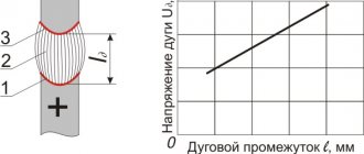
Let's remove the core from the transformer and test it for performance. There is no energy transformation. There is a characteristic curve on the oscilloscope screen (Fig. 5)
Rice. 5
Sharp peaks indicate the moment of disruption of the magnetic field generation - the destruction of the mechanical system “electron - magnetic field”
– there is
a “slippage” of the field on electrons.
The reason is the “magnetic pressure” in the current-carrying circuit of the winding, the rigidity of the
“electron – magnetic field”
is not enough to generate and “pack” into the circuit the required number of lines of magnetic induction field.
With this simple experiment, we transferred our assumption to the category of “Assertion”.
6. How does a transformer work?
The transformer paradox, as well as the conclusions that follow from it and contradict all the canons of electrophysics, force us to reconsider the operating principle of a conventional transformer.
Any set of interrelated events can be considered in the dynamics of their development over time, even those occurring seemingly simultaneously. The principle of causality allows us to do this, according to which any considered set of events can be divided into two groups: “events - causes” and “events - consequences”
and, therefore, allows you to correctly, in strictly chronological order, place them on the time axis.
It is worth especially noting that “event – cause” and “event – effect” cannot occur simultaneously, there must be a time gap between them, and “event – effect” will never and under no circumstances happen before “event – cause”.
To make it easier to understand the essence of the processes in a transformer, we use a “time lens”
— let’s stretch the time scale (axis) of events occurring with the transformer during its operation, and consider all these events step by step.
a) The appearance of current in the primary winding (
in the figures the windings are shown in the form of sections of turns) causes in the part of the transformer magnetic circuit located inside the winding a reorientation of the magnetic fields of the domains along the resulting magnetic field.
In Fig. Figure 6 shows the magnetic field induced (initiated) by the current of the primary winding. Let's give it the name “reference field”
.
Fig.6
c) Reference induced by the current of the primary winding
The magnetic field, due to the ordering of the magnetic fields of the domains, sharply intensifies (many thousands of times) and begins to expand in two directions at once - along the upper and lower yokes of the magnetic circuit (shown by arrows) - a “chain reaction” of reorientation of the magnetic fields of the magnetic circuit domains has begun, Fig. 7.
Rice. 7
c) The chain reaction of reorientation of the magnetic fields of the magnetic core domains continues, the length of the resulting field continues to increase. Rice. 8.
Rice. 8
d) The chain reaction of reorientation of the magnetic fields of the magnetic core domains continues, the length of the resulting field continues to increase. Rice. 9.
Rice. 9
f) The chain reaction of reorientation of the magnetic fields of the magnetic core domains continues, the length of the resulting field continues to increase. Rice. 10.
Rice. 10
f) The final stage of development of the magnetic field in the magnetic circuit of the transformer. The entire volume of the magnetic circuit is magnetized. The magnetic field has the maximum degree of development - the greatest length of the magnetic induction lines. Rice. eleven.
Rice. eleven
When the current in the primary winding decreases, the reference field initiated by it begins to contract and curl up on the electrons of the metal of the primary winding - after all, it was the movement of electrons in it that generated it. But the collapse of the reference field inevitably causes the collapse of the magnetic field induced in the magnetic circuit in a sequence reverse to development. Rice. 11, 10, 9, 8, 7, 6
Video “Traveling magnetic wave” https://www.youtube.com/watch?v=bfda1_unk98
First
, which catches the eye when considering the step-by-step pictures of magnetization and demagnetization of a magnetic circuit -
“a magnetic field is capable of moving in space” -
a beam of magnetic induction lines moves in the space of a magnetic circuit window (magnetic wave).
Modern physics denies the possibility of moving magnetic fields; its magnetic field does not come to a given point in space, but miraculously “appears” and “disappears” at it.
Second
- the appearance of an electromotive force in the turns of the secondary winding is very easily and simply explained by the well-known Lorentz force arising on the electrons of the metal of this winding - it is this force that displaces the electrons to one of the terminals of the winding, creating an emf. when the turns are crossed by a magnetic wave.
Modern physics explains the emergence of emf. in the secondary winding of the transformer by a hypothetical “vortex electric field”.
Third
-
the paradox of the transformer has disappeared
- now we know that
the magnetic flux of the transformer core really does not participate in the process of transferring energy
from the primary winding to the secondary,
the energy carrier is magnetic induction lines
-
a magnetic wave moving in the window of the magnetic circuit.
But the magnetic circuit of the transformer is a necessary condition for the operation of the transformer, which performs two functions at once:
1) – is a motor that moves a magnetic wave in the window space,
2) – is a container, the final storage warehouse for the accumulation of a developed magnetic field.
Fourth
– we are convinced that the source of energy arising in the secondary winding of the transformer can only be the energy of a moving magnetic field.
But then there must be a source of its replenishment and, according to the simple logic of things, this can only be the electric current in the primary winding. A solution to the question immediately arises - the moving electrons of the primary winding generate a magnetic field, and this field collapses on them.
Realizing that the magnetic field is nevertheless generated by an electric current, it is not difficult to determine the condition for the generation of a magnetic field by electrons - this can only be the accelerated movement of electrons, the condition for the curtailment of the field is the braking of electrons.
7. Energy transformations in a transformer
The processes of generating and collapsing the magnetic field are accompanied by the extraction of energy from the network and its subsequent return to the network. This is the idle mode of the transformer. From the established idle mode it follows that the transformation energies must be equal: the amount of energy spent by the network on generating the magnetic field is equal to the amount of energy received by the network from its folding (we will not take into account losses due to magnetization reversal of the magnetic circuit, in this case it is not important).
The process of generating a magnetic field is accompanied by opposition from the primary circuit of the transformer to the power source; we know this opposition as “inductive reactance”
.
When the magnetic field collapses on the electrons of the primary winding, electrons are “spiked”
(energy is returned to the network), which is qualified in classical electrical engineering as
E.M.F.
self-induction. The appearance of current in the secondary circuit of the transformer leads to an imbalance of transformation energies, because The magnetic field gives part of its energy to the electrons of the secondary winding (to the secondary winding network). The energy shortage during field collapse is immediately compensated by selecting the appropriate amount from the supply network. The balance of transformation energies is restored.
Thus, replacing the concepts of “appearance” and “disappearance” of a magnetic field, which are devoid of any physical meaning, with the concepts of “generation” (in the first quarter of the period of the current graph
Im sin ωt ) and “collapse” (in the second quarter of the period), we described the principle of operation transformer without inventing new fields and particles.
We just looked at what has long been known from a different angle. At the same time, the following became clear: 1. The paradox of the transformer disappeared
– now we know that the magnetic flux of the transformer core really does not participate in the process of transferring energy from the primary winding to the secondary winding; the energy carrier is a moving magnetic field (wave) in the space of the magnetic circuit window.
2. E.D.S. in the secondary winding of the transformer is created by the well-known Lorentz force.
3. No so-called balancing E.M.F. (E.M.F. self-induction) in an alternating current circuit with inductance there is no.
Let me remind you of the classic picture (Fig. 3):
UL does not exist, but the voltmeter proves this, because.
always shows the network voltage Uc , and it cannot be accused of bias.
When considering the principle of operation of a transformer, we did not have to resort to the concept of “vortex electric field” as unnecessary.
8. Experience in detecting the fact of magnetic field movement in space, forecast graph and oscillogram
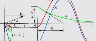
The ability of a magnetic field to move in space requires high-quality instrumental confirmation. Let's find out the shape of the graph of magnetic field speeds, taking as a basis the graph of the current in the primary winding - Im sin ωt. (Fig.12)
Fig.12
It is quite obvious that for all zero current values in the primary circuit, the future graph of the magnetic field speeds will also have zero values. At the maximum points, when the acceleration of electrons is zero, the speed of movement of the magnetic field will again be equal to zero. Thus, after every quarter of the period the velocity graph should have zero values. In each such section, limited by zero values, the speed of the magnetic field should increase from zero to a maximum value and decrease again to zero. In the second half of the period of the current graph, the velocity graph will also be located under the time axis—the direction of the field changes. As a result, an approximate shape of the graph is formed - it looks like a kind of double-humped sinusoid (see Fig. 13). But the author was unable to find analogues of the curve obtained on the oscillogram either in mathematics or in physics.
Fig.13
9. Electromagnetic devices with new properties
The version about the generation and folding of a magnetic field turned out to be very successful, because logic-defying transformer paradox
and
back-EMF
have disappeared, and the transformer continues to work properly without involving the concept of
“vortex electric field”.
Based on the accepted version, the author predicted and found in practice more than a dozen effects on transformers that had not been described anywhere before by anyone.
Five of the group of effects found were registered by the author in the form of RF patent No. 2138872, and it was he who, in fact, became the author’s priority reference.
The fact of finding predictive effects, eliminating contradictions in the theory and the oscillogram of the key experiment - all this together is sufficient and, I believe, irrefutable evidence of the validity of the accepted version of the nature of electromagnetism, the properties of the magnetic field and the fictitiousness of the very concept of “vortex electric field”.
Based on several undeclared effects, transformers and chokes were designed with new properties inaccessible to classical electrical engineering. Here is a short list and scope:
The inductor does not introduce any distortion into the regulated signal (sinusoidal) and does not require special DC power supplies for the control circuits.
Scope of application – deep stepless regulation of high-current processes: starting electric motors with a high-power wound rotor, current regulation in electrometallurgy, in the electrolysis of metals, in welding production, in regulating the brightness of airport runway lights...
The use of adjustable chokes will completely eliminate the use of powerful
power thyristors, will simplify power supply circuits, reduce the number
maintenance personnel will generally increase the reliability of the equipment.
Video “Choke Inductance Regulation”
Based on this transformer, it is possible to create an “electromagnetic
voltage stabilizer”
, unknown to modern electrical engineering, and characterized by a lower cost compared to modern stabilizers with thyristor and relay control.
When equipping any electrical substation with a booster adjustable transformer, we obtain a stabilized electrical substation
, there are no restrictions on the power transmitted by the voltage booster transformer. There are no semiconductor devices in the design, which increases the overall reliability of the devices.
There is no such concept in classical electrical engineering.
Video "Split Transformer"
Application area
– voltage-regulated AC power supplies for all kinds of purposes, for example –
replacement of universally used, but dangerous in operation, LAtr.
By analogy with a mechanical device, we can say: an electric “power take-off shaft”.
It is connected to a break in the network supplying any object. Inductive and active resistance are close to zero. The voltage removed from it is regulated, the main and dependent networks are galvanically isolated.
5. Wireless power transmission devices, for example to power drones.
10. About some non-obvious properties of an alternating magnetic field
Let's summarize what we have learned about the magnetic field:
1. A magnetic field is capable of moving in space.
2. The magnetic field is generated quickly
moving electrons and folds only on these same, “parent” electrons when they slow down.
3. Magnetic fields cannot collapse on “foreign electrons” that did not generate them, but interact with them according to known rules (Lorentz force).
4. There are no material screens for the magnetic field. To confirm this, we will conduct a simple experiment - we will make the windings of the transformer with shielded wire, we will make the central cores the working part and we will test the transformer in operation. The transformer is working properly. Let's replace the mesh screen with a solid thick-walled copper tube. The transformer continues to work properly.
We will replace the copper tube with a steel one. No visible changes in the operation of the transformer were detected.
The general conclusion from these experiments is that the penetrating ability of the magnetic field is unique - there are no material screens for it! Warn
its distribution in space is possible only by coupling in a ferromagnetic circuit - the case of a transformer. Shielding any object from variable external magnetic fields is a rather difficult task.
5. Separate experiments have established the ability of an alternating magnetic field to focus at a given point in space.
11. About the vortex electric field
We already know that the transformer works perfectly without using the concept of “vortex electric field”.
To this day, Physics believes that a magnetic field is not capable of moving in space, and energy in space can only be transmitted by an electromagnetic wave, a kind of symbiosis of magnetic and electric vortex fields.
Ask any specialist in electromagnetic theory to explain “what is an electromagnetic wave?”... And any of them will immediately begin to draw 2 flat sinusoids located at right angles to each other.
A physical object is replaced by a mathematical concept!!!
Why is this happening? Yes, only because
It is impossible
to depict something that does not exist in reality.
Most likely, the concept of “vortex electric field” was introduced into the mathematical apparatus of electromagnetic theory artificially, to theoretically ensure the possibility of energy transfer in space.
Knowing about the ability of a magnetic field to move in space, you can easily understand how a conventional television antenna, for example, a half-wave vibrator, works - the signal is generated, again, by the well-known Lorentz force.
12. Magnetic field of the solenoid
Look at the pictures from Yandex.Pictures
:
This series can be continued for a very, very long time...
And everywhere, in any picture, it is clear that the magnetic field in the solenoid is uniform,
in the descriptive part of each picture this is certainly indicated, and often mathematical calculations confirming this are also given.
But it is also known from the school physics course that magnetic field lines of the same direction and lying in the same plane cannot be brought together. For this reason, the diametrically located magnetic field lines of the solenoid with current simply must be located at a certain distance from each other, creating an axial cylindrical channel in the solenoid, absolutely free from the magnetic field. Experiments fully confirmed this assumption. Thus, the statement
about the uniformity of the magnetic field in a classical solenoid is, to put it mildly, erroneous.
Knowledge of this fact, as well as several others accompanying it, allowed the author to obtain an oscillogram of magnetic field velocities - a “double-humped sinusoid”.
The picture will change dramatically if a ferromagnetic core is placed in the solenoid - the magnetic field will become truly uniform over its entire cross section
13. DC magnetic field paradox
Any person with a high school background knows that an electric current in a conductor generates a magnetic field. But the electric current in a conductor consists of electrons moving unidirectionally, and we have the right to expect that the magnetic field generated by these electrons will also move synchronously with the electrons.
But it was not there. In any publications, the direct current magnetic field is stationary!!!
Once again (remember the transformer paradox) we observe a break in cause-and-effect relationships -
a paradox
.
If the magnetic field is stationary, then, in the author’s opinion, it is necessary to talk about the magnetic field as “the reaction of space to the “penetration” of it by a moving electron” with all the options for developing the question that follow from this assumption...
If the magnetic field moves synchronously with the electrons generating it, then it is necessary to prove this by experiment.
And such an experiment, qualitative, not quantitative, was carried out by the author. The result is a direct current magnetic field that is mobile and moves synchronously with the electrons.
I do not provide a description of the experiment or video footage, considering this to be premature, but the experience itself and the methodology for carrying it out are my own know-how
…
14. Summary
Based on the results of experiments, partially included in this article, new properties of the magnetic field, previously covered by the concept of “vortex electric field”, were revealed:
1. The magnetic field is born (generated) accelerated
moving electrons and disappears
by curling up
on the same electrons when the latter are slowed down -
the electron and the magnetic field form a rigid mechanical system
. The ability to move a field in space is a necessary condition for generation to occur.
2. The magnetic field can be focused to a given point in space - this, in fact, is a consequence of its ability to move.
3. The magnetic field has the highest penetrating ability, there are no material screens for it, stopping (preventing) its movement is possible only by binding it in a closed ferromagnetic circuit (the case of a transformer) or, partially, in a given area, with a flow of electrons - electric current.
4. When considering the principle of operation of a transformer, there was no need to resort to the concept of “vortex electric field” as unnecessary
.
Hence the conclusion - the so-called. “vortex electric field”
does not exist
as a physical reality Author Zolotukhin Vladimir Alekseevich
PS The article “On the Nature of Electromagnetism” is a revised journal version, the evidentiary part and several chapters that reveal the real possibilities of creation have been partially removed from it:
1. Wireless communications over strictly regulated distances
2. A fundamentally new method of protection against electromagnetic radiation
3. Energy channel in space
The article is protected by RF patent No. 2138872
Methods of blocking on the secondary winding
There are several ways to eliminate false positives on BTN. The effectiveness of the method of slowing down protection (disadvantage - loss of performance), braking, blocking, which did not give good results, was experimentally tested. The most rational methods of detuning from magnetizing currents are:
- Use of fast-saturating transformers.
- Adjustment of differential cutoff.
The methods have proven their effectiveness in practice, are distinguished by high reliability, simplicity and preservation of the most important protection parameter - speed.