The concept of rated power of a transformer
The rated power of a transformer is the total power for which the device is designed by its manufacturer. That is, the voltage that the transformer can withstand without interruption throughout its entire service life.
Factories provide a service guarantee of 20 to 25 years.
This indicator is always related to the operating temperature: how much heating of the windings is allowed and under what conditions the unit is cooled. For different powers of the transformer windings, the rated one is considered to be the highest. Basically, transformers are equipped with oil cooling, which directly depends on the ambient temperature.
Since weather conditions are constantly changing, the greatest heating of the windings at maximum air heat is considered the upper limit of the average temperature resistance that is possible to maintain safety.
For devices with a different type of cooling, the manufacturer’s passport specifies the nominal temperature conditions.
In addition to the rated power, there is a typical power of the transformer, which is calculated as the sum of the load values on all windings, divided by two. And the maximum load on the windings is calculated as the product of the maximum current value and the maximum permitted voltage of a given part of the circuit.
Heat removal system
During the conversion of electricity, part of the losses is released in the form of heat, so a heat removal system is invariably present in any PT. Powerful devices are equipped for this purpose with a special dual-circuit system, in which the oil is cooled in the following ways:
- By means of radiators (see E in Fig. 4), which provide heat removal to the secondary or external environment.
- Tank housing with a corrugated surface (used in low-power devices).
- Installation of ventilation equipment. This solution allows you to increase productivity by a quarter.
Fans of the forced cooling system ST - Additional water cooling systems. This is one of the simplest and most effective ways to remove heat.
- The use of special pumps that circulate oil in the heat removal system.
Operating voltage control devices
In some cases, it becomes necessary to increase or decrease the CT load voltage; for this purpose, most designs provide a special switch. Essentially, it changes the transformation ratio by switching to more or less turns in the coils.
As a rule, such manipulations are performed when the load is removed, but there are devices that allow you to change the CT without disconnecting consumers.
Types of additional equipment
To ensure stable operation and maintenance of CTs, their design may include the following devices, called attachments or additional equipment:
- The gas pressure switch is a protective system. If the CT goes into abnormal operation mode, then as a result of large heat release, oil decomposition occurs. This process is accompanied by the release of gas. When it forms quickly, a protection is triggered, disconnecting the device from power and load. If the gas formation process is slow, an alert is activated.
- Thermal indicators show the heating of the oil in various components of the heat removal system.
Oil temperature indicator - Desiccants. They are used in non-sealed oil heat removal systems and prevent the formation of water condensation.
- Oil regeneration systems.
- Pressure sensors, if it exceeds a certain threshold, the reset device is automatically turned on to normalize.
- Oil fill level sensor in the heat removal system.
What is measured and indicated?
The power rating of transformers is measured in kVA (kilovolt-amperes), not kW (kilowatts). These two indicators are different and not identical. The first is the total (nominal) power, the second is the active. The rated power is not consumed in full, since part of it is distributed to the electromagnetic fields of the circuit, and only the remaining part - this is the active power - acts as intended.
The load on a transformer is determined by the current consumed, not the energy that is actually used. That is, the total power represents the entire voltage applied during operation of the device to all components of the electrical chain. Therefore, this nominal value is indicated in volt-ampere units.
In the operation of electrical appliances, a coefficient is also taken into account, which is expressed in the ratio of active to nominal (cos phi). This coefficient reflects the magnitude of the phase shift of the alternating current relative to the load applied to it.
Design features
Despite the variety of types of CT, their design invariably includes the following mandatory elements:
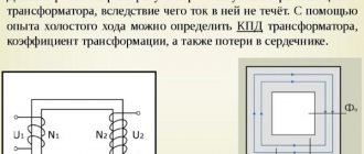
- outputs of high and low voltage coils (HV and LV), they are usually called power inputs;
- heat removal system;
- devices that allow you to regulate the operating voltage;
- additional equipment for monitoring the operation and maintenance of the device.
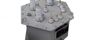
The figure below shows a typical CT design with an oil heat removal system.
Oil Cooled Power Transformer Design
Designations:
- A – expansion tank, serves to level the oil level when its volume changes due to temperature fluctuations.
- B – power input for HV.
- C - input for NN.
- D – operating voltage switch.
- E – radiator, consists of pipes through which oil circulates.
- F – housing, also plays the role of an oil tank.
- G and H – HV and LV coils.
- I – magnetic conductive core.
Now we will consider in detail the purpose of the main structural elements.
Purpose of power inputs
This design element is necessary to connect power and load to the CT. Their location can be either internal (closed terminal blocks) or external. Please note that the first arrangement option is used only in STs with an air heat removal system.
It is necessary to have insulation between the input and the housing; it can be oil barrier, SF6, capacitor-through, or made of materials that do not conduct electricity (porcelain, polymers, etc.).
Rice. 4. Porcelain insulators on the power transformer inputs
Standard power scale for power transformers
On the territory of Russia, a single scale of standard capacities is used. It is divided into two steps: 1.35 and 1.6, each including a number of values presented in the table below.
| Step 1.35. In kVA | Step 1.6. In kVA |
| 100 | 100 |
| 135 | 160 |
| 180 | 250 |
| 240 | 400 |
| 320 | 630 |
| 420 | 1000 |
| 560 | 1600 |
Currently, factories produce transformer substations (TS), using power steps of 1.6. The 1.35 pitch scale is no longer used in production, but old installations produced in Soviet times were designed precisely according to this scale. At the same time, studies have identified older devices as more profitable because they can work at full capacity, unlike modern units.
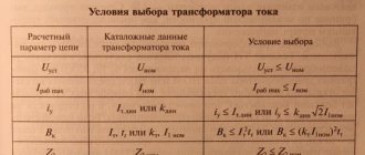
When choosing different types of devices, it is taken into account that they should be as close as possible in terms of the highest load indicator in normal mode and the maximum voltage in emergency mode.
When choosing transformers for industrial production, it is important to take into account their number for rational distribution of electricity and their typical power at a certain rated load.
Accepted markings
The alphanumeric designations of ST are made in accordance with the figure below.
Power transformer marking
Designations:
- The type of device is indicated. Options “A”, “L”, “E” or no symbol are possible, which corresponds to an autotransformer, linear or furnace device. The absence of a symbol indicates a regular ST.
- “O” or “T” corresponds to a single-phase or three-phase device.
- Heat removal option used (for oil systems), possible options:
- M – compulsory systems are not used.
- D – forced airflow is performed.
- DC – forced airflow with non-directional circulation is performed.
- NC – water-oil cooling with directed circulation.
- C – water-oil cooling with non-directional circulation.
- Indication of power in kV*A.
- Permissible HV level (kV).
- Execution option (external or internal placement, special climatic conditions, etc.)
Transformer selection example
You can select a transformer based on their design, focusing on the required characteristics, or on the basis of the rated load.
Selection by design
Power transformers come in several types:
- oil - installed inside or outside buildings where there is no danger of fire or explosion of substances;
- dry – located in fire hazardous areas;
- with non-flammable liquid dielectric - installed inside buildings with a high explosion and fire hazard.
Oil-based ones remove heat from the core and windings better than others; the components are well protected from external influences. Also, these transformers are less expensive than others. Disadvantages include the need for installation in special rooms or outside buildings, due to the high probability of fire or explosion if the protection of the active parts is damaged.
Dry transformers are installed in areas where there is a high risk of fire and high electrical voltage. Such installations have increased fire-resistant properties due to heat-resistant insulating materials. But the cooling conditions are inferior to oil ones, which is why the current density in the windings is lower.
Units with a non-flammable dielectric have similar fire-resistant properties to dry ones, do not harm the environment due to the characteristics of coolants and are considered more durable.
Selection by power
Units for main step-down substations (MSS) and workshop transformer substations are selected according to the average voltage for the maximum loaded period of operation with control of specific electricity consumption.
The factor that characterizes the required total power of a transformer is the permissible value of the relative emergency load. This indicator is regulated by GOST and is defined as the possible thermal wear of the unit’s insulation during the emergency period, taking into account the cooling temperature, the type of device and the emergency operation schedule.
When determining the required rated load of a transformer, two approaches are used, depending on the availability of initial data:
- According to a predetermined daily production load plan for a typical day of the year in emergency and standard operation modes.
- According to the design load in the same modes. According to the State Standard, workshop transformer substations have the capacities indicated in the table above.
Bibliography
- Savintsev Yu. M. “Simple dependence of the price of a distribution transformer on no-load and short-circuit losses.” [Electronic resource]. Access date 11/26/2020.
- Savintsev Yu. M. “How to choose a supplier of energy-efficient transformers - that is the question.” [Electronic resource]. Access date 11/26/2020.
- Savintsev Yu. M. “Analysis of the market for distribution transformers in Russia in 2022.” [Electronic resource]. Access date 11/26/2020.
- Savintsev Yu. M. “Expert analysis of the power transformer market: Part 1: I–III dimensions.”/Yuri Mikhailovich Savintsev. - [b. m.]: - Publishing solutions, 2015. - 86 p.
- "Transformer equipment". [Electronic resource]. Access date 11/26/2020.
- "Transformer factories in Russia - a complete list of manufacturers." [Electronic resource]. Access date 11/26/2020.
- "Supplier Directory". [Electronic resource]. Access date 11/26/2020.
- “Power transformers from Turkey” [2020]. [Electronic resource]. Access date 11/26/2020.
- Transformers - manufacturer - Italy. [Electronic resource]. Access date 11/26/2020.
- Transformer - Germany. [Electronic resource]. Access date 11/26/2020.
- Catalog of suppliers - power transformers, reactors. [Electronic resource]. Access date 11/26/2020.
- Tikhomirov P. M. “Calculation of transformers: textbook. manual for universities." 5th ed. reworked and additional M.: “Energoatomizdat”, 1986. 528 p.
- Dymkov A. M. “Calculation and design of transformers: Textbook for technical schools” // Higher school. - 1971. - 264 p.
Capacitive
Another example of a reactive component of power contains a capacitive load, such as a capacitor . The principle of operation of a capacitor is the accumulation and transmission of energy; accordingly, part of the power is spent precisely on this and is not directly spent on the operation of the equipment.
Almost all electronics and household appliances around you contain capacitors.
Principle of operation
The operating principle of any power transformer is the phenomenon of electromagnetic induction. An alternating current is supplied to the primary winding, which forms an alternating magnetic flux in the magnetic circuit. This occurs due to its short circuit on the magnetic circuit and the formation of adhesion between the windings, inducing an EMF. A load connected to the secondary winding produces voltage and current in it.
Structurally, to obtain any voltage on the secondary winding, the required ratio of turns between the windings is used. The power transformer has the property of reversibility. In other words, it can be used to both increase and decrease voltage. In most cases, a power transformer is used to solve certain problems. For example, specifically increase or decrease the voltage. In a step-up transformer, the voltage on the primary winding is lower than on the secondary.
Calculation
To find out the active power indicator, you need to know the total power; the following formula is used to calculate it:
S = UI, where U is the network voltage and I is the network current.
The same calculation is performed when calculating the energy transfer level of the coil with a symmetrical connection. The diagram looks like this:
Symmetrical load diagram
The calculation of active power takes into account the phase angle or coefficient (cos φ), then:
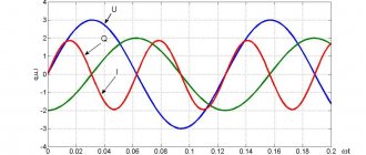
A very important factor is that this electrical quantity can be either positive or negative. It depends on what characteristics cos φ has. If the phase shift angle of a sinusoidal current is in the range from 0 to 90 degrees, then the active power is positive, if from 0 to -90, then it is negative. The rule is valid only for synchronous (sinusoidal) current (used to operate an asynchronous motor or machine tool equipment).
Also, one of the characteristic features of this characteristic is that in a three-phase circuit (for example, a transformer or generator), the active indicator is completely generated at the output.
Three-phase network calculation
Maximum and active power is denoted by P, reactive power by Q.
Due to the fact that reactive is determined by the movement and energy of the magnetic field, its formula (taking into account the phase shift angle) has the following form:
For non-sinusoidal current it is very difficult to select standard network parameters. To determine the required characteristics for the purpose of calculating active and reactive power, various measuring devices are used. This is a voltmeter, ammeter and others. Based on the load level, the desired formula is selected.
Due to the fact that the reactive and active characteristics are related to the total power, their relationship (balance) is as follows:
S = √P 2 + Q 2 , and all this equals U*I.
But if the current passes directly through the reactance. There are no losses in the network. This is determined by the inductive inductive component - C and resistance - L. These indicators are calculated using the formulas:
Inductance resistance: xL = ωL = 2πfL,
Capacitance resistance: xc = 1/(ωC) = 1/(2πfC).
To determine the ratio of active and reactive power, a special coefficient is used. This is a very important parameter by which you can determine what part of the energy is used for other purposes or is “lost” during operation of the device.
If there is an active reactive component in the network, the power factor must be calculated. This quantity has no units of measurement; it characterizes a specific current consumer if the electrical system contains reactive elements. Using this indicator, it becomes clear in which direction and how the energy shifts relative to the network voltage. To do this you will need a voltage triangle diagram:
Stress Triangle Diagram
For example, if there is a capacitor, the coefficient formula is as follows:
To obtain the most accurate results, it is recommended not to round the data obtained.