Time counters of the "DonKont" series are multifunctional devices that allow independent recording of two periods of time and the number of switching on of electrical equipment. Thus, this device can replace two conventional operating time counters and one pulse counter.
The counting of the first time period begins from the moment power is supplied to the device, and the second - according to the control signal from the additional sensor, which allows you to take into account the total operating time of the equipment and the useful work time.
DonKont SVN meters can be used as part of various industrial and household electrical equipment, such as electric motors, lifting mechanisms, autonomous power plants, refrigeration equipment, etc. A very economical solution is to use cathodic protection stations as part of them to take into account the total operating time of the station and the operating time in protection mode.
Non-volatile memory and an algorithm for guaranteed restoration of meter readings ensure uninterrupted time tracking, which allows timely planning and carrying out preventive and routine maintenance of equipment, thereby reducing possible costs for unplanned repairs of a particular unit, and indicators of useful work time and the number of on/offs allow analysis of operating efficiency and cyclical use of equipment. Due to the absence of mechanical parts, high reliability of the product is ensured.
This product has successfully passed tests on household gasoline and diesel generators as a device for recording engine hours, as well as as part of industrial equipment - cathodic corrosion protection stations, to record the total operating time, the time of protection of the structure and the number of equipment starts.
Brief technical characteristics of DonKont SVN meters:
| Range of total operating time taken into account, hour. | 0,0 — 99999,9 |
| Range of useful operating time taken into account, hour. | 0,0 — 99999,9 |
| Range of taken into account number of on/off switches, pcs. | 999999 |
| Number of control signal inputs from external sensors, pcs. | 1 |
| DC supply voltage, V* | from 4.0 to 26.0 |
| Maximum current consumption, A, no more | 0,025 |
| Operating temperature range, °C | from minus 60 to plus 60 |
| Overall dimensions, mm, (WxHxD): SVN "DonKont-1" SVN "DonKont-2" SVV "DonKont-3" | 60x60x20 50x50x15 50x50x50 |
| Meter weight, g: SVN "DonKont-1" SVN "DonKont-2" SVN "DonKont-3" | 53 33 115 |
| Service life, years | 10 |
* For the modification of the Doncont-3 SVN - 220 V AC power supply.
The meter is resistant to short-term temperature increases of 3 to 5 hours up to +70°C and to cyclic temperature changes from -60 to +60°C
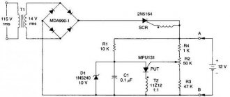
Schematic diagram
Figure 1 shows a diagram of a timer in which the duration of operation of the device and the duration of “rest” can be set separately from 90 seconds to 3 hours, separately for each mode.
The time intervals are set smoothly by two variable resistors. The values of time intervals depend on the parameters of RC circuits with variable resistors in the “R” components.
Therefore, this timer is suitable only in cases where very high precision in setting intervals is not required.
Rice. 1. Schematic diagram of a timer for periodically turning on and off the load.
The circuit consists of two timer nodes on CD4060 chips, switched using a trigger. One of these nodes “manages” the work period, and the other controls the “rest” period.
The CD4060 chip is a 14-bit binary counter with elements for a multivibrator. Therefore, CD4060 is often used in simple timer circuits.
On chip D1 there is a timer that runs during the operating period (on state) of the device. At the moment the power is turned on (or after pressing the S1 button), due to the charging of C2 through R8, the RS trigger on D3 is set to a state with a logical one at the output of D3.3. The transistor switch VT1-VT2 opens and turns on the device using relay K1.
At the same time, counter D1 starts working. And counter D2 is held at one from output D3.1 in the zero state. After some time, depending on the frequency of the built-in multivibrator (C1-R1-R2), a logical one appears at the senior output D1 (pin 3).
This unit switches the RS flip-flop D3 to the opposite state. The VT1-VT2 key closes and turns off the device. A unit from output D3.2 resets counter D1 and fixes it in this (zero) state.
Zero from output D3.1 allows counter D2 to operate. From this moment the countdown of the pause period (“rest”) begins. Now counter D1 is blocked, and counter D2 counts the pulses of its own multivibrator, the frequency of which, and therefore the time to reach the 8192 states, depends on the resistance R6.
After a specified time, a one appears at pin 3 of D2, and the circuit returns to its original state, that is, the electrical appliance turns on and starts counting D1.
Thus, thanks to the trigger on D3, the counters work alternately - D1 counts the duration of the on state of relay K1, then D2 counts the duration of the off state of K1, and so on.
Resistor R2 regulates the duration of the on state, and resistor R6 regulates the duration of the off state.
Buttons S1 and S2 are non-latching; they are used for manual control of the timer. By pressing S1, we switch the circuit to the load-on state, and by pressing S2, to the off-load state. In this case, the countdown of the corresponding time interval begins.
The HL1 LED signals that relay K1 is turned on.
The meters are produced in three modifications:
— SVN “DonKont-1” — Panel design. Unframed, with a metal panel hiding the board (color options are possible) for mounting on equipment control panels. The installation dimensions of this modification completely coincide with the installation dimensions of the common meters SVN-2-01 and SVN-2-02.
— SVN “DonKont-2” — Case version for installation in any places on the equipment. Overall dimensions 50x50x15 mm.
— SVN “DonKont-3” — Case version for installation in any locations on equipment powered by a single-phase AC 220 V mains. Overall dimensions 50x50x50 mm.
In all versions, the electronic elements and the meter board are coated with a specialized acrylic-based protective varnish for printed circuit boards PLASTIK Cramolin (Germany), which provides reliable protection from environmental influences.
Schemes for connecting the device to the electrical circuits of the equipment:
Operating mode 1 - three-pin switching circuit
Operating mode 2 - two-contact switching circuit. This operating mode uses only one total operating time counter and records the number of equipment starts.
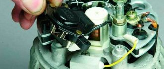
To connect the meter to the power supply circuits and external sensors, standard blade contacts (modification SVN "DonKont-1") or lead conductors (modifications SVN "DonKont-2" and SVN "DonKont-3" are used)
“SVN-DonKont” meters are microprocessor devices and can be programmed in accordance with the consumer’s technical specifications upon additional agreement.
Connection diagram for the DonKont-3 modification of the SVN
Intermittent timer
When leaving their homes, some apartment owners leave a machine at home, which turns on the lighting in the apartment for several hours every evening, creating the illusion that there is someone in the house. Although the machine can be used for other tasks that involve periodically turning on and off the network load.
A distinctive feature of the presented machine is a fairly large range of exposure times, which can be adjusted from a few minutes to several days by selecting the ratings of some parts. This was achieved thanks to the use of capacitor C2 with a double electrical layer of an ionistor in the timing circuit. The device has two independent regulators that set the duration of “Work” (R5) and “Pause” (R6).
The basis of the machine is a multivibrator on an operational amplifier (op-amp) DA1, which controls the operation of a short pulse generator made on a unijunction transistor VT1 - it, in turn, ensures the opening of triac VS1. The generator is powered from the mains through a rectifier using diodes VD5, VD6 with ballast capacitor C5. To power the multivibrator, a parametric stabilizer is installed, consisting of a ballast resistor R7 and zener diodes VD1, VD2.
The multivibrator is assembled according to a well-known circuit with a timing capacitor C2 and independent circuits for its charging (VD3, R1, R5) and discharging (VD4, R2, R6). The capacitor is not completely discharged and charged, but between two voltage values (approximately 5.2 and 4.2 V), determined by resistors R3 and R4 and the op-amp supply voltage. This is done in order not to exceed the operating voltage of the capacitor and to be able to implement short shutter speeds at low charging and discharging currents.
The multivibrator produces rectangular pulses; their duration and the pauses between them depend, as mentioned above, on the set resistances of the variable resistors. When the output of the op-amp is close to the supply voltage ("Operation" mode), the generator based on a unijunction transistor will begin to operate. Voltage pulses from it will be sent to the control electrode of the triac - it opens at the beginning of each half-cycle, and almost all the mains voltage is supplied to the load. The pulse repetition frequency significantly exceeds the network frequency, so the triac operates stably with a load in the form of a refrigerator motor.
Since for normal operation of a triac on alternating voltage, pulses of negative polarity must be applied to its control electrode, the switching circuit of a unijunction transistor is somewhat different from the traditional one - the control electrode of the triac is connected to the emitter circuit of the transistor.
When the output of the op-amp is close to zero (Pause mode), the generator will stop working and the triac will not open. The load will be de-energized.
For the element ratings and a specific instance of capacitor C2 indicated on the diagram, the duration of the “Operation” mode is determined by the formula: tp=0.1(R1+R5)C2, and the “Pause” mode - by the formula: tn = 0.1(R2+R6 )C2. The duration of each mode can be changed from two minutes to three hours.
When the machine is not working, capacitor C2 is naturally discharged, and immediately after turning on the timer it should charge to a voltage of approximately 5.2 V. This means that the duration of the first “Operation” cycle will be approximately R4/R3 times longer than that set by resistor R5. For a refrigerator, such a delay is even useful, since it will have time to gain the required cold. One more circumstance should be taken into account when the timer is first connected to the network - while the SZ capacitor is charging, the device may operate unstably. It is best to connect the load to the timer 10...20 s after it starts working.
In the machine you can use capacitor C2 - K58-9b, K58-9v; C1, NW - K52, K50-35; C4 - KM, KLS, K73; C5 - K73; variable resistors - SPO, SP4 with characteristic A (linear); permanent - MLT, S2-33. Unijunction transistor - KT117A-KT117G; diodes VD3, VD4 - KD104A, and VD5, VD6 - any rectifier with an allowable reverse voltage of at least 300 V. Triac - KU208V, KU208G; when the load power is up to 300 W, it is used without a radiator, and if it is higher (but not more than 1.1 kW), it must be installed on a radiator of the appropriate size.
To increase the duration of each cycle, it is necessary to reduce the charging and discharging currents, that is, increase the values of resistors R1, R2, R5, R6, and also increase the value of resistor R3 (this will increase the voltage to which capacitor C2 will be charged, but it should not exceed the operating ). In addition, an op-amp with lower input currents should be used. For example, in order to increase the maximum exposure time to one or several days, it is recommended to replace the KS147A zener diodes with KS133A, use K140UD12 as an op-amp, increase the values of resistors R5, R6 several times, and R3 - 10...20 times.
The printed circuit board is only in this form.