Home > Generators > Blocking generator: operating principle
Devices of this type are used to create signals with high duty cycle that are rarely repeated. They use a transformer, which is included in the feedback circuit. The presence of galvanic isolation at the output allows the formation of high-voltage pulses. This feature is used to power line scanning units and Tesla coils.
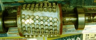
What does a blocking generator look like?
A simple generator blocking circuit can be assembled without difficulty at home.
Principle of operation
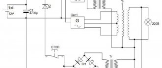
The diagram shown below will help you understand the functioning of the blocking generator.
Schematic diagram of a typical generator
The following list shows the main stages of work:
- After applying voltage through resistor R1, capacitor C is charged. The completion time of this process is determined by the parameters of these elements.
The amount of current is limited by the resistance of the circuit, and the voltage at the capacitor terminals does not have time to reach its maximum.
- As soon as it reaches a certain value, the transistor will begin to open. The current begins to flow through the circuit: transformer winding – collector – emitter. At this stage, the voltage reaches its maximum almost instantly and the current increases relatively slowly.
- It induces an EMF in the transformer winding connected to the base, which further increases the voltage and opens the transistor. This process ends when the transformer core is saturated (the material is not capable of conducting a magnetic field of a certain intensity). It will also stop when the base current increases, until the saturation threshold of the semiconductor device.
- The transistor turns off. Charging of capacitor C begins. The inductance of the transformer winding produces an emf in the direction opposite to the original one. This speeds up the closing of the transistor.
The principle of operation of a blocking generator is easier to understand with the help of timing diagrams, which illustrate the change in electrical parameters in individual parts of the circuit.
Current and voltage diagrams
These drawings must be studied in conjunction with the following drawing, which shows another circuit diagram of a blocking generator.
Generator blocking circuit
The figure above does not show a specific load (designation Rн). The diode performs damping functions. It prevents voltage surges that could damage the transistor.
The stages described above are clearly visible in the diagrams. Below are the features that are characteristic of the second scheme:
- The combination t0 marks the moment when the voltage at the base of the transistor is not enough to open it.
- The time interval t0 – t1 indicates the period of gradual opening of the transistor. At the end point, saturation has occurred, so changing the base current does not affect the pulse shape.
- However, the capacitor discharge occurs. Therefore, there is a gradual decrease in the base current.
- Since the load on the collector has inductive characteristics, the current Ic does not decrease. The duration of this period is determined by the parameters of the transformer core.
- The pulse cutoff begins at point t2. The current created by induction decreases, which provokes a gradual closing of the transistor switch. The figures show when current appears in the opposite direction. This process intensifies the discharge of the capacitor. The closing speed of the transistor increases, and the cutoff becomes steep (formed in a short time).
- Point t3 indicates the moment the transistor gate is completely closed. After it, the appearance of oscillatory processes is permissible. To block them, a diode is installed in this circuit.
TV Service
IP repair. Division into a blocking generator and a control circuit. The power supply based on discrete elements (transistors) is designed schematically in two parts: 1) a self-oscillator (blocking generator), 2) a device for controlling the operation of the self-generator (control circuit, KU switch and R limit). M50.jpg The autogenerator ensures the generation of pulse voltages at the TPI, and the device controls the output voltages of the power source and regulates the operation of the autogenerator when they change. The self-oscillator is usually made on: a) a powerful output transistor, b) a TPI winding operating in POS (Positive Feedback) mode, c) resistance Rst and capacitance Csv, connected in series between the POS winding and the base of the transistor d) bias resistance Rcm, switched on between Upit+ (rectified mains voltage) and the base of the transistor. e) a diode that ensures a constant unlocking current at the base of the transistor and shunts the RC circuit in the forward direction. The POS winding, Rst and Cst form a pulse of a certain shape based on the transistor. The diode forms a positive bias at the base of the transistor, thereby providing the necessary swing on the TPI windings. Rcm is used for the initial start of the autogenerator.
The idea of a repair technique. Disconnect the blocking generator from the control circuit and some of the loads on the secondary windings of the power supply, check its functionality, if necessary, repair it, and then connect the control circuit, loads, etc. in several stages. at the same time check the functionality and, if necessary, repair. But if you simply turn on the autogenerator, the power supply will immediately go into overdrive and the key transistor will fail. Also, if there are defects in the generator itself, the key transistor may also fail. Therefore, you need to check in two modes. All loads in the secondary power supply are switched off, with the exception of the diode and capacitance at B+, and a lamp of usually 220 volts 60 watts is connected in parallel to this capacitance. Then the control circuit and its power supply are turned off and a 220 volt 100 watt lamp is connected to the gap between the mains capacitor and the TPI winding. M50_2-2.jpg IP is turned on. Both lamps should light up and the IP should not make any extraneous sounds. If the lamp on B+ does not light up or the IP crackles, squeals, etc., then the blocking generator needs to be repaired. If normal, then the capacitor-TPI connection is restored and a 100-watt lamp is soldered in instead of the fuse. It is advisable to select lamps in such a way that the voltage at B+ is as close to optimal as possible. For the network, a set of lamps 200 watt, 150 watt, 100 watt, for the load 100 watt, 60 watt, 40 watt. If you don’t know which llamas are optimal for a given power supply, then it’s better to start with a 100-watt network and a 100-watt load. An increase in the power of the llama in the network circuit increases B+, an increase in power in the load decreases. After checking the functionality of the blocking generator in the second mode, the control circuit, loads, etc. are connected in series. At the same time, the functionality is checked and, if necessary, repaired.
For example, the repair method for IP chassis M50.
M50_PS.jpg Voltage at the working power supply: B+112 volts Q801 K 5.1v, E 9.7v, B 9.2v, Q802 K 0.0v, E 2.0v, B?, Q803 K 1.6v, E 0, 2c, B 0.4c.
The repair begins with checking the functionality of the generator. The following parts are unsoldered from one end: R831, R832, R831A, L804 (secondary IP) D805, D807, C810 (autogenerator control device). A 60-watt lamp is soldered parallel to C827 (B+) and between C806 and the 3rd leg of a 100-watt TPI.
M50_PS_2-2.jpg We connect the IP to the network. The IP must operate without any extraneous sounds (screaming, whistling, etc.). At B+ 64 volts. If there is no startup or extraneous sounds are produced by the TPI, then the blocking generator needs to be repaired. If normal, then the junction between the mains capacitor and TPI is restored and a 100-watt lamp is soldered in instead of the fuse. The operation of the blocking generator in this mode is checked. There should be 112 volts at B+ on the 82 volt mains capacitor. D805 and D807 are soldered back in. The following voltages should be Q801 K 10.0v, E 10.0v, B 9.4v, Q802, K 0.6v, E 3.1v, B 2.8v, Q803 K 3.3v, E 0.6v, B 0 ,6c. If there are large voltage deviations, we repair the control device. If normal, then solder back the C810, unsolder the lamp between the mains capacitor and the TPI and restore the connection at this point. After switching on, the voltage on B+ should be +112 volts. If necessary, adjust VR801. Then the lamp with B+ is unsoldered and R831, R832, R831A, L804 are soldered back. And the operation of the TV is checked and, if necessary, other units are repaired.
Thank you for your help in preparing the material viktor_ramb and Admin.
Calculation
Operating principle of a synchronous generator
The principle of operation of the blocking generator is clear. Below is a calculation that will help you choose the right transistor of the second circuit diagram.
For the example, the following initial parameters were used:
- frequency (F) – 40 kHz;
- duty cycle (C) – 0.25;
- amplitude (AM) – 6 V;
- resistance Rng (load) – 30 Ohm;
- voltage at the output of the power source (PS) – 300 V.
The permissible base-collector voltage should be from 1.5 to 2 times greater than NP. For this example - from 450 to 600 V.
The collector current ( Ik ) is determined by the formula:
Ik must be equal to or greater than ((3...5)*AM*CTF)/ Rng.
KTF is a coefficient that takes into account the features of energy transformation (collector - load windings):
CTF=(1.2*AM) / NP=(1.2*6)/300=0.024.
Thus, the permissible collector current must be greater than the following values:
((3…5)*6*0,024)/ 30 = 0,0144…0,024.
The maximum frequency (Chmax, kHz) is calculated using the following formula:
Hmax≥(5…8) * H = (5…8) * 40 = 200…320.
Based on the data obtained, the type of transistor is determined.
Parameters of a suitable conditional device:
- maximum collector-base voltage (NCV) – 620 V;
- maximum base-emitter voltage (NBE) – 8 V$
- maximum collector current (Ik) – 0.03 A;
- collector-base current (Ikb) – 12 µA;
- maximum frequency (Chmax) – 1000 kHz;
- base resistance (Rb) – 250 Ohm.
Calculation and practice allow you to assemble a blocking generator with your own hands
To create a blocking generator correctly, you need to know theory and practice, and be able to make calculations.
▍ How it all began
I first came across electroluminescent indicators (hereinafter referred to as ELI) back in childhood, when my uncle showed how it works by simply poking wires into a socket. But then I had neither knowledge nor skills, but the desire to deal with them remained. Then radiolok started posting a bunch of videos on his live channel about his experiments with these indicators. As a result, I got excited and bought several IEL-0-IX 131-27
. Control unit indicators, their performance is unknown, and how to check is also unclear. They require power supply ~220V 400Hz, and best of all 1200Hz 180V. The first thought is to try sticking it into a socket to check its functionality. When I did this, a breakdown of one segment immediately occurred before my eyes, because our outlet has a 230 V standard, and the amplitude value will be higher not by 10 V, but by 14! We'll figure out why this happens a little later. As a result, I was faced with the problem of creating my own regulated power supply for these devices.
Indication devices where high voltage is required.
In fact, not only ELs require high voltage, but also, for example, electronic light paper (aka EL paper), also requires high alternating voltage for its power supply, and in fact is also EL, only without a pattern. She's on the left in the photo. Neon lamps are also powered by high voltage, but if for a neon lamp it is not very important whether it is constant or alternating, then for the IN-12A gas-discharge indicator lamp, I still recommend using constant voltage. When alternating, capacitive effects begin, and the discharge “jumps” from digit to digit.
To summarize: it is necessary to make an alternating voltage source with an output frequency of 400 Hz and an effective voltage value of 220 V.
Field-effect transistor generator
The operating principle of this device does not differ from the options discussed above. But changes have been made to the scheme that significantly increase energy efficiency, reliability and durability.
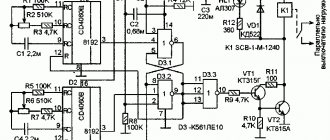
Field-effect transistor generator blocking circuit
Recommendations for proper assembly of the product:
- The domestic transistors and diodes indicated in the drawing can be replaced with similar imported semiconductor devices with suitable electrical characteristics.
- Resistance R2 is selected so that the voltage at C1 in idle mode does not exceed 450 V. This setting will prevent breakdown of the semiconductor junction of the VT transistor
- To avoid damaging the device, it should not be turned on without load.
- Resistance R6 performs protective functions. Its presence allows you to disconnect the generator from the network when the circuit breaker S is open
Electrolysis of water
In cases where we are talking about new types of electric generators, we should not forget about such a promising direction, which is the study of the electrolysis of liquids without the use of third-party sources. Interest in this topic is explained by the fact that water is inherently a natural, reversible source. This follows from the structure of its molecule, which, as is known, contains two hydrogen atoms and one oxygen atom.
AC generator
During the electrolysis of water mass, corresponding gases are formed, which are used as complete substitutes for traditional hydrocarbons. The fact is that when gaseous compounds interact, a water molecule is again obtained, plus a significant amount of heat is simultaneously released. The difficulty of this method is to ensure that the required amount of energy is supplied to the electrolysis bath, sufficient to maintain the decomposition reaction.
This can be achieved if you change the shape and location of the electrode contacts used, as well as the composition of the special catalyst with your own hands.
If the possibility of exposure to a magnetic field is taken into account, then it is possible to achieve a significant reduction in the power consumed for electrolysis.
Note! Several similar experiments have already been carried out, proving that, in principle, it is possible to decompose water into components (without additional pumping of energy).
All that’s left to do is master the mechanism that assembles atoms into a new structure (re-synthesizes a water molecule).
Another type of energy transformation is associated with nuclear reactions, which, for obvious reasons, cannot be carried out at home. In addition, they need enormous material and energy resources sufficient to initiate the process of nuclear decay.
These reactions are organized in special reactors and accelerators, where conditions with a high magnetic field gradient are created. The problem that specialists interested in cold nuclear fusion (CNF) face is finding ways to maintain nuclear reactions without additional input of third-party energies.
In conclusion, we note that the problem with the devices and systems discussed above is the presence of strong opposition from corporate forces, whose well-being is based on traditional hydrocarbons and atomic energy. CNF research, in particular, has been declared a wrong direction, as a result of which all centralized funding has been completely stopped. Today, the study of the principles of obtaining free energies is supported only by enthusiasts.
What it is
The term “free energy” itself appeared when internal combustion engines were widely introduced, when the problem of obtaining the required amounts of energy depended on the coal spent. Wood and petroleum products were also taken into account. Free energy is usually understood as a force that does not require spending a large amount of fuel to produce. This means that no resources are required. Including when they create a self-powered transgenerator.
Now they are creating fuel-free generators that implement similar schemes. Some of them began to work long ago, receiving energy from the sun and wind, and other similar natural phenomena. But there are other concepts aimed at circumventing the law on conservation of energy.
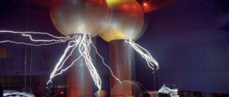
Tesla installation
How to get energy from the ether with your own hands?
Microquantum etheric flows in many such generators are the main sources from which energy for the generators comes. You can try connecting systems through capacitors and lithium batteries. You can choose different materials depending on the performance they provide. Then the number of kW will be different.
You might be interested in Milliamps to Amps
So far, free energy is a phenomenon little studied in practice. Therefore, many gaps remain in the design of generators. Only practical experiments help to find the answer to most questions. But many large manufacturers of electronic devices are already interested in this direction.
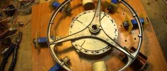
"Vega"
Not long ago, the Ukrainian company, which specialized in the production and sale of wind generators, began selling Vega fuel-free generators, which generated electricity with a capacity of 10 kW without any external source. Literally in a matter of days, the sale was prohibited due to the lack of licensing of this type of generators. Despite this, it is impossible to ban the very existence of alternative sources. Recently, more and more people have appeared who want to break out of the tenacious embrace of energy dependence.
The most famous ways to generate free power
The most popular are the works of Nikola Tesla. He was one of the first scientists to work on free energy generator circuits. He was involved in the development of wireless communications. It was based on flat coils with a magnetic field inside. As a result, the transformer has asymmetric mutual inductance. If you connect a load to the output circuit, this will not affect the power consumed by the primary winding.
During his work, Tesla began to pay attention to the transformer operating at resonance. Converted power into efficiency, which should have been more than one
To create such a circuit, I used single-wire designs. It was Tesla who created the term “free vibrations” and in his studies pointed to sinusoidal oscillations in an electrical circuit. Tesla's works are still famous today. Free energy has many followers.