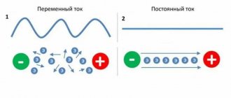
Methods of application
Current converters from 12 to 220 V are especially widely used in places where there is no electricity supply. Any car battery can be used to supply 220 V to supply electricity to a country house. It should be remembered that voltage inverters from 12 V to 220 V convert a form of electrical current that limits its use. That is, not all electrical devices are able to perceive voltage supplied graphically in an almost rectangular shape. Structurally, inverters are:
If we consider the output power, then car batteries produce a maximum of 500 W, and stationary ones - up to 10 thousand W. If, when leaving the city on vacation or at a summer cottage, it is necessary to illuminate a room or overnight stay in the evening, then the easiest way is to connect an LED lamp to the converter.
Energy consumption of a car battery is a very unprofitable process, since the efficiency of the battery decreases with increasing load.
Stationary voltage converters 12-220 volts are mainly used to transform electrical energy from solar panels and wind structures. Mobile inverter converters are connected to a network from 12 to 50 V and are considered unpretentious in choosing a power source. For car maintenance, this device is a charger with a socket.
Supply voltage
Gel battery from UPS
The input voltage of the autoinverter is usually from 10 to 15 volts. For trucks you need from 24 to 220. The thickness of the wires going from the battery to the inverter at 24V will be 2 times less, a small plus for heavy trucks. A car boost voltage converter must have protection against surges in the car's electrical network.
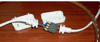
Example of thick cables
Pay special attention to the thickness of the wires running from the battery to the voltage converter. Small thickness may cause overheating. I usually think that the cross-section of the copper cable is equal to the number of Amperes. For example, if the cross-section is 1.5 mm 2, then the cable holds up to 15A. If the output power of a car inverter is 500W, then its total consumption from the battery will be 20% more.
- 500W * 1.2 = 600W
- 600W / 12V = 50A
At a maximum load on the inverter of 500W, the current through the cable from the car battery will be 50 Amperes. The cross-section of the copper cable required is 5mm 2. If it is less than required, the cable will heat up and the insulation will melt. The short circuit of the car battery is accompanied by a whole fireworks of sparks and special sound effects. It turns out like welding, the metal gets very hot and melts.
The on-board computer of some cars does not tolerate low supply voltage very well. This happened not very long ago with a relative in a Renault Koleos, the power went down and the on-board computer burned out, and the car became half-dead. The official dealer only offered to replace the entire unit at a cost of 100,000 rubles. I had to contact an electronics engineer, who re-soldered the microcircuit for 5,000 rubles and everything worked again.
Specifications
All electrical converters output a standard frequency of 50 Hz and a voltage of 220 V. This output meets the requirements of home electricity and is compatible with all consumers. The main parameters include:
- rated power;
- efficiency;
- active or passive cooling system;
- electricity consumption at idle;
- the value of the maximum current consumption at the input;
- supply voltage;
- protection devices against short circuits and overheating of equipment.
Old inverter designs are current transformers, while modern models are assembled on pulse controllers, ensuring high efficiency of the devices. Sometimes this value reaches 95%, and the remaining 5% is dissipated by the device itself, due to which it heats up.
Depending on the model of the 12-220 volt inverter, consumers receive a rectangular sine wave voltage at the output, or in more expensive designs it corresponds to the standard value. Some devices with high starting power cannot be started from a converter.
To do this, it is necessary to use adapters consisting of capacitors that can provide sufficient starting current. Sometimes it is simply necessary to limit the use of certain electrical equipment.
Schematic diagram
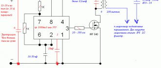
The proposed converter circuit (Fig. 1) operates at a frequency of 50 Hz and has overcurrent protection. In addition, this converter produces an output waveform that is closer to a sine wave, which reduces the level of high-frequency harmonics (interference).
Rice. 1. Circuit of a pulse converter on a 1114EU4, TL494CN or TL494LN microcircuit.
The device is assembled on a 1114EU4 microcircuit specially designed for switching power supplies (imported analogue of TL494CN or TL494LN). This allows you to reduce the number of parts used and make the circuit quite simple.
Inside the microcircuit there is a self-oscillator with a circuit for producing output pulses with pulse width modulation, as well as a number of additional components that provide its expanded capabilities. The output switches of the microcircuit are designed for a current of no more than 200 mA. To control more power, output pulses are sent to the base of key transistors VT1 and VT2.
Diode VD1 prevents damage to the circuit if the polarity of the power connection is incorrect (only the input fuse FU1 will blow).
Setting up the device begins with the transformer turned off by setting the frequency of the master generator to 100 Hz using the timing circuit R1C4. Since the microcircuit has a push-pull output, the output frequency is equal to half the frequency of the self-oscillator (50 Hz at outputs DA1/8 and DA1/11).
Resistor R7 adjusts the shape of the output pulses of the microcircuit in accordance with the diagram shown in Fig. 2. After this, the transformer is connected.
When the circuit supply voltage is from a 12-volt source, resistor R7 sets the rated voltage in the secondary circuit to 220 V (measure with a dial gauge). This is done with a connected load of 25...60 W.
Rice. 2. The shape of the output pulses of the 1114EU4, TL494CN or TL494LN microcircuit.
The R12C9 circuit may require selection of ratings in order to eliminate surges in the transformer along the fronts during transient processes during current switching.
Current protection of 10 A is set with resistor R10. This prevents damage to the converter in the event of an overload or short circuit on the output, since the circuit begins to reduce the output voltage, switching to current regulation mode.
The converter does not have feedback on the output voltage, since practical operating experience shows that it changes slightly when the power of the connected load changes and does not go beyond the permissible range of 190...240 V. The converter consumes no more than 1 A at idle, and with load - the current increases in proportion to the power.
Transistors are installed on a radiator with a surface area of at least 300 cm2. Transformer T1 is made independently. A magnetic core of the PLM27x40-73 type or similar was used. Windings 1 and 2 each contain 14 turns of PEL-2 wire with a diameter of 2 mm; winding 3 contains 700 turns of wire with a diameter of 0.5 mm.
Windings 1 and 2 must be symmetrical (this condition is easily met when they are wound simultaneously - with two wires at once).
The details used in the diagram are:
- capacitors C1, C2 type K52-1, C3-C8 - K10-17, C9 - K73-17V;
- fixed resistors R9 type C5-16MV, R12 - C5-5, the rest - MLT;
- trimmer R7-C5-2.
A 10 A fuse can be made from copper wire with a diameter of 0.25 mm. In the event of a converter overload, when the current limiting mode is triggered, a reduced supply voltage is not acceptable for all radio-electronic devices. In this case, current protection can be performed with automatic complete shutdown of the converter (Fig. 3).
Rice. 3. Current protection with automatic complete shutdown of the voltage converter.
For these purposes, it is convenient to use current relay K1, the group of contacts of which includes thyristor VS1. It is easy to make such a relay yourself using a reed switch. The current at which the contacts of the reed switch K1.1 close is adjusted by changing the number of turns of the winding (one layer is enough).
When the protection is triggered, the HL1 indicator lights up. To return the circuit to working condition, you will need to turn off the power to the converter for a while.
Useful properties of the devices
Often, inverters from 12 V to 220 V provide protection or weakening of the functioning of information systems from the quality of AC networks. If there is a sudden power outage, using a spare battery and rectifier will restore backup power and you can shut down your computer without losing essential data.
In complex and critical structures, these devices operate in a longer and more controlled mode. This work is carried out both separately and in parallel with the main electrical network. In addition, the inverter can work as an intermediate link in a converter complex.
A distinctive feature in this case is the presence of a high voltage frequency - up to 100 kHz. For efficient operation, semiconductor switches , magnetic materials and special controllers are additionally used. To be convenient for use, the inverter must have high efficiency, reliability and compact dimensions.
The output voltage must comply with the technical characteristics of the general network, especially for Grid-tie inverters, which are used to convert energy from solar panels, wind generators and other environmentally friendly sources.
Single-phase converters
They differ in the characteristics of the sinusoidal output voltage. More serious models are capable of producing a sinusoid close to the standard mains voltage. Another group of inverters produces a graph in a simplified form, which more closely resembles a trapezoidal shape.
The structure of the voltage sinusoid plays an important role for many household appliances.
Some of them do not operate on voltage supplied via a simplified sine wave. It is important for devices with:
- electric motors;
- transformers;
- telecommunication devices.
In addition, some medical equipment, audio and video equipment simply will not work if the output voltage is incorrect. Typically, inverters operate in three modes. During long-term operation, the rated power of the unit is used.
In short-term overload mode, energy consumption may be 1.5 times the rated power. During the starting mode, increased power is instantly released, which is used to start electric motors and other loads with increased capacity.
Criterias of choice
When selecting, you must consider:
- The current strength in the power circuit, which should not exceed 15 A in the case of switching to a socket in the car. When connecting an electrical device to a battery, the power is limited by the capabilities of the cable.
- List of devices that will be connected to the converter. For example, you may need a USB socket for the charging cable of a cell phone or tablet computer.
- Voltage stability. Some electrical appliances may operate unevenly when the voltage drops.
Additional protection
A modern inverter must have short circuit protection. It installs a safety device against accidental exposure to outside interference, especially when it comes to children.
Overload protection must be triggered in a timely manner to prevent overheating of the wiring and subsequent fire. The protection unit protects the converter from short circuits and high input voltage. For this purpose, there are indicators that show the state of the electrical network.
Additional sensors and installed voltmeters will help identify the corresponding malfunction. System temperature indicators located on the cooling radiator will allow you to control the fan when the readings exceed the permissible value.
Installation and connection rules
Basic requirements for proper installation and connection of the device:
- Before connecting to the battery or cigarette lighter, the converter switch should be switched to the “off” position.
- When installing equipment in the cabin or trunk, you must choose a dry and ventilated place ; do not allow hot air from the heating system or radiator to come into contact with the device.
- The housing should not be exposed to sunlight or come into contact with flammable materials.
- Before making connections, check the condition of the cigarette lighter housing and electrical wiring. Do not apply excessive loads or install oversized fuses.
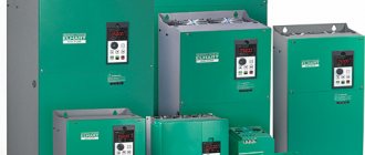
Popular models
A lot of inverter models are produced in our country. They can be used both in industrial production and in domestic conditions. The following are considered popular:
- AIRLINE API-150−01 - the permissible power threshold of the device is 150 W. The case is made of durable plastic that can withstand high temperatures. The car inverter is connected from the cigarette lighter, which is located in the passenger compartment. You can connect several electrical appliances to this device, the total power of which is no more than 150 W. The device is protected against short circuits and surges in incoming voltage.
- Jet A JA-P11 - if there is no electrical power network nearby, then this device will help out in any situation. The maximum power of the device is about 300 W. There is protection against low supply voltage, overheating and overload.
- Titan HW-150E1 150 W - makes it possible to use electrical appliances up to 150 W. It is connected from the car cigarette lighter and the output voltage is 220-240 V. The weight of the device does not exceed 0.5 kg, which makes it very convenient on long trips.
How does an autoinverter work?
In most cars, the voltage power is 12 W, and the auto-inverter converts this figure to 220v. Thanks to this conversion, the driver can connect any household appliances to the car’s power supply:
- Teapots.
- Microwaves.
- Drills.
- Pumps.
This is the most approximate list of possible connections, which can be significantly expanded. Car owners use a car inverter to connect various tools in the country, especially if there is no electricity there.
Another popular example of using the device is outdoor recreation. The auto-inverter guarantees a comfortable stay; you can take any equipment with you, including an electric barbecue grill.
In general, you can connect any devices designed for a voltage of 220v through it. When connecting more powerful or unstable devices, you should be vigilant, as the inverter may burn out. In order for a car inverter to produce the expected result during operation, its choice should be approached very carefully.
In what areas is a 12-220 V voltage inverter used?
With stable use of the battery, its charge level gradually decreases. The converter stabilizes the voltage if there is no electricity.
A 12-220 V inverter, made by yourself, will allow you to improve engineering structures in any room. The power value of devices that convert current is selected according to the total values of the operated loads. Power consumption processes can be reactive or active. Reactive loads do not fully consume the amount of energy received, causing the apparent power value to be greater than its active value.
Pure sine wave inverters are used when connecting an element whose total power is 3 kW. Significant fuel savings are ensured by the use of voltage converters and mini-power plants.
The following consumers are connected to the inverter design:
- alarm system;
- boiler;
- pumping apparatus;
- computer system.
Electrical voltage indicators
The inverter is capable of creating a modified sine wave. The voltage quality is sufficient to power household electrical appliances. Practice shows that this is one of the best options.
Most modern inverters also have a charger function. It is very comfortable. After all, the battery charge must be regularly replenished.
Naturally, the more additional options (charging, full protection, etc.), the more expensive the device will be.
Much attention must be paid to the choice of battery. Since most inverters are practically no different from each other (they are built on the same circuit). Unless they have different electrical equipment.
The choice of battery is based on the total power of all consumers in the room.
- Do you know how to properly weld using a welding inverter?
- Recommendations that will allow you to independently choose a welding machine - https://euroelectrica.ru/kak-vyibrat-svarochnyiy-apparat-dlya-doma/
The video will provide an overview of the classic current converter:
There are completely different situations when the owner needs to create a new voltage converter at home. The main purpose of this device is to provide a mains voltage value of 220 V from the original values of 12 W. The 12 to 220 inverter is made by hand by most amateurs, since a good quality inverter is quite expensive. Before assembling the device, you should understand the principle of its operation in order to have an idea of the mechanism of its operation.
Advantage of using voltage converters
Due to the fact that inverters have a number of positive characteristics, they are highly valued when used for various types of electrical equipment. The devices operate silently and do not pollute the environment with all kinds of emissions. The cost of servicing such devices is minimal: there is no need to check the pressure in the engine. Inverters have fairly insignificant mechanical wear, which allows them to be used by various consumers. Inverters 12-220 V operate at increased powers KR121 EU and have increased efficiency.
In the process of assembling inverters with master devices as multivibrators, the advantage of the converters is that the device is accessible and simple. The size of the products is compact, repairing them is not difficult, and they can be operated even at low temperatures.
Inverter with pure sine wave output
The circuits of daytime converters are complex even for experienced radio amateurs, so making them yourself is not at all easy. An example of the simplest circuit is below.
Inverter circuit 12 200 with pure sine output
In this case, it is easier to assemble such a converter from ready-made boards. How - watch the video. The next video shows how to assemble a 220 volt converter with pure sine wave. Only the input voltage is not 12 V, but 24 V. And this video explains how you can change the input voltage, but still get the required 220 V at the output.
Scheme and principle of operation of the inverter 12 220
The main part of radio components that use inverters use high frequencies in their operation. A pulse inverter completely replaces the classical circuit that uses transformers. The K561TM2 microcircuit is formed by two D-triggers, which have an R and S input. Such a microcircuit is created taking into account the use of CMOS technologies, by enclosing it in a plastic case.
The inverter master generators are mounted taking into account the K561TM2, using the DD1 device for operation. The DD1.2 trigger is mounted on the frequency divider. The amplification stages receive the signal from the microcircuits.
For operation, KT827 transistors are selected. If they are missing, then a transistor like KT819 GM or a field-effect semiconductor - IRFZ44 will do.
Generators with a sine wave for a 12-220 V inverter operate at high frequencies. To form a circuit with a size of 50 Hz, use a secondary winding with a parallel connection of capacitors and loads. By connecting any device, inverters create a conversion voltage of 220 V.
The circuit has one significant drawback - the imperfect form of the output parameters.
Speaking about how the 12 220 inverter works, it is worth pointing out that the K561TM2 chip is duplicated by the K564TM2. You can increase the power on the converter by selecting a more intense transistor. It is important to take into account the fact which capacitors are installed at the outputs. They have a voltage of 250 V.
Converter with the latest parts
A homemade inverter can operate in a stable mode if the transistor at the outputs operates from an amplified source with the main generator. For this purpose, it is allowed to use elements of the KT819GM series installed on dimensional radiators.
When creating converters, a simplified scheme is used. As the process progresses, you should take care of purchasing the necessary materials:
- microcircuits KR121EU1;
- transistors IRL2505;
- soldering iron;
- tin.
KR12116U1 microcircuits have a remarkable property: they contain a pair of channels for regulating the switch and allow you to quite simply make a simple voltage converter. Microcircuits in the temperature range from +25 to +30°C produce a maximum voltage value within the range of 3 and 9 V.
The frequency of the master oscillators is determined by the parameter of the element in the circuits. The IRL2505 transistor is installed when used on the outputs. It must receive a signal with the proper level, due to which the output transistor is adjusted.
The formed low levels do not allow the transistor to transition from closed modes to any other states. As a result, the occurrence of instantaneous current flows during simultaneous opening of the keys is completely eliminated. If high levels are observed to reach the first output, then this helps to turn off pulse generation. The circuit determines the connection of the common wire to pin 1.
To install push-pull cascades, T1 transformers and two transistors are used: VT1 and VT2. In open channels you can see a resistance value of 0.008 Ohm. It is insignificant, and therefore the power value of the transistor is small, even if a large current passes. Output transformers with a power of 100 W allow the IRL2505 to apply a current of 104 A, and pulse transformers are 360 A.
The main features of inverters include the ability to use any transformer that has two 12 V windings at its outputs.
If the output power is about 200 W, then in such cases the transistor is not installed on the radiator. It is important to consider that the value of electric current with a power of 400 W reaches about 40 A.
How does an inverter for fluorescent lamps work?
To make a converter that will illuminate a room of any size or car, it is enough to use a DIY assembly diagram. VOLTSL pulse converters are push-pull converters. They are mounted on power supplies TL 494 (KS 1114EU4). The microcircuits are controlled by the power parts of the power supply and consist of:
- voltage generator;
- voltage stabilizing source;
- two transistors on the output sources of electric current, the capacitance of which is 0.7 mm and 0.1 V.
To complete the installation, it is necessary to provide for the purchase of rectifier diodes and a transformer from the power supply. The issue of rewinding transformers should be addressed. When performing this work yourself, you should calculate up to 100 kHz. Each resistor is purchased, taking into account the circuit R1 and R2, creating the passage of a current pulse at the output. The operating frequency is formed when creating the circuit C1 and R3. HR307 diodes are mounted, but if they are not available, then use HER304. KD213 diodes have proven themselves quite well. The selection of capacitors is carried out with different capacities. Soldered chips are placed in panels. The circuits can operate for four hours - the design of the transistors does not overheat, and they do not need tuning.
Transformers are subject to independent winding. Therefore, it is necessary to stock up on ferrite rings with a diameter of 30 mm in advance. The basis uses a winding turns ratio of 1:120, while 1:1 is the primary winding and 20 is 200 turns with a secondary winding.
Initially, the secondary winding is wound using a wire with a cross-section of 0.4 mm. At the next stage, a primary coating is created, which consists of 2 halves of ten turns on each of them. Stranded soft wire with a diameter of 0.8 mm is used to create a half-winding. To remake the transformer, it is possible to use a device for a 12-volt lamp, which illuminates the ceiling. The secondary winding is removed, and the half-winding is created by winding the coverings when the wire is folded in half. After this, the connecting point is cut, and each end of the wires is soldered together, thereby forming the center of the winding.
For uninterrupted operation, it is necessary to use powerful metal conductors or field-effect transistors IRFL44N LRF46N. For converters, diodes HER307 and KD213 are installed. Computer power supplies with a diameter of 18 mm are used as capacitors.
During prolonged operation, the transistors heat up and radiators are not installed. If it is intended to be used, then the flanges on the transistor housing should not be wrapped through resistors. You should use a washer and spacer insulating materials from PC power supplies.
Inverters are reliably protected from overload if a fuse and diode are installed at the outputs. It is important that safety regulations are strictly followed: that is, high voltages must be avoided. Charges in capacitors can be stored for 24 hours. Discharge is carried out using 220 V incandescent lamps.
A 12V 220 inverter with your own hands can be made according to a simple diagram. Such a device is considered a fairly convenient device that allows you to receive a voltage of 220 V. Any devices made at home, in some situations, are absolutely in no way inferior to factory-made products, and in some cases even surpass them.
Video “Creating a converter for fluorescent lamps”
A voltage converter from 12 to 220 V is used where there is a need to connect electrical devices that consume standard mains current to an alternating voltage source. In many cases this network may not be available. The use of an autonomous gasoline generator requires compliance with the rules for its maintenance: constant monitoring of the level of working fuel, provision of ventilation. The use of converters in combination with car batteries allows you to solve the problem in an optimal way.
Precautionary measures
When working with automotive inverters, you must adhere to the following safety rules:
- Compliance with electrical safety measures.
- Do not use the inverter if the power cord is twisted, damaged, or disconnected, or if the housing is damaged.
- Do not use a faulty device to avoid causing a short circuit and fire.
- Do not expose the operating power converter to heat, flammable substances or direct sunlight.
- Protect the device from moisture, oily substances and high humidity.
Purpose and principle of operation
What is a voltage converter. This is the name given to an electronic device that changes the magnitude of the input signal. It can be used as a device to increase or decrease its value. The input voltage after conversion can change both its magnitude and frequency. Such devices that change DC voltage (convert it) into an AC output signal are called inverters.
Voltage converters are used both as a stand-alone device that supplies consumers with alternating current energy, and can be included in other products: uninterruptible power supply systems and supplies, devices for increasing direct voltage to the required value.
Inverters are harmonic voltage generators. Using a special control circuit, a DC source is created to periodically switch polarity. As a result, an alternating voltage signal is generated at the output contacts of the device to which the load is connected. Its magnitude (amplitude) and frequency are determined by the elements of the converter circuit.
The control device (controller) sets the source switching frequency and the shape of the output signal, and its amplitude is determined by the elements of the output stage of the circuit. They are designed for the maximum power consumed by the load on the AC circuit.
The controller is also used to regulate the magnitude of the output signal, which is achieved by controlling the duration of the pulses (increasing or decreasing their width). Information about changes in the value of the output signal at the load enters the controller via a feedback circuit, on the basis of which a control signal is generated in it to save the necessary parameters. This technique is called PWM (pulse width modulation) of signals.
In the circuits of power output switches of a 12V voltage converter, powerful composite bipolar transistors, semiconductor thyristors, and field-effect transistors can be used. Controller circuits are implemented on microcircuits, which are ready-to-use devices with the necessary functions (microcontrollers), specially designed for such converters.
The control circuit ensures the sequence of operation of the keys to provide at the inverter output the signal necessary for the normal operation of consumer devices. In addition, the control circuit must ensure the symmetry of the half-waves of the output voltage. This is especially important for circuits that use step-up pulse transformers at the output. For them, the appearance of a constant voltage component, which can appear when symmetry is broken, is unacceptable.
There are many options for constructing voltage inverter (IN) circuits, but there are 3 main ones:
- IN transformerless bridge;
- transformer IN with neutral wire;
- bridge circuit with transformer.
Each of them finds application in its own area, depending on the power source used in it and the required output power to power consumers. Each of them must have protection and alarm elements.
Review of the best autoinverters
The following parameters were used to compile the rating:
- power;
- output voltage quality;
- behavior under overloads;
- equipment;
- additional functions (if any);
- reviews in real life and on the Internet;
- appearance;
- average price in March 2016.
MAP "Energy" 900
Power 900 watts, input voltage 10-15 volts. Output voltage with a minimum number of harmonics and a frequency of 50 hertz. When the load exceeds 1.3 kilowatts, it automatically turns off. If the load is normal, then the voltage is stable. Can be used as a powerful starting charger (reverse conversion from 220 to 12 volts). Appearance - a large and heavy box with a digital indicator and switches. Cost 35 thousand rubles.
Calm PS12/300
Power 300 watts, input voltage 10.5–14 volts. Output voltage with a minimum number of harmonics and a frequency of 50-60 hertz. If the output load is less than 300 watts, then the voltage is stable. As the load power increases, the voltage begins to drop. The inverter is equipped with wires and connectors for connecting to a car battery, as well as an adapter for the cigarette lighter. It looks like a gray unsightly box with rubber legs. Cost 4500 rubles.
MobilEn SP-150
The declared power is 150 watts, but in tests it could withstand a load of 180 watts without reducing the voltage. Connecting an additional load triggers the protection. When overloaded, it signals with a slight but unpleasant squeak. After switching off it beeps very loudly. Output voltage with a minimum of harmonics with a frequency of 50-60 Hz. Equipped with a standard USB port, so you can use it to charge your phone, camera, video camera or iPod. Appearance - a small rectangular box, on one end of which there is a standard socket, on the other there is a double wire with an adapter for the cigarette lighter. Cost 1300 rubles.
MeanWell A301‑150‑F3
Power 150 watts, input voltage 10.5–15 volts. Output voltage with a minimum of harmonics and a frequency of 50-55 hertz. When the load increases to 175 watts, automatic shutdown occurs. Equipped with a standard socket and power cord with a cigarette lighter adapter. It looks like a neat silver cylinder. Cost 3500 rubles.
AcmePower DS-120
The declared power is 120 watts, but it works well only with a load of less than 100 watts. When the load power increases to 107-110 watts, the device automatically turns off. Output voltage with an average number of harmonics and a frequency of 50-60 hertz. Equipped with a standard USB port, so you can use it to charge your phone, camera, video camera or iPod. The kit includes a cable with an adapter for the cigarette lighter. Appearance – a neat small flat box made of black/gray plastic. Cost 750 rubles.
Types of converters from 12 to 220 volts
Simple converters from 12 to 220 are designed for low power consumers. The requirements for the quality of the output supply voltage and the signal shape are low. Their classic circuits do not use PWM microcontrollers. A multivibrator assembled on NAND logic elements generates electrical pulses with a repetition rate of 100 Hz. A D flip-flop is used to create an anti-phase signal. It divides the frequency of the master oscillator by 2. An antiphase signal in the form of rectangular pulses is formed at the direct and inverse outputs of the trigger.
This signal, through buffer elements on logic elements, does NOT control the output circuit of the converter, built on key transistors. Their power determines the output power of the inverters.
Transistors can be composite bipolar and field-effect. Halves of the primary winding of the transformer are included in the drain or collector circuits. Its secondary winding is designed for an output voltage of 220 V. Since the trigger divided the frequency of 100 Hz of the multivibrator by 2, the frequency of the output signal will be 50 Hz. This value is necessary to power the vast majority of household electrical and radio equipment.
All elements of the circuit are powered by the car's battery, using additional elements of stabilization and protection against high-frequency interference. The battery itself is protected from them.
The circuits of simple converters do not provide protection and automatic control elements. The frequency of the output signal is determined by the choice of the capacitance of the capacitor and the resistance of the resistor included in the master oscillator circuit. As the simplest protection against a short circuit in the load, a fuse is used in the circuit of the car battery supplying the circuit. Therefore, it is always necessary to have a spare set of fuse links.
More powerful modern DC-AC converters are made using different circuits. The PWM controller sets the operating mode. It also determines the amplitude and frequency of the output signal.
The 2000 W converter circuit (12 V+220 V+2000 W) uses a parallel connection of power active elements in its output stages to obtain the required output power. With this circuit design, the transistor currents are summed.
But a more reliable way to increase the power parameter is to combine several DC/DC (direct current/direct current) converters as the input signal of a common DC/AC (direct current/alternating current) inverter, the output of which is used to connect a powerful load. Each DC/DC converter consists of an inverter with a transformer output and a rectifier for this voltage. There is a constant voltage of about 300 V at the output terminals. All of them are connected in parallel at the output.
It is difficult to obtain more than 600 W of power from one inverter. The entire circuit of the device is powered by battery voltage.
Such circuits are provided with all types of protection, including thermal protection. Temperature sensors are mounted on the surface of the radiators of the output transistors. They produce voltage depending on the degree of heating. The threshold device compares it with the one specified at the design stage and issues a signal to stop the operation of the device with the corresponding alarm. Each type of protection is equipped with its own signaling device, often audible.
Additional forced cooling is also used using an air cooler installed in the case, which automatically comes into operation at the command of the corresponding thermal sensor. In addition, the case itself is a reliable heat sink, as it is made of corrugated metal.
According to the output voltage waveform
Single-phase voltage converters can be divided into two groups:
- with a pure sine wave output;
- with a modified sinusoid.
In the inverters of the first group, the high-frequency converter creates a constant voltage. Its value is close to the amplitude of the sinusoidal signal that is required to be obtained at the output of the device. In a bridge circuit, a component is separated from this constant voltage by pulse-width modulation of the controller and a low-frequency filter, its shape very close to a sinusoid. The output transistors open several times in each half-cycle for a time varying according to a harmonic law.
A pure sine wave is necessary for devices that have a transformer or electric motor at the input. The majority of modern devices can be powered by a voltage whose shape approximately resembles a sinusoid. Particularly low requirements are placed on products with switching power supplies.
Transformer devices
Voltage converters may contain transformers. In inverter circuits, they participate in the operation of master blocking oscillators that produce pulses that are close to rectangular in shape. This generator uses a pulse transformer. Its windings are turned on in such a way as to create positive feedback, leading to the creation of undamped oscillations.
The magnetic core (core) is made of an alloy with high magnetic field capacity. Thanks to this, the transformer operates in unsaturated mode. Various types of ferrites and permalloy have these properties.
Transformer blocking generators have been replaced by multivibrators. They use a modern element base and have higher frequency stability compared to their predecessors. In addition, in multivibrator circuits, changing the operating frequency of the generator is achieved in a simple way.
In modern inverter models, transformers operate in output stages. Through the output from the middle point of the primary winding, the supply voltage from the battery is supplied to the collectors or drains of the transistors used in them. The secondary windings are calculated using the transformation ratio for an alternating voltage of 220 V. This value is used to power most domestic consumers.
Design
The design of automotive current converters is lightweight, due to the use of semiconductors and electronic circuits for voltage conversion. As a rule, the case is made of aluminum, which solves the problem of heat dissipation. Powerful models are equipped with an active cooling system using a fan. Most inverters are protected against short circuits, overheating or overload, and are also equipped with a system that alerts you when the battery is critically low.
The device body contains the following elements:
- Power button.
- Power cord with cigarette lighter plug or battery terminals.
- Indicators and light bulbs.
- Operating mode switch.
- Hole for forced air circulation.
- Holes for fixing the device to the surface.
- Output sockets.