General information
When climbing a mountain, we do work against the force of gravity
Since we live in the era of electricity, many of us are familiar with the concept of electrical voltage from childhood:
After all, sometimes, while exploring the surrounding reality, we received a considerable shock from him by secretly sticking a couple of fingers into the power socket of electrical devices, secretly from our parents.
Since you are reading this article, nothing particularly terrible has happened to you - it is difficult to live in the era of electricity and not become briefly acquainted with it. With the concept of electric potential,
the situation is somewhat more complicated.
Being a mathematical abstraction, the electric potential is best described by analogy by the action of gravity - the mathematical formulas are absolutely similar, except that negative gravitational charges do not exist, since mass is always positive and at the same time electric charges can be both positive and negative; Electric charges can both attract and repel. As a result of the action of gravitational forces, bodies can only attract, but cannot repel. If we could deal with negative mass, we would master antigravity.
But you just have to push off...
The concept of electric potential plays an important role in describing phenomena related to electricity. Briefly, the concept of electric potential describes the interaction of charges of different or identical signs or groups of such charges.
From the school physics course and from everyday experience, we know that when climbing a mountain, we overcome the force of gravity of the Earth and, thereby, do work against the forces of attraction acting in the potential gravitational field. Since we have some mass, the Earth tries to reduce our potential - to pull us down, which we gladly allow it, rapidly skiing and snowboarding. Similarly, an electric potential field tries to bring like charges closer together and repel like charges.
It follows from this that every electrically charged body tries to lower its potential by getting as close as possible to a powerful source of an electric field of the opposite sign, if no forces prevent this. In the case of charges of the same sign, each electrically charged body tries to lower its potential by moving as far as possible from a powerful source of electric field of the same sign, if no forces prevent this. And if they interfere, then the potential does not change - while you are standing on level ground at the top of the mountain, the force of the Earth’s gravitational attraction is compensated by the reaction of the support and nothing pulls you down, only your weight presses on your skis. But you just have to push off...
Similarly, the field created by some charge acts on any charge, creating the potential for its mechanical movement towards itself or away from itself, depending on the sign of the charge of the interacting bodies.
"Sisyphus", Titian, Prado Museum, Madrid, Spain
Electric potential
A charge introduced into an electric field has a certain amount of energy, i.e., the ability to do work. To characterize the energy stored at each point of the electric field, a special concept was introduced - electric potential. The potential of the electric field at a given point is equal to the work that the forces of this field can do when moving a unit of positive charge from this point outside the field.
Returning to the analogy with the gravitational field, we can find that the concept of electric potential is akin to the concept of the level of various points on the earth's surface. That is, as we will consider below, the work of raising a body above sea level depends on how high we raise that body, and similarly, the work of moving one charge away from another depends on how far these charges are.
Let's imagine the hero of the ancient Greek world, Sisyphus. For his sins in earthly life, the gods sentenced Sisyphus to do hard, meaningless work in the afterlife, rolling a huge stone to the top of a mountain. Obviously, to lift a stone halfway up the mountain, Sisyphus needs to spend half as much work as to lift the stone to the top. Then the stone, by the will of the gods, rolled down the mountain, doing some work. Naturally, a stone raised to the top of a mountain of height H
(level H), when descending, will be able to do more work than a stone raised to level
H
/2. Sea level is generally considered to be the zero level, from which altitude is measured.
By analogy, the electrical potential of the earth's surface is considered zero potential, that is
ϕEarth = 0
where ϕEarth is the designation of the Earth’s electrical potential, which is a scalar quantity (ϕ is a letter of the Greek alphabet and is read as “phi”).
This quantity quantitatively characterizes the field’s ability to do work (W) to move some charge (q) from a given point in the field to another point:
ϕ = W/q
The SI unit of electrical potential is the volt (V).
Visitors to the Canadian Science and Technology Museum spin a large squirrel wheel, which spins a generator that powers a Tesla transformer (pictured right), which in turn creates a high voltage of several tens of thousands of volts, enough to puncture the air.
Voltage
One definition of electrical voltage describes it as the difference in electrical potential, which is given by the formula:
V = ϕ1 – ϕ2
The concept of voltage was introduced by the German physicist Georg Ohm
in a paper in 1827, which proposed a hydrodynamic model of electric current to explain Ohm’s empirical law discovered by him in 1826:
Tesla Transformer at the Canadian Science and Technology Museum
V = I R,
where V is the potential difference, I is the electric current, and R is the resistance.
Another definition of electric voltage is the ratio of the work done by the field to move a charge in a conductor to the magnitude of the charge.
For this definition, the mathematical expression for voltage is described by the formula:
V=A/q
Voltage, like electrical potential, is measured in volts
(V) and its decimal multiples and submultiples - microvolts (millionths of a volt, µV), millivolts (thousandths of a volt, mV), kilovolts (thousands of volts, kV) and megavolts (millions of volts, MV).
A voltage of 1 V is considered to be the voltage of an electric field that does 1 J of work to move a charge of 1 C. The dimension of voltage in the SI system is defined as
B = kg•m²/(A•s³)
Voltage can be created by various sources: biological objects, technical devices, and even processes occurring in the atmosphere.
Shark lateral line
The elementary cell of any biological object is a cell, which from the point of view of electricity is an electrochemical generator of low voltage. Some organs of living beings, such as the heart, which is a collection of cells, produce higher voltage. It is curious that the most advanced predators of our seas and oceans - sharks of various species - have a hypersensitive voltage sensor called the lateral line organ
, and allowing them to accurately detect their prey by heartbeat. Separately, it is perhaps worth mentioning electric stingrays and eels, which in the process of evolution have developed the ability to create voltages of over 1000 V to defeat prey and repel attacks on themselves!
Although people have been generating electricity, and thereby creating a potential difference (voltage), by rubbing a piece of amber on wool since ancient times, historically the first technical voltage generator was the galvanic cell
.
It was invented by the Italian scientist and doctor Luigi Galvani
, who discovered the phenomenon of potential difference arising when different types of metal and electrolyte come into contact.
This idea was further developed by another Italian physicist Alessandro Volta
.
Volta first placed plates of zinc and copper in acid to produce a continuous electric current, creating the world's first chemical current source. By connecting several of these sources in series, he created a chemical battery, the so-called “Volta Column
,” which made it possible to generate electricity using chemical reactions.
The Voltaic Pole is a replica made by an electrician at the Alessandro Volta Museum in Como, Italy. Canadian Science and Technology Museum in Ottawa
Due to his achievements in creating reliable electrochemical voltage sources, which played a significant role in further research into electrophysical and electrochemical phenomena, the unit of measurement of electrical voltage, the Volt, was named after Volt.
Among the creators of voltage generators, it is necessary to note the Dutch physicist Van der Graaff
, who created
a high-voltage generator
, which is based on the ancient idea of separation of charges using friction - remember amber!
The fathers of modern voltage generators were two remarkable American inventors - Thomas Edison
and
Nikola Tesla
. The latter was an employee at Edison's company, but the two geniuses of electrical engineering disagreed on methods of generating electrical energy. As a result of the subsequent patent war, all of humanity won - Edison's reversible machines found their niche in the form of generators and DC motors, numbering in the billions of devices - just look under the hood of your car or just press the power window button or turn on the blender; and the methods of creating alternating voltage in the form of alternating current generators, devices for converting it in the form of voltage transformers and transmission lines over long distances and countless devices for its application rightfully belong to Tesla. Their number is in no way inferior to the number of Edison’s devices - fans, refrigerators, air conditioners and vacuum cleaners, and a host of other useful devices, the description of which is beyond the scope of this article, operate on Tesla principles.
Housed at the Canadian Science and Technology Museum in Ottawa, this motor-generator, manufactured by Westinghouse in 1904, was used as a reliable power source to generate the exciter magnetic field at a hydroelectric power station in Niagara Falls, NY. NY. The construction of the power plant was led by Nikola Tesla and George Westinghouse
Of course, scientists later created other voltage generators based on other principles, including the use of nuclear decay energy. They are designed to serve as a source of electrical energy for space envoys of humanity into deep space.
But the most powerful source of electrical voltage on Earth, not counting individual scientific installations, is still natural atmospheric processes.
Every second, over 2 thousand thunderstorms rumble on Earth, that is, tens of thousands of natural Van der Graaff generators operate simultaneously, creating voltages of hundreds of kilovolts, discharging currents of tens of kiloamperes in the form of lightning. But, surprisingly, the power of terrestrial generators cannot be compared with the power of electrical storms that occur on the Earth’s sister - Venus - not to mention huge planets like Jupiter and Saturn.
Voltage characteristics
Voltage is characterized by its magnitude and shape. Regarding its behavior over time, a distinction is made between constant voltage (not changing over time), aperiodic voltage (changing over time) and alternating voltage (changing over time according to a certain law and, as a rule, repeating itself after a certain period of time). Sometimes, to achieve certain goals, the simultaneous presence of direct and alternating voltages is required. In this case, we talk about alternating current voltage with a constant component.
This voltmeter was used to measure voltage at the beginning of the 20th century. Canadian Science and Technology Museum in Ottawa
In electrical engineering, DC generators (dynamos) are used to create a relatively stable high-power voltage; in electronics, precision DC voltage sources are used on electronic components, which are called stabilizers
.
Reconstruction of the facility
In this case, the minimum possible amount of costs is considered, both for general construction work and for the energy component of the volume. You can consider many sub-items in assessing the economic efficiency of investments in an enterprise. But, it will also affect the reconstruction of the existing power supply systems of the facility. The choice of the final customer, represented by the chief power engineer or the chief engineer of the organization, should not be based on personal interests. The production capacities of competing organizations are not always qualitatively comparable. The price/quality ratio should always be checked by those interested in long-term operation. The optimally selected ratio allows the enterprise as a whole to temporarily forget about the issues of uninterrupted power supply with existing technologies in electrical engineering.
Voltage measurement
Voltage measurement plays an important role in fundamental physics and chemistry, applied electrical engineering and electrochemistry, electronics and medicine, and in many other branches of science and technology. It is perhaps difficult to find branches of human activity, excluding creative fields such as architecture, music or painting, where voltage measurements would not be used to control ongoing processes using various types of sensors, which are essentially converters of physical quantities into voltage. Although it is worth noting that in our time these types of human activities cannot do without electricity in general and without voltage in particular. Artists use tablets that measure the voltage of capacitive sensors when a stylus is moved over them. Composers play electronic instruments that measure the voltage on the key sensors and, depending on it, determine how hard a particular key is pressed. Architects use AutoCAD and tablets, which also measure voltage, which is converted into a numerical form and processed by a computer.
A kitchen thermometer (left) measures the temperature of meat by measuring the voltage across a resistive temperature sensor through which a small current is passed. In a multimeter (right), temperature is determined by measuring the voltage directly across the thermocouple
The measured voltage values can vary widely: from fractions of a microvolt in studies of biological processes, to hundreds of volts in household and industrial devices and appliances, and up to tens of millions of volts in ultra-powerful particle accelerators. Voltage measurement allows us to monitor the condition of individual organs of the human body by taking encephalograms
brain activity.
Electrocardiograms
and
echocardiograms
provide information about the condition of the heart muscle. Using various industrial sensors, we successfully, and most importantly, safely, control chemical production processes, which sometimes occur at extreme pressures and temperatures. And even nuclear processes at nuclear power plants can be controlled by measuring voltages. Using stress measurements, engineers monitor the condition of bridges, buildings and structures and even withstand such formidable natural forces as earthquakes.
A pulse oximeter, like a voltmeter, measures the voltage at the output of a device that amplifies the signal from a photodiode or phototransistor. However, unlike a voltmeter, here on the display we see not the voltage value in volts, but the percentage of hemoglobin saturation with oxygen (97%).
The brilliant idea of connecting different values of voltage levels with the state values of units of information gave impetus to the creation of modern digital devices and technologies. In computing, a low voltage level is interpreted as a logical zero (0), and a high voltage level is interpreted as a logical one (1).
In fact, all modern computing devices are, to one degree or another, voltage comparators (meters), converting their input states according to certain algorithms into output signals.
Among other things, accurate voltage measurements form the basis of many modern standards, the implementation of which guarantees their absolute compliance and thus safety of use.
The memory board used in personal computers contains tens of thousands of logic gates.
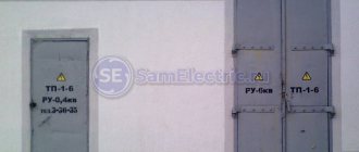
0.4 kV networks - carry energy to the main consumer
The most common electrical networks are considered to be 0.4 kV networks, since they penetrate our homes, cities and villages like a spider’s web. These networks are charged with the main task of supplying consumers with an accessible nominal electric current.
0.4 kV networks are a network made with a solidly grounded neutral, which allows them to be used both as single-phase and three-phase. This versatility allows them to be used everywhere in everyday life and on production sites. After all, in order to supply a household outlet with electricity, a phase and a zero (neutral), as well as a PE (protective) conductor are needed. And to supply a three-phase consumer, three phases are supplied from the switchgear, neutral N and PE - conductor.
The main problem with networks with a solidly grounded neutral is the voltage imbalance that occurs when there is an uneven load on single-phase consumers. And this problem cannot be dealt with by simply reversing the phases in the distribution panel, since the single-phase load is constantly changing, especially in everyday life. So it is simply physically impossible to coordinate voltage and current for single-phase consumers. And reversing the phases in the distribution board in order to achieve the rated voltage leads to an even greater spread of loads across the phases.
An alternative to this negative process should be the installation of stabilizers operating in a fairly wide voltage range. This will allow you to significantly save on the repair or replacement of equipment that can burn out from operation, both at low voltage and at high voltage.
Some people are quite often afraid of increased voltage, because they consider it the most dangerous; in fact, low voltage is much more dangerous. Since it is this that leads to overheating of the engines of refrigerators and washing machines. After all, the engine is designed for a certain load, and if it does not receive a sufficient voltage level, it draws more current, which causes it to overheat and burn out.
Modern electronics, where switching power supplies are used, make virtually no difference in the voltage level in the network. The most important thing is that it does not significantly exceed the permissible norms of 10% in our networks. So a computer, TV, radio and other similar devices are not affected by voltage drops.
The disadvantages of 0.4 kV networks include the fact that with the relative distance of consumers, quite large drops occur in power lines. This does not allow voltage to be stabilized even in three-phase networks, since consumers near the substation will have high voltage, while distant consumers will have low voltage. Moreover, with a consistent load, this factor will be observed in all phases.
Voltage measuring instruments
In the course of studying and understanding the surrounding world, methods and means of measuring voltage have evolved significantly from primitive organoleptic methods
- Russian scientist Petrov cut off part of the epithelium on the fingers to increase sensitivity to the action of electric current - to the simplest voltage indicators and modern devices of various designs based on the electrodynamic and electrical properties of various substances.
The taste of electricity. Once upon a time, a long time ago, if there was no voltmeter, we determined the voltage with our tongue!
By the way, novice radio amateurs easily distinguished a “working” 4.5 V flat battery from a “dead” one without any devices due to their complete absence, simply by licking its electrodes. The electrochemical processes that took place gave a feeling of a certain taste and a slight burning sensation. Some outstanding individuals undertook to determine the suitability of even 9 V batteries in this way, which required considerable endurance and courage!
An example of the simplest indicator - a mains voltage probe - can be an ordinary incandescent lamp with an operating voltage not lower than the mains voltage. There are simple voltage probes available on sale using neon lamps and LEDs that consume low currents. Be careful, using homemade structures can be dangerous to your life!
It should be noted that devices for measuring voltage (voltmeters) differ greatly from each other, primarily in the type of voltage being measured - these can be direct or alternating current devices. In general, in measurement practice, the behavior of the measured voltage is important - it can be a function of time and have a different form - be constant, harmonic, non-harmonic, pulsed, and so on, and its value is usually used to characterize the operating modes of electrical circuits and devices (low-current and power).
The following voltage values are distinguished:
- instant,
- amplitude,
- average,
- root mean square (rms).
The instantaneous voltage value Ui (see figure) is the voltage value at a certain point in time. It can be observed on the oscilloscope screen and determined for each moment in time using the oscillogram.
The amplitude (peak) voltage value Ua is the largest instantaneous voltage value over a period. Voltage swing Up-p is a value equal to the difference between the highest and lowest voltage values over a period.
The root mean square (rms) voltage value Urms is defined as the square root of the squared average of the instantaneous voltage values over the period.
All pointer and digital voltmeters are usually calibrated in rms voltage values.
The average value (constant component) of voltage is the arithmetic mean of all its instantaneous values during the measurement time.
The average rectified voltage is defined as the arithmetic mean of absolute instantaneous values over a period.
The difference between the maximum and minimum signal voltage values is called the signal swing.
Nowadays, both multifunctional digital instruments and oscilloscopes are mainly used to measure voltage - their screens display not only the voltage shape, but also the essential characteristics of the signal. These characteristics also include the frequency of change of periodic signals, therefore, in measurement technology, the frequency limit of the measurement of the device is important.
Newly built enterprises, factories, financed facilities, as well as joint ventures
Since new facilities and projects started from a “clean slate” are a “testing ground” for new technologies, the close attention of investors in these projects should also be focused on them!
In our opinion: the market for the supply of electrical equipment in the Russian Federation is clearly emerging.
— supplies of absolutely the entire spectrum of electrical products to the market of oil and gas, metallurgical and other large industries of our country. Without a doubt, at the moment, these are high-tech products that are developed in accordance with all existing regulatory documents in electrical engineering. It is also worth noting the quality of these products! If this concerns switchgears with a voltage of 0.4 kV, which we are talking about, these are switchboards with a sectional shape of up to 4V!, which is the worldwide limit for low voltage switchgears! At this stage of the development of the electrical market in Russia, only a few companies are working in this direction!
— the market, including “electrical control” at sites, supervised by foreign general contractors.
In this case, in many cases, the choice of the quality of the supplied equipment depends on the “intermediate” owners of the situation. Those. the customer of this or that object receives an end result that does not depend on his wishes. During the construction process there is a “struggle” for participation in the project, because in many cases of new construction, it is at least “indicative” on the scale of a city, region or part of our country! The struggle for volumes and for the “point” forces us to look for a compromise solution and, as a rule, it is not optimal according to the above ratio.
In the considered option, the main thing is to maintain a balance of the “price/quality” indicator. As a rule, organizations registered in the Russian Federation and which are subcontractors at a given facility strive for this ratio. They are also looking for reliable and proven partners to fulfill the stated volumes!
- that sector of the market in which numerous Russian enterprises exist.
There are so many possible markets for products here that it is simply impossible to list them. But the essence of movement and development is practically the same: the struggle is based on the “price/quality” evaluation criterion. The delivery time of the declared volume can also play an important role in leadership here.
I would like to address all of the above aspects primarily to the operating personnel of enterprises. These include directors and owners of production facilities, as well as hired personnel responsible for the uninterrupted operation of the technological process as a whole.
Since in our field, the main stakeholder is the personnel, primarily directly related to the energy sector of the enterprise, we provide some reference materials. We sincerely hope that they will be useful in the qualitative assessment of equipment put into operation at the facility!
Forms of sectioning of NKU 0.4 kV
- FORM 1: has no division;
- FORM 2A: provides separation of buses and functional units. The terminals for external conductors are not separated from the busbars.
- FORM 2B: provides separation of busbars and functional units from external conductor terminals.
- FORM 3A: Provides separation of functional units from each other and from buses, separation of external conductor terminals from functional units, but not from buses or from each other.
- FORM 3B: provides separation of functional units from each other and from buses, separation of terminals of external conductors from functional units and from buses, but not from each other.
- FORM 4A: provides separation of functional units from each other and from buses, the terminals of external conductors are in the same compartment with the functional units.
- FORM 4B: provides separation of functional units from each other, busbars and terminals of external conductors, which are also separated from each other and from busbars.
Measuring voltage with an oscilloscope
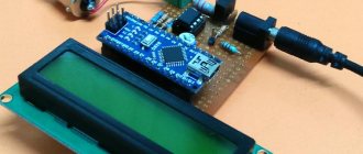
An illustration of the above will be a series of experiments on measuring voltages using a signal generator, a constant voltage source, an oscilloscope and a multifunctional digital instrument (multimeter).
Experiment No. 1
The general scheme of experiment No. 1 is presented below:
The signal generator is loaded onto a load resistance R1 of 1 kOhm, and the measuring ends of an oscilloscope and a multimeter are connected in parallel to the resistance. When conducting experiments, we take into account the fact that the operating frequency of the oscilloscope is significantly higher than the operating frequency of the multimeter.
Experience 1:
Let us apply a sinusoidal signal from the generator with a frequency of 60 hertz and an amplitude of 4 volts to the load resistance. On the oscilloscope screen we will observe the image shown below. Note that the cost of dividing the scale grid of the oscilloscope screen along the vertical axis is 2 V. The multimeter and oscilloscope will show an rms voltage value of 1.36 V.
Experience 2:
Let's double the signal from the generator, the scope of the image on the oscilloscope will double exactly and the multimeter will show double the voltage value:
Experience 3:
Let's increase the generator frequency by 100 times (6 kHz), and the frequency of the signal on the oscilloscope will change, but the peak-to-peak and root-mean-square value will remain the same, and the multimeter readings will become incorrect - the permissible operating frequency range of the multimeter is affected: 0-400 Hz:
Experience 4:
Let's return to the original frequency of 60 Hz and the voltage of the signal generator 4 V, but change the shape of its signal from sine to triangular. The scope of the image on the oscilloscope remained the same, but the multimeter readings decreased compared to the voltage value that it showed in experiment No. 1, since the effective signal voltage changed:
Experiment No. 2
The design of experiment No. 2 is similar to the design of experiment 1.
Using the knob for changing the bias voltage on the signal generator, we will add a bias of 1 V. On the signal generator, we will set a sinusoidal voltage with a swing of 4 V with a frequency of 60 Hz - as in experiment No. 1. The signal on the oscilloscope will rise by half a major division, and the multimeter will show an rms value of 1.33 V. The oscilloscope will show an image similar to the image from experiment 1 of experiment #1, but raised by half a major division. A multimeter will show almost the same voltage as it was in experiment 1 of experiment No. 1, since it has a closed input, and an oscilloscope with an open input will show an increased effective value of the sum of direct and alternating voltages, which is greater than the effective value of the voltage without a constant component:
Self-supporting insulated wires: reliability, quality and safety
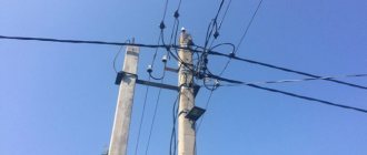
The task of maintaining the technical condition of networks at a modern level cannot be solved without the use of new, more advanced designs and technologies on overhead lines. Instead of traditional designs with bare wires, which have a high accident rate and low reliability, lines with insulated wires (SIP) have been adopted.
The basis of an overhead line with insulated wires (VLI) is made up of insulated phase wires twisted into a bundle around an insulated or non-insulated neutral carrier wire (SIP), while all mechanical impacts on the wires are perceived by the carrier wire.
Compared to bare wires, SIPs have great advantages:
- possibility of joint suspension on supports with telephone lines;
- the possibility of using supports of existing standard designs and supports of lower height (according to the PUE, suspension of self-supporting insulated wires is allowed at a height of 4 m, and for bare wires at a height of 6 m);
- reduction of operating costs by eliminating the systematic clearing of routes, replacing damaged insulators, and reducing the volume of emergency restoration work;
- high safety of service, no risk of electric shock when touching live wires;
- the practical impossibility of a short circuit between the phase wires and the neutral wire or to the ground;
- less weight and longer duration of snow adhesion, increased reliability in areas of intense ice formation, reduction of icy wind loads on supports by no less than 30%;
- reduced voltage drop due to low reactance (0.1 Ohm/km compared to 0.35 Ohm/km for bare wires);
- possibility of laying on building facades;
- eliminating the risk of fires if wires fall to the ground;
- reducing safe distances to buildings and other engineering structures;
- the possibility of joint suspension on one support of self-supporting insulated wires 0.4/10 kV and self-supporting insulated cable for voltage 10-35 kV;
- the use of these wires virtually eliminates theft of both electricity and the wires themselves.
Safety precautions when measuring voltage
Since, depending on the safety class of the room and its condition, even relatively low voltages of 12–36 V can pose a danger to life, the following rules must be followed:
- Do not carry out voltage measurements that require certain professional skills (over 1000 V).
- Do not measure voltages in hard-to-reach places or at heights.
- When measuring voltages in a household network, use special means of protection against electric shock (rubber gloves, mats, boots or boots).
- Use a proper measuring tool.
- In the case of using multifunctional instruments (multimeters), ensure that the parameter being measured and its value are correctly set before measurement.
- Use a measuring device with working probes.
- Strictly follow the manufacturer's recommendations for using the measuring device.
Literature
Author of the article: Sergey Akishkin
Calculation of losses
An important calculated value in 0.4 kV networks is the voltage drop along the cable length. Read the PUE on this topic:
- In Chapter 7, paragraphs 14 and 27 they say that you need to select the cross-sections of wires and cables in networks up to 10 kV according to the permissible parameters of the load current and voltage loss along the length. We do not confuse voltage loss along the length and voltage deviation in the network.
- We also read there that the permissible voltage losses along the length of the line from the transformer substation to the receiver should not exceed 10%.
It is reasonable to assume that from the substation to the ASU the loss along the length should not exceed 7.5%, from the ASU to the panel 2% and from the panel to the receivers another 2%. Total only 10%, according to the PUE.