Voltage transformers are devices designed to convert AC voltages in AC electrical circuits with a frequency of 50 or 60 Hz with rated voltages from 0.38 to 750 kV by means of electromagnetic induction. Reduction of high voltages in voltage transformers occurs without changing the frequency of alternating current. Voltage transformers are used to provide electricity to the current windings of relays and measuring instruments, such as ammeters, voltmeters, wattmeters and many others. The voltage transformer also protects devices connected to it from damage by high current if a short circuit occurs in the main circuit. Voltage transformers with two secondary windings, in addition to powering measuring instruments and relays, are intended to operate on earth fault signaling devices in a network with an isolated neutral or for protection against earth faults in a network with a grounded neutral. The use of voltage transformers in electrical installations makes it possible to isolate low-power, low-voltage measuring instruments and devices, which reduces the cost and allows the use of simpler equipment, and also ensures the safety of servicing electrical installations. Voltage transformers are used in such areas as electrical power engineering, electronics, and radio engineering. The transformer housing can be made, for example, from a compound based on a hydrophobic cycloaliphatic resin. This is necessary to protect the windings from environmental factors, as well as from mechanical damage.
Voltage transformers can be classified according to the following criteria:
- by the presence or absence of grounding of terminal X of the primary winding;
- by number of phases;
- by the number of windings;
- by the presence of a compensation winding or winding for monitoring network insulation;
- by type of insulation;
- by accuracy class;
- by cooling method;
- at the installation site;
- by rated voltage factor;
- by voltage class according to GOST 1516.3, kV;
- according to the highest operating voltage, kV;
- according to the rated voltage of the primary winding;
- according to the rated voltage of the secondary winding. If there are two secondary windings, then according to the rated voltage of the main secondary winding;
- according to the rated voltage of the additional secondary winding (if any);
- by rated power of the transformer, kVA (kilovolt-amperes);
- by maximum power of the transformer, kVA (kilovolt-amperes);
- by short circuit voltage;
- by the highest winding current;
- by working position in space;
- according to the degree of protection of the IP housing;
- according to climatic design;
- according to accommodation category according to GOST 15150;
- by operating temperature range;
- by overall dimensions;
- by weight, volume;
- depending on the model, brand, manufacturer.
Selection of current transformers
Current transformers are selected according to rated voltage, rated primary current and tested for electrodynamic and thermal resistance to short-circuit currents. A feature of the selection of current transformers is the selection according to the accuracy class and checking for the permissible load of the secondary circuit.
Accuracy classes of current transformers
- Current transformers for connecting meters for which cash payments are made must have an accuracy class 0,5.
- For technical accounting, it is allowed to use current transformers of accuracy class 1;
- To turn on indicating electrical measuring instruments - not lower than 3 ;
- For relay protection - class 10(P) .
To ensure that the current transformer error does not exceed the permissible value for a given accuracy class, the secondary load Z2 should not exceed the rated load Z2nom specified in the catalogs.
The inductive reactance of such circuits is small, so they take Z2p = r2p. The secondary load g2 consists of the resistance of the devices g prib, the connecting wires gpr and the contact resistance gk:
To determine the resistance of devices powered by current transformers, it is necessary to draw up a table - a list of electrical measuring instruments installed in a given connection.
The total resistance of devices, Ohm, is calculated based on the total power:
In 6-10 kV switchgear, transformers with /2nom = 5A are used; in switchgear 110 - 220 kV - 1 or 5 A. The resistance of the main contacts is 0.05 Ohm for two or three devices and 0.10 for more devices. The resistance of the wires is calculated by their cross-section and length. For aluminum wires, the minimum cross-section is 4 mm2; for copper - 2.5 mm2.
The estimated wire length depends on the connection diagram of the current transformer and the distance l from the transformer to the devices:
- when switching current transformers into an incomplete star;
- 21 - when all devices are turned on in one phase;
- l - when turning on current transformers in a full star.
In this case, the length l can be taken approximately for switchgear 6-10 kV:
- when installing devices in switchgear cabinets / = 4… 6 m;
- on the control panel /= 30…40 m;
- for RU 35 kV / = 45…60 m;
- for RU PO - 220 kV/ = 65...80 m.
If, with the accepted wire cross-section, the secondary resistance of the current transformer circuit turns out to be greater than ZHOU for a given accuracy class, then it is necessary to determine the required wire cross-section taking into account the permissible resistance of the secondary circuit:
where p is the resistivity.
The resulting cross-section is rounded up to a larger standard cross-section of control cables: 2.5; 4; 6; 10 mm2.
The conditions for selecting a current transformer are given in table. 7.5. Additionally, the following can be specified: KTN = 1t.tn/UR21nom - multiplicity of the dynamic resistance current of the current transformer; CT = /Т//|„ОМ – thermal resistance current multiplicity; /i„OM - rated current of the primary winding of the current transformer.
Based on the number of phases, voltage transformers can be divided into the following groups:
- single-phase;
- three-phase.
Both single-phase and three-phase voltage transformers are widely used in three-phase power supply. Three-phase voltage transformers are installed in a three-phase electrical network. Single-phase voltage transformers are also recommended to be installed in a three-phase electrical network in a group of one transformer for each individual phase. A group of three single-phase transformers installed on a common frame (platform) and electrically connected to each other according to a certain circuit is a three-phase group of single-phase transformers. Single-phase transformers have one core with a primary and secondary winding. In other words, only one phase at a time. Each three-phase transformer contains three rods (closed at the top and bottom) with a primary and secondary winding, which are then connected by one of two main circuits.
General structure and principle of operation
Each transformer is equipped with two or more windings inductively coupled to each other. They can be wire or tape, covered with an insulating layer. The windings are wound on a core, also known as a magnetic circuit, made of soft ferromagnetic materials. If there is one winding, such a device is called an autotransformer.
The operating principle of the transformer is quite simple and understandable. An alternating voltage is applied to the primary winding of the device, which leads to the flow of alternating current in it. This alternating current, in turn, causes the creation of an alternating magnetic flux in the magnetic circuit. Under its influence, an alternating electromotive force (EMF) is induced in the primary and secondary windings. When the secondary winding closes to the load, alternating current also begins to flow through it. This current in the secondary system differs in its own parameters. It has individual current and voltage indicators, number of phases, frequency and voltage waveform.
The design of the simplest power transformer includes a magnetic core made of ferromagnetic materials, mainly electrical steel sheets. The primary and secondary windings are located on the magnetic core rods. The primary winding is connected to the AC source, and the secondary winding is connected to the consumer.
According to the cooling method, voltage transformers can be divided into the following groups:
- oil-cooled transformers (or oil-cooled transformers);
- transformers with an air cooling system (dry and cast resin transformers).
Voltage transformers with natural air cooling (or “dry” transformers). This cooling system is carried out through natural air convection and partial radiation in the air. Conventionally, it is customary to designate natural cooling with an open design as C, with a protective design as SZ, with a sealed design as SG, with forced air circulation (blowing) as SD. Voltage transformers with natural oil cooling. This cooling system is designed for transformers with a power of up to 16,000 kVA. It is carried out by transferring the heat generated in the windings and magnetic circuit to the oil circulating through the tank and radiators, and then to the surrounding air. For better heat transfer to the environment, the transformer tank is equipped with fins, cooling pipes or radiators, depending on the power. Please note that the oil temperature in the upper, hottest layers should not exceed +95°C. Conventionally, it is customary to designate natural oil cooling as M. Oil-cooled voltage transformers with blowing and natural oil circulation. This cooling system is designed for transformers with a capacity from 16,000 kVA to 80,000 kVA. This is done by placing special fans in mounted radiator pipe coolers. The fan sucks in air from below and blows on the heated upper part of the pipes. The fans start and stop automatically depending on the load and oil heating temperature. Transformers with such cooling can operate with the blast completely turned off if the load does not exceed 100% of the rated load and the temperature of the upper oil layers does not exceed 55 °C, and also regardless of the load at negative ambient temperatures and the oil temperature does not exceed 45 °C. The maximum permissible oil temperature in the upper layers when the transformer is operating with a rated load of 95 °C. Conventionally, it is customary to designate oil cooling with blowing and natural oil circulation as D. Voltage transformers with oil cooling with blowing and forced circulation of oil through air coolers. This cooling system is designed for transformers with a power of 63,000 kVA and above. Coolers consist of thin finned tubes blown from the outside by a fan. Electric pumps built into the oil lines create continuous forced circulation of oil through the coolers. Thanks to the high oil circulation rate, large cooling surface and intense blast, the coolers have high heat transfer and are compact. This cooling system can significantly reduce the overall dimensions of transformers. Conventionally, it is customary to designate oil cooling with blast and forced circulation of oil through air coolers - DC. Oil-water-cooled voltage transformers with forced oil circulation. This cooling system is designed for powerful transformers from 160 MBA or more. It is performed in the same way as DC cooling (voltage transformers with oil cooling with blowing and forced circulation of oil through air coolers). The difference is that the coolers in this system consist of tubes through which water circulates, and oil moves between the tubes. The oil temperature at the inlet to the oil cooler should not exceed 70 °C. To prevent water from entering the transformer oil system, the oil pressure in the oil coolers in this case must exceed the pressure of the water circulating in them by at least 0.02 MP. Conventionally, it is customary to designate oil-water cooling with forced oil circulation - C.
Main characteristics
To protect critical electrical circuits from unexpected events, voltage stabilizers are used. Depending on the power, they are used in everyday life and in production. Nominal potential values for some objects are given in the table.
| Name of the construct | Character of current load | Unom in volts, unless otherwise noted |
| Cardiogram | Pulse | 1.0–2.0 mV |
| Battery: - little finger, alkaline cell | CONST | 1,5 |
| - Crohn's type | 9,0 | |
| TV antenna | High frequency | 1–100.0 mV |
| Laptop rectifier, car battery | CONST | 12,0 |
| Phone line | ―″― | 60 |
| Electric discharge: - ramp | ―″― | 250 |
| -eel | 650 | |
| Trolley system of tram, trolleybus | ―″― | 660 |
| Subway contact rail | ―″― | 825 |
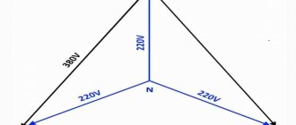
| Energy network: - Russian Federation | ~ variable | 220/380 |
| -U.S.A | 110/190 | |
| -Japan | 100/172 | |
| Electrified railway | ―″― | 25 kV |
| Same | Constant | 3 kV |
| thunder cloud | ―″― | ≥10 gigavolts (1 billion volts) |
Standard range of network nominal values ≥1000 V: 3.0; 6.0; 10.0; 20.0; 35.0... Significant excess of the standard is called overvoltage.
According to their operating position in space, voltage transformers can be divided into;
- devices with a vertical working position in space;
- devices with a horizontal working position in space;
- devices with any working position in space.
Rated voltage factor is the factor by which the rated primary voltage should be multiplied to find the maximum voltage at which the transformer meets the heating requirements for a specified time. The rated voltage of the windings of a voltage transformer is the voltage across the windings at no-load. The rated voltages of the primary windings of single-phase transformers connected between phases and three-phase transformers for voltages up to 1000 V must be 380 or 660 V.
The rated primary voltage of a transformer is the voltage that must be applied to its primary winding in order to obtain the secondary rated voltage specified in the transformer passport at the terminals of the open secondary winding. The rated secondary voltage of a transformer is the voltage that is established at the terminals of the secondary winding when the transformer is no-load (voltage is applied to the terminals of the primary winding, and the secondary winding is open) and when the rated primary voltage is applied to the primary winding. The rated power of the transformer, kVA (kilovolt-amperes) is the value of the total power indicated in the passport at which the transformer can be loaded continuously under rated installation conditions and cooling environment at rated frequency and voltage. The rated power of the voltage transformer can be: 10; 15; 25; thirty; 50; 75; 100; 150; 200; 300; 400; 500; 600; 800; 1000; 1200 VA. In the case when the transformer windings have different powers, the highest is taken as the rated one. The maximum power of voltage transformers can be: 160; 250; 400; 630; 1000; 1600; 2000; 2500 VA. The rated and maximum powers of three-winding transformers are taken to be the total powers of the main and additional secondary windings. Rated currents of voltage transformer windings are currents determined by their rated powers and rated voltages. Rated short circuit voltage Uk, % is the voltage as a percentage of the rated one, when applied to one of the transformer windings in a short-circuited other winding, the current is equal to the rated one. It characterizes the total resistance of the transformer windings. Housing protection degree (IP). The degree of protection of the housing from physical damage, precipitation, as well as its wear resistance and water resistance is indicated by IP (from the English Ingress Protection Rating - degree of protection of the shell). Numbers are indicated after the letters. The first of them indicates the degree of protection against solid fragments, the second - against the penetration of liquids. IP is a whole system for classifying the degree of protection of the enclosure of electrical equipment from the penetration of solid objects and water in accordance with the international standard IEC 60529 and GOST 14254-96. Let's list the main classes: IPХ0 (no protection), IPХ1 (protection against vertically falling drops of water), IPХ2 (protection against diagonally falling drops of water), IPХ3 (protection against small water splashes), IPХ4 (protection against large amounts of water splashes directed from all sides), IPХ5 (protection against strong jets of water directed from all directions), IPХ6 (protection even during temporary flooding), etc. Let us list the main classes of protection of lamp housings from the ingress of solid foreign bodies. IP0Х (no protection), IP1Х (protection from contact with a human hand and from solid foreign bodies with a diameter of more than 50 mm), IP2Х (protection from contact with fingers and from solid foreign bodies with a diameter of at least 12 mm), IP3Х (protection from damage by tools, wires and other similar foreign objects with a diameter of more than 2.5 mm), IP4X (protection from damage by tools, wires and other similar foreign objects with a diameter of more than 1.0 mm), IP5X (full protection from any external contact with foreign objects and protection from damage to equipment due to dust deposits inside the lamp body), IP6X (complete protection from any external contact with foreign objects, as well as protection from dust penetration), etc. A number of basic and most common degrees of protection of residual current devices: IP00, IP20, IP21, IP22, IP44. Models with a low degree of protection IP20, IP21 or IP22 are used in dry rooms. Such models have a low price. Models with a higher degree of protection, for example, IP44, can be used in rooms with high humidity. Such models are more expensive, but more reliable. Climatic design is a standard system of categories that includes the conditions of operation, transportation and storage of technical products relative to the macroclimatic zoning of the surface of the globe. In other words, this is a system of categories that determines under what conditions a particular electrical product can be operated, stored and transported. For instruments and technical products manufactured in the Russian Federation, GOST 15150-69 is applied. THE CLIMATE DESIGNATION ACCORDING TO GOST 15150-69 CONSISTS OF A LETTER PART AND A NUMERIC PART.
THE NUMERIC PART OF THE MARKING INDICATES THE PLACEMENT CATEGORY OF THE PRODUCT:
- open air;
- the same as 1 only without direct sunlight and without precipitation;
- indoors without climate control;
- indoors with ventilation and heating;
- in rooms with high humidity, without artificial regulation of climatic conditions.
Please note that the products may be used in macroclimatic areas other than those for which the products are intended, if the climatic factors during operation do not exceed the nominal values established for these products. For example, products of the UHL4 climatic version can be operated in UHL2 conditions during the dry summer period. Please note that products may also be designed for use in several macroclimatic regions; in these cases, combinations of various operating or storage conditions with periods of stay in these conditions are established in standards or technical specifications for products; climatic modifications (climatic modification category) must be indicated in the accompanying documents for the product. The warranty period for voltage transformers is usually up to 5 years. The service life of voltage transformers can be up to 30 years. Please note that in networks with an isolated neutral, voltage transformers may enter into ferroresonance with parasitic capacitances of distribution networks. This phenomenon is most often observed in cable networks. Voltage transformers in the presence of ferroresonant phenomena in the network fail. To prevent damage to voltage transformers as a result of ferroresonance, anti-resonance voltage transformers of the NAMI type have been developed.
ELECTROlaboratory
Good day, dear friends!
Today we will continue our conversation about instrument transformers. Let's talk about voltage transformers.
In the course of my work, I most often come across the following types of voltage transformers: STMI, which is now being replaced by NAMI and ZNOL.
Purpose of voltage transformers (VT
).
At voltages above 1000 V, direct switching on of devices is unacceptable both due to insulation conditions and the safety of operating personnel. In this regard, at high voltages, measuring instruments are switched on through intermediate instrument transformers, called voltage transformers (VTs).
VTs are designed both for measuring voltage, power, energy, and for powering automation, synchronization and relay protection of power lines from ground faults.
Designations of some voltage transformers most used in electrical installations.
NOM – TN. Single-phase, oil;
ZNOM – grounded HV input, voltage, single-phase, oil;
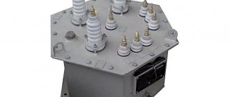
STMI – voltage, three-phase, oil, with a winding for monitoring network insulation;
Figure 1. Appearance of VT NTMI-6(10) kV.
Figure 2. Connection diagram of the windings of the TNMI-6(10) kV voltage transformer.
NAMI - voltage, anti-resonance, oil, with a winding for monitoring network insulation;
Figure 3. Appearance of TN NAMI-6(10) kV.
Figure 4. Connection diagram of TN NAMI-6(10) kV windings.
NKF - voltage, cascade, in a porcelain cover;
SR – series of voltage transformers: measuring, single-phase, capacitive with voltage 110-500 kV.
NOL.11-6.05; NOL.0.8; NOL.12; NOL – ungrounded voltage transformers 3-6-10 kV;
ZNOL.06; ZNOLE-35; ZNOL – grounded voltage transformers;
ZxZNOL; ZxZNOLP – three-phase anti-resonance groups TN;
Figure 5. Appearance of TN 3xZNOL-6(10) kV
Figure 6. Connection diagram of TN 3xZNOL-6(10) kV windings.
I would like to note that in high-voltage metering units installed on 10 kV overhead lines instead of resistors R1; R2; R3 (2.4 kOhm) one resistor R (0.8 kOhm) is installed. A frequently occurring defect is insulation burnout at the point of connection between the terminal X of the VT and resistor R1 (R2 or R3), which leads to a blown fuse in the phase in which the damaged resistor is located.
ZNOLP; NOLP – grounded and ungrounded transformer transformers with built-in protective safety devices. In transformers of these series, the high-voltage terminals of the primary winding are made with built-in protective safety devices (PSD), which, like the magnetic core with windings, are filled with an insulating compound, forming a monolithic block. The ZPU is made in the form of a collapsible structure with a fuse-link, which is a metal-dielectric resistor selected for each type of transformer. This device operates at currents less than 1 A, the shutdown time is from 5 to 10 seconds. After operation, the ZPU is subject to recharging, which is carried out by the personnel of the enterprise operating the transformer.
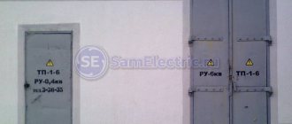
Figure 7. VT location in a high voltage cell.
What voltage is accepted in the secondary winding of the VT
.
For the main secondary winding of a VT with a rated voltage corresponding to the linear voltage of the network, the voltage is set to 100 V. Accordingly, for a VT with a phase rated voltage of the main secondary winding of 100 /V, when they are connected according to a star-star circuit, the secondary linear voltage corresponding to the rated one will also be 100 IN.
The rated voltage of the additional secondary windings is set in such a way that the maximum voltage value 3Uо (on an open delta) in the event of a single-phase ground fault in the network, when the line voltage corresponds to the rated voltage of the VT, is 100 V. Therefore, for additional VT windings intended for a grounded network neutral, set Unom = 100 V, and in a network with an isolated neutral Unom = 100/3 V.
Voltage transformers are manufactured with the following internal insulation design:
· Dry (voltage transformers up to 10 kV inclusive, type NOSK-6, ZNOLT-3, ZNOLT-6, ZNOLT-10, etc.).
· Oil-paper (transformers with voltage up to 35 kV inclusive, type NOM-10, NOM-35) with insulation of winding terminals at the full rated voltage.
· Cast epoxy (Czech single-phase voltage transformers and NOL type transformers).
TN tests.
Scope of voltage transformer testing:
1) measurement of the insulation resistance of the primary and secondary (secondary) windings (K, M)
2) high voltage testing of voltage transformers with cast insulation (K, M).
3) testing transformer oil (K, M). I would like to note right away that in transformer voltages up to 35 kV, transformer oil may not be tested
Note: K – major overhaul, testing upon acceptance into operation; M – overhaul tests
for voltage transformers 3-35kV
- when carrying out repair work in the cells where they are installed, if work is not carried out - at least once every 4 years.
The measured insulation resistance values during commissioning and operation must be no less than the values given in Table 5.
High voltage tests should be carried out in accordance with Table 6 or the requirements of the manufacturers.
That's all I have for today. If you have questions, ask, we will look for answers together.
Good luck!