When a short circuit occurs, the constant current values undergo significant changes. At the very first instant, the so-called aperiodic component of the short-circuit current appears, which quickly fades away and takes on a zero value. This time interval when these changes are observed represents a transition period, defined in numerical terms. Until the emergency current condition is turned off, the electrical network operates in a steady-state short circuit mode.
Physical properties of the aperiodic component
A similar current state occurs at the moment of a short circuit. Its duration and characteristics may vary, depending on many factors. For example, if the motor has a damper winding, the aperiodic component of the short circuit current will be lower than if it is absent. First, a supertransient current arises, which at first becomes simply transient, and only then does it begin to fade.
During a two-phase circuit, sudden changes in current do not appear in the stator. In such situations, at idle, an aperiodic component appears, the parameters of which coincide with the initial value of the variable component. Since the short-circuit current inside the stator is single-phase, in some cases the appearance of an aperiodic component is completely eliminated. In asynchronous motors, this indicator is not taken into account, since these processes die out very quickly. It is not taken into account even when calculating short-circuit surge currents.
In general, the magnitude of these components will differ for each phase. Its initial parameters will depend on the moment the short circuit appears. On the graphs it represents a solid curved line, since all the initial amplitudes of the other components will be equal to it, but directed in the opposite direction.
The presence of an aperiodic component is established when the contacts diverge. To evaluate it, there is a special parameter, which is the relationship between it and the periodic amplitude at the moment the contacts open. The decay time is approximately 0.1-0.2 s and is accompanied by significant heat generation. Under the influence of high temperatures, current-carrying parts and the entire equipment as a whole heat up noticeably, despite such a short period of time.
Total current when a short circuit occurs
The aperiodic component itself cannot be considered, since it is one of the components of the short circuit current. The electrical network contains inductive resistances that prevent the current from changing instantly at the moment a short circuit occurs. The increase in load current does not occur spasmodically, but according to certain laws that require a transition period from normal to emergency values. Calculation and analytical work is greatly simplified when the short-circuit current during a transition is considered as two components - aperiodic and periodic.
The aperiodic part is a component of the current ia with a constant value. It appears immediately at the moment of short circuit and in the shortest possible time drops to zero.
The periodic part of the short-circuit current Iпm is called the initial part, since in time it appears at the very beginning of the process. This indicator is used to select the most suitable setting or check the sensitivity of relay protection. This current is also known as subtransient current, since it is determined using subtransient resistances introduced into the equivalent circuit. The periodic current is considered to be steady when the aperiodic part fades and the transient process itself ends.
Consequently, the total short circuit current will be the sum of both parts - aperiodic and periodic during the entire period of state transition. At a certain moment, the total current reaches its maximum value in the shortest possible time. This condition is known as short-circuit shock current, which is determined when checking the electrodynamic stability of installations and equipment.
The choice of initial or supertransient current for calculations determines the rapid decay of the aperiodic part, which occurs before the protection is triggered. In this case, the periodic component remains unchanged.
Electrical networks connected to generator sets or a power-limited power system are characterized by significant voltage changes when a fault occurs. In this regard, the currents, initial and steady, will not be equal to each other. In order to calculate relay protection, you can use the initial current indicators. In this case, the error will be insignificant in comparison with the steady-state current exposed to various factors. First of all, this is increased resistance at the damaged point, load currents and other parameters that are most often not taken into account when performing calculations.
Calculation of three-phase short circuit
a) Current change during short circuit
Calculating a three-phase short circuit means determining the currents and voltages that occur during this type of damage both at the short circuit point and in individual branches of the circuit.
The current during a short circuit does not remain constant, but changes, as shown in Fig. 1-23. From this figure it is clear that the current, which increased at the first moment of time, decays to a certain value, and then, under the action of the automatic excitation regulator (AEC), reaches a steady value.
The period of time during which a change in the value of the short-circuit current occurs is called the transient process. After the change in the current value stops and until the short circuit is switched off, the established short circuit mode continues. Depending on whether relay protection settings are being selected or electrical equipment is being checked for thermal and dynamic stability, one may be interested in the current values at different times of the short circuit.
Since every network has certain inductive resistances that prevent an instantaneous change in the current when a short circuit occurs, its value does not change abruptly, but increases according to a certain law from normal to emergency value.
To simplify the calculation and analysis, the current passing during the short-circuit transient process is considered as consisting of two components: aperiodic and periodic.
ia , which has a constant sign, is called aperiodic.
, which occurs at the moment of a short circuit and decays relatively quickly to zero (Fig. 1-23).
Periodic component of short-circuit current. at the initial moment of time Inmo
called the initial short circuit current. The magnitude of the initial short-circuit current. used, as a rule, to select settings and check the sensitivity of relay protection. The initial short circuit current is also called subtransient, since to calculate it, the so-called subtransient generator resistance and subtransient e.m. are introduced into the equivalent circuit. d.s.
Steady-state short-circuit current represents a periodic current after the end of the transient process, caused by both the attenuation of the aperiodic component and the action of the ARV. Total short-circuit current represents the sum of the periodic and aperiodic components at any moment of the transition process. The maximum instantaneous value of the total current is called the short-circuit shock current. and is calculated when testing electrical equipment for dynamic stability.
As noted above, to select settings and check the sensitivity of relay protection, the initial or subtransient short-circuit current is usually used, the value of which is calculated most simply. Using the initial current when analyzing high-speed protections and protections with short time delays, the aperiodic component is neglected. The admissibility of this is obvious, since the aperiodic component in high-voltage networks decays very quickly, in a time of 0.05-0.2 s, which is usually less than the operating time of the protections in question.
With short circuit in a network powered by a powerful power system, the generators of which are equipped with ARVs that maintain a constant voltage on its buses, a periodic component of the current during the short circuit. does not change (Fig. 1-23, b). Therefore, the calculated value of the initial short-circuit current is in this case, it can be used to analyze the behavior of relay protection operating with any time delay.
In networks powered by a generator or system of a certain limited power, the voltage on the buses of which during short-circuiting. does not remain constant, but varies within significant limits, the initial and steady-state short-circuit current. are not equal (Fig. 1-23, a). At the same time, to calculate protections that have a time delay of the order of 1-2 s or more, it would be necessary to use the steady-state short-circuit current. However, since the calculation of steady-state short-circuit current relatively complex, it is permissible in most cases to use the initial short-circuit current. Such an assumption, as a rule, does not lead to a large error. This is explained as follows. For the magnitude of the steady-state short-circuit current. A significantly greater influence than the value of the initial current is exerted by an increase in the transition resistance at the site of damage, load currents and other factors that are not usually taken into account when calculating short-circuit currents. Therefore, the calculation of the steady-state short-circuit current. may have a very large error.
Taking into account everything said above, it can be considered appropriate and in most cases quite acceptable to use the initial short-circuit current for the analysis of relay protections operating with any time delay. In this case, a possible decrease in current during a short circuit should be taken into account for protections with a time delay by introducing increased reliability coefficients into the calculation compared to high-speed protections.
b) Determination of the initial short-circuit current. in a simple diagram
Since with a three-phase short circuit. (Fig. 1-24) e. d.s. and the resistances in all phases are equal, all three phases are in the same conditions. The vector diagram for such a short circuit, which, as is known, is called symmetrical, is shown in Fig. 1-18, b. The calculation of a symmetrical circuit can be significantly simplified. Indeed, since all three phases are under the same conditions, it is enough to carry out the calculation for one phase and then extend the results to the other two. The design diagram will have the form shown in Fig. 1-24, b. It is quite obvious that even in the simplest case under consideration, the last scheme is much simpler than that shown in Fig. 1-24, a.
In complex electrical circuits with many parallel and serial branches, the difference will be even more obvious.
So, in a symmetrical system, currents and voltages can be calculated only for one phase. The calculation begins with drawing up an equivalent circuit, in which individual elements of the design circuit are replaced with corresponding resistances, and for power supplies their e.m. is indicated. d.s. or terminal voltage. Each element is introduced into the equivalent circuit with its active and reactive resistance. The resistances of generators, transformers, and reactors are determined based on the passport data and are entered into the calculation as indicated below.
The reactance of power lines is calculated using special formulas or can be taken approximately using the following expression:
where l
— length of the line section, km;
hd
is the specific reactance of the line, Ohm/km, which can be taken equal to:
The active resistance of copper and aluminum wires can be calculated using the well-known expression
Allowed when calculating short-circuit currents. do not take into account the active resistance and introduce only the reactance of the elements into the equivalent circuit if the total reactance is more than 3 times the total active resistance
In the future, to simplify the reasoning, we will assume that condition (1-23), which, as a rule, is satisfied for networks with a voltage of 110 kV and higher, is valid, and we will only introduce the reactance of the design circuit into the calculations.
Determination of short-circuit current when powered by an unlimited power system. Short-circuit current in the design diagram (Fig. 1-25) will be determined according to the following expression, kA:
where xres
- the resulting resistance to the short-circuit point, equal in the case under consideration to the sum of the resistances of the transformer and the line, Ohm;
Uс
— phase-to-phase voltage on the buses of the unlimited power system, kV.
The definition of an unlimited power system means a powerful power source, the voltage on the busbars of which remains constant regardless of the location of the short circuit. on the external network. The resistance of an unlimited power system is assumed to be zero. Although in reality there cannot be a system of unlimited power, this concept is widely used in short circuit calculations. We can assume that the system under consideration has unlimited power in cases where its internal resistance is much less than the resistance of external elements connected between the system buses and the short-circuit point.
Example 1-1.
Determine the current. passing through a three-phase short circuit. behind a reactor with a resistance of 0.4 Ohm, which is connected to the generator voltage buses of 10.5 kV of a powerful power plant.
Solution.
Since the reactor resistance is much greater than the system resistance, it can be considered to be connected to unlimited power buses.
Then
Determination of short-circuit current when powered by a limited power system. If the resistance of the system supplying the short circuit point is relatively high, it must be taken into account when determining the short circuit current. In this case, additional resistance xspst
and it is assumed that behind this resistance there are buses of unlimited power.
Short-circuit current value is determined by the following expression (Fig. 1-26):
where xvn
- resistance of the short circuit between the busbars and the short circuit point;
xsist
- system resistance reduced to the source buses.
The system resistance can be determined if the three-phase short circuit current is specified. on its tires Ik.z.rear
.:
Example 1-2.
Determine the three-phase short circuit current. behind a resistance of 15 Ohms of a 110 kV line fed from the substation busbars. Three-phase short circuit current on the substation buses, reduced to a voltage of 115 kV, is equal to 8 kA.
Solution.
According to (1-26),
xsist
:
The current at the short circuit location is determined. in accordance with (1-25):
System resistance when calculating short circuit. can be set not by current, but by the short circuit power on the substation buses. Short circuit power is a conventional value equal to
where I k.z
.
— short circuit current; Ucp
is the average calculated voltage at the transformation stage where the short-circuit current is calculated.
Example 1-3.
Determine the three-phase short circuit current. behind the reactor with a resistance of 0.5 Ohm. The reactor is powered from the 6.3 kV busbars of the substation, short-circuit power. on which is equal to 300 MB • A.
Solution.
Let's determine the system resistance:
c) Determination of residual stress
In the diagram shown in Fig. 1-26, the amount of residual voltage on the busbars is determined according to the following expressions:
where x
k.z.
_ - resistance from the substation busbars, on which the residual voltage is determined, to the short-circuit location, or
X
- resistance from the power supply buses to the point at which the residual voltage is determined.
Since the resistance of the circuit under consideration is assumed to be purely reactive, expressions (1-27) and (1-28) include absolute values, not vectors.
Example 1-4.
Determine the residual phase-to-phase voltage on the substation buses in example 1-2.
Solution.
According to the first expression (1-27):
d) Calculation of short circuit currents and voltages in a branched network
In a complex branched network, in order to determine the current at the short-circuit location, it is necessary to first transform the equivalent circuit so that it has a simple form, if possible with one power source and one resistance branch. For this purpose, the series and parallel connected branches are added, the resistance triangle is converted into a star and vice versa.
Example 1-5.
Transform the equivalent circuit shown in Fig. 1-27, determine the resulting resistance and current at the short circuit. The resistance values are shown in Fig. 1-27.
Solution.
We transform the equivalent circuit in the following sequence.
To distribute the short-circuit current. along the branches of the circuit, you can use the formulas given in table. 1-1. The distribution of currents is carried out sequentially in the reverse order, starting from the last stage of equivalent circuit conversion.
Example 1-6.
Distribute the short-circuit current. along the branches of the diagram shown in Fig. 1-27.
Solution.
Let us determine the currents in parallel branches 4 and 7 in accordance with the formulas (Table 1-1):
Current I7
passes through resistance
x5
and then branches along parallel branches
x2
and
x3
:
The residual voltage at any point in a branched circuit can be determined by sequentially summing and subtracting the voltage drops in its branches.
Example 1-7.
Determine the residual voltage at points a and b of the circuit shown in Fig. 1-27. Solution.
If the equivalent circuit includes two or more e. etc., the points of their application are combined and they are replaced by one equivalent e. d.s. (Figure 1-28).
If e. d.s. sources are equal in magnitude, then the equivalent e. d.s. will have the same value
If e. d.s. not equal, equivalent to e. d.s. calculated using the following formula:
e) Calculation of short circuit currents according to the passport data of reactors and transformers
In all the examples discussed above, the resistance of individual circuit elements was specified in ohms. The resistances of reactors and transformers in passports and catalogs are not specified in ohms.
Reactor parameters are usually specified as a percentage as the relative value of the voltage drop in it when passing the rated current xP
, %.
The reactor resistance (Ohm) can be determined by the following expression:
where UHOM
and
IHOM
are the rated voltage and current of the reactor.
The transformer resistance is also specified as a percentage as the relative value of the voltage drop in its windings when passing a current equal to the rated current, uK
, %.
For a two-winding transformer, you can write the resistance (Ohms):
where uK
, %, and
UHOM
,
kV
, are indicated above, and
S HOM
is the rated power of the transformer, MB• A.
In the event of a short circuit behind a reactor or transformer connected to the buses of an unlimited power system, the current and power of the short circuit. are determined by the following expressions:
where IHOM
— rated current of the corresponding reactor or transformer.
Example 1-8.
Calculate the maximum possible current of a three-phase short circuit.
behind the RBA-6-600-4 reactor. The reactor has the following parameters: UH
= 6 kV,
IH
= 600 A,
xP
= 4%.
Solution.
Since it is necessary to determine the maximum possible short-circuit current, we assume that the reactor is connected to the buses of the system of unlimited power.
In accordance with (1-33) short-circuit current. behind the reactor will be determined as
Example 1-9.
Determine the maximum possible current and power of a three-phase short circuit.
behind the step-down transformer: SH
= 31.5MB • A,
UN1
= 115 kV,
UN2
= 6.3 kV,
uK
= 10.5%
Solution.
Assuming, as in the previous example, that the transformer is connected from the 115 kV side to the buses of the system of unlimited power, we determine the short-circuit current.
The rated current of the 6.3 kV transformer winding is:
How to calculate the aperiodic component
The initial value of the aperiodic part in modular terms is defined as the difference between the instantaneous indicator of the periodic part at the beginning of the short circuit and the current value immediately before the short circuit. That is, the aperiodic component with the maximum initial value will be equal to the amplitude parameters of the periodic part of the current when a short circuit occurs. This statement is determined by the formula: ia0 = √2Iп0, operating under the condition of a reduced active fraction of the resistance at the short-circuit point relative to the inductive component.
1. 2.
In addition, before the start of the circuit there should be no load at the design point, and the voltage of any phase by this time passes through the neutral conductor. If the listed requirements are not met, then the aperiodic part in the initial stage will reduce its performance in relation to the amplitude of the periodic component.
In order to calculate the aperiodic component of the short-circuit current at any arbitrary time, a substitution option is worked out in advance. According to the initial design scheme, all components are taken into account as active and inductive reactances. Accounting for synchronous generators and compensators, asynchronous and synchronous electric motors is carried out by transferring them to the category of inductive reactances with negative sequence. The resistance of the stator windings to direct current with the operating temperature of the established norm must be taken into account.
3.
When the initial calculation scheme contains only components connected in series, in this case the value of the aperiodic fraction at any time is determined by formula 1, in which Ta is a constant value that determines the decay time of this part. In turn, Ta can be calculated using formula 2, in which Xek and Rek will be the inductive and active components, and ωsync is the synchronous angular frequency of the mains voltage. If, in the calculations, it is necessary to take into account the value of the generator current immediately before the short circuit, then formula 3 is already used.
Calculation of short circuit current in a 0.4 kV network
To bookmarks
Introduction
In accordance with clause 3.1.8. PUE electrical networks must have protection against short-circuit currents, ensuring the shortest possible shutdown time; it is indicated that the protection must be checked in relation to the smallest rated short-circuit current (hereinafter referred to as the short-circuit current) to the rated current of the fuse link or circuit breaker release. (For more information about choosing protection against short-circuit currents, read the article: Calculation of the electrical network and selection of protection devices)
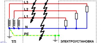
In 0.4 kV networks with a solidly grounded neutral, the smallest short-circuit current is the single-phase short circuit current, the calculation method of which is given in this article.
Basic concepts and calculation principle
The formula for calculating the short-circuit current itself is simple, it comes from Ohm’s law for a complete circuit and has the following form:
Iкз=Uф/Zф-о
Where:
- Uph - phase voltage of the network (230 Volts);
- Zph-o is the total resistance of the loop (circuit) phase-zero in Ohms.
What is a phase-zero loop (phase-zero)? This is an electrical circuit consisting of phase and neutral conductors, as well as the transformer windings to which they are connected.
In turn, the resistance of this electrical circuit is called the phase-zero loop resistance.
As you know, there are three types of resistance: active (R) , reactive (X) and total (Z) . To calculate the short circuit current, it is necessary to use the total resistance, which can be determined from the resistance triangle:
Note: The sum of the impedances of the neutral and phase conductors is called the impedance of the supply line.
It is quite difficult to calculate the exact resistance of the phase-zero loop, because its resistance is influenced by many different factors, starting with the transition resistance of contact connections and the resistance of the internal elements of protection devices, ending with the ambient temperature. Therefore, for practical calculations, simplified methods for calculating short-circuit currents are used, one of which is given below.
For reference: Short circuit current is determined by calculation, as a rule, only for new and reconstructed electrical installations at the stage of designing the electrical network and selecting its protection devices. In existing electrical installations, it is most advisable to determine the short-circuit current by carrying out appropriate measurements (by direct measurement of the short-circuit current, or by indirect measurement, i.e., measuring the resistance of the phase-to-zero loop and subsequent calculation of the short-circuit current).
Methodology for calculating short-circuit current
1) Determine the total resistance of the supply line up to the short circuit point:
Zl = √(R2l+X2l), Ohm
Where:
- Rl — Line resistance, Ohm;
- Xl — Line reactance, Ohm;
Note: The calculation is made for each section of the line with a different cross-section and/or conductor material, followed by the summation of the resistances of all sections (Zpl=Zl1+Zl2+…+Zln).
The active resistance of the line is determined by the formula:
Rl =Lfo*p/S, Ohm
Where:
- Lfo - Sum of the lengths of the phase and neutral conductors of the line, m;
- p - Specific resistance of the conductor (for aluminum - 0.028, for copper - 0.0175), Ohm* mm2/m;
- S - Conductor cross-section, mm2.
Note: the formula is given taking into account that the cross-sections and material of the phase and neutral conductors of the line are the same, otherwise the calculation must be performed using this formula for each of the conductors individually, followed by summing their resistances.
Line reactance is determined by the formula:
Chl =Lfo*0.6/1000, Ohm
2) Determine the resistance of the supply transformer
The resistance of a transformer depends on many factors such as the power, the design of the transformer and mainly the wiring diagram of its windings. For a simplified calculation, the transformer resistance for a single-phase short circuit (Ztr(1)) can be taken from the following table:
3) Calculate the short circuit current
The single-phase short circuit current is determined by the following formula:
Iкз=Uф/(Ztr(1)+Zpl), Ampere
Where:
- Uph - Phase voltage of the network in Volts (for 0.4 kV networks is taken equal to 230 Volts);
- Ztr(1 ) - Resistance of the supply transformer during a single-phase short circuit in Ohms (from the table above);
- Zpl - Total resistance of the supply line (phase-zero circuit) from the supply transformer to the short circuit point in Ohms.
Example of short-circuit current calculation
For example, take the following simplified single-line diagram:
- Determine the total resistance of the supply line to the point of short circuit
As can be seen from the diagram, there are three sections of the network in total; the resistance must be calculated for each separately, and then the calculated resistances of all sections must be added up.
- Section 1
Rl1 =Lfo*p/S=150*0.028/35=0.12 Ohm
Chl1 =Lfo*0.6/1000=150*0.6/1000=0.09 Ohm
Zl1 = √(R2l+X2l)=√(0.122+0.092)=0.15 Ohm
- Section 2
Rl2 =Lfo*p/S=20*0.028/16=0.035 Ohm
Chl2 =Lfo*0.6/1000=20*0.6/1000=0.012 Ohm
Zl2 = √(R2l+X2l)=√(0.0352+0.0122)=0.037 Ohm
- Section 3
Rl3 =Lfo*p/S=40*0.0175/2.5=0.28 Ohm
Chl3 =Lfo*0.6/1000=40*0.6/1000=0.024 Ohm
Zl3 = √(R2l+X2l)=√(0.282+0.0242)=0.281 Ohm
Thus, the total resistance of the supply line (phase-zero circuit) from the supply transformer to the short-circuit point will be:
Zpl=Zl1 +Zl2 +Zl3 =0.15+0.037+0.281=0.468 Ohm
- Determining the resistance of the transformer
As can be seen from the diagram, the power source is a 160 kVA transformer, with a “star-star” winding connection diagram with the neutral removed. We determine the resistance of the transformer according to the table above:
Ztr(1)=0.16 Ohm
- We calculate the short circuit current
Iкз=Uф/(Ztr(1)+Zpl)=230/(0.16+0.468)=366 Ampere
Was this article useful to you? Or maybe you still have questions ? Write in the comments!
Didn’t find an article on the website on a topic that interests you regarding electrical engineering? Write to us here. We will definitely answer you.
↑ Up
5
https://elektroshkola.ru/elektrotexnicheskie-raschety/raschet-toka-korotkogo-zamykaniya-v-seti-04-kv/