PTK Zapchastenergo LLC produces and sells various windings for oil-immersed power transformers. Windings are usually used as spare parts for the repair of oil power TMs.
The transformer winding is a set of turns that forms an electrical circuit in which an electromotive force is generated, induced in individual turns. The transformer winding contains a winding wire, insulating parts provided by the design; insulation creates the necessary channels for cooling, prevents their displacement under the influence of electromagnetic forces, and protects against electrical breakdown. Transformer windings differ in the number of turns, the type and direction of winding, the number of parallel wires in a turn, and the pattern of connecting individual parts of the winding to each other.
Aluminum and copper wire of rectangular and round sections in accordance with GOST 6324:52, GOST 9761:61 are used for windings of power transformers. Copper and aluminum transformer windings are used for transformers with a power of 20-1000 kVA. Copper, unlike aluminum, is endowed with higher thermal conductivity, greater elasticity, and increased mechanical strength. The tensile strength of copper wires is 3.5 times greater than that of aluminum wires, so it is not recommended to use aluminum windings in high-power transformers.
Since transformers vary in voltage, the windings will also differ. They may differ in the type of winding and its direction, the number of turns and parallel wires, as well as the connection diagram of individual parts into the whole system. To make the winding of an oil transformer, wires with enamel or cotton insulation are used. Power transformers use fiberglass wires, which are resistant to temperature changes.
Based on how the winding is located, the following types are distinguished:
- Concentric. They have a cylindrical shape and are located on a magnetic wire. In this case, the LV (low voltage) and HV (high voltage) windings are located opposite each other. As a rule, the LV winding is located closer to the wire.
- Alternating is the LV and HV winding of the transformer. They change places up the axis of the rod. When the voltage is high, it can be difficult to insulate the windings. That is why they most often resort to the first option.
Cylindrical winding of two layers
The winding principle in this case is the same as in the first option, only the wire is arranged in two layers. Both types should not exceed the number of 4 wires on one turn. This type is used for low voltage (LV). The power of a transformer with a two-layer winding should not exceed more than 550 kilowatts.
Transformer MV
Transformer MV
| Type | Transformers |
| Does gravity work? | No |
| Transparency | No |
| Luminosity | No |
| Explosion resistance | |
| Strength | |
| Tool | |
| Renewable | ? |
| Foldable | Yes (64) |
| Flammable | ? |
| First appearance | ? |
| Text ID | ? |
| Notes When destroying a block with a pickaxe, the main body of the machine falls out. | |
A medium voltage transformer
accepts up to 128 EE/t and delivers 512 EE/t from the “tee” (step-up mode), or up to 512 EE/t from the “tee” and delivers 128 EE/t from any other side (step-down mode).
Receipt
Craft
Recipe up to version 1.96 (game version 1.6.4 and lower). In IC2 Experimental this recipe is relevant again.
(In the game, another, “wrong craft” from one insulated copper wire is possible.)
| Ingredients | Process |
| Machine Main Body + Insulated Copper Wire |
Recipe from version 1.96:
| Ingredients | Process |
| Machine Main Body + Double Insulated Gold Wire |
Transformer winding made of aluminum wire (main sizes):
| Winding symbol | Transformer type | Side | Connection diagram | Voltage, kV | Overall dimensions, mm | ||
| Height | Inner diameter | Outer diameter | |||||
| B 4-25-10/0.4 | TM-25/10 | VN | Y/Y0-0 | 10 | 328 | 135 | 199 |
| VN 4-25-10/0.4 | 304 | 150 | 205 | ||||
| VN 4-40-10/0.4 | TM-40/10 | 392 | 160 | 230 | |||
| VN 4-40-10/0.4 | 344 | 160 | 241 | ||||
| VN 4-63-10/0.4 | TM-63/10 | 418 | 160 | 250 | |||
| VN 4-100-10/0.4 | TM-100/10 | 504 | 190 | 266 | |||
| VN 4-160-10/0.4 | TM-160/10 | 492 | 210 | 301 | |||
| VN 4-250-10/0.4 | TM-250/10 | 527 | 235 | 324 | |||
| VN 4-400-10/0.4 | TM-400/10 | 595 | 255 | 355 | |||
| VN 4-630-10/0.4 | TM-630/10 | 629 | 295 | 412 | |||
| NN 4-25-0.4/6-10 | TM-125/10 | NN | 0,4 | 328 | 90 | 127 | |
| NN 4-25-0.4/6-10 | 304 | 96 | 132 | ||||
| NN 4-40-0.4/6-10 | TM-40/10 | 392 | 107 | 146 | |||
| NN 4-40-0.4/6-10 | 344 | 106 | 144 | ||||
| NN 4-63-0.4/6-10 | TM-63/10 | 418 | 118 | 149 | |||
| NN 4-100-0.4/6-10 | TM-100/10 | 504 | 128 | 181 | |||
| NN 4-160-0.4/6-10 | TM-160/10 | 492 | 147 | 201 | |||
| NN 4-250-0.4/6-10 | TM-250/10 | 527 | 163 | 225 | |||
| NN 4-00-0.4/6-10 | TM-400/10 | 595 | 188 | 246 | |||
| NN 4-630-0.4/6-10 | TM-630/10 | 629 | 212 | 285 | |||
| VN 4-25-6/0.4 | TM-25/6 | VN | 6 | 328 | 135 | 199 | |
| VN 4-40-6/0.4 | TM-40/6 | 392 | 160 | 230 | |||
| VN 4-63-6/0.4 | TM-63/6 | 418 | 160 | 252 | |||
| VN 4-100-6/0.4 | TM-100/6 | 504 | 190 | 265 | |||
| VN 4-160-6/0.4 | TM-160/6 | 492 | 210 | 303 | |||
| VN 4-20-6/0.4 | TM-250/6 | 527 | 235 | 319 | |||
| VN 4-400-6/0.4 | TM-400/6 | 595 | 255 | 357 | |||
| VN 4-630-6/0.4 | TM-630/6 | 629 | 295 | 410 | |||
| VN 4-25-10/0.4 | TM-25/10 | VN | 10 | 290 | 145 | 208 | |
| VN S*-25-10/0.4 | 320 | 135 | 194 | ||||
| VN S-25-10/0.4 | 320 | 140 | 205 | ||||
| NN S-25-0.4/10 | NN | 0,4 | 290 | 95 | 135 | ||
| NN S*-25-0.4/10 | 320 | 91 | 124 | ||||
| NN S-25-0.4/10 | 320 | 90 | 130 | ||||
| VN S-40-6/0.4 | TM-40/6 | VN | 6 | 337 | 155 | 230 | |
| VN S-40-10/0.4 | TM-40/10 | 10 | 337 | 159 | 216 | ||
| NN S-40-0.4/6-10 | NN | 0,4 | 337 | 105 | 144 | ||
| VN S-100-10/0.4 | TM-100/10 | VN | 10 | 540 | 160 | 234 | |
| NN S-100-0.4/10 | NN | 0,4 | 540 | 115 | 148 | ||
| VN S-160-10/0.4 | TM-160/10 | VN | 10 | 530 | 203 | 280 | |
| NN S-160-0.4/10 | NN | 0,4 | 530 | 142 | 190 | ||
LV transformer
LV transformer
| Type | Transformers |
| Does gravity work? | No |
| Transparency | No |
| Luminosity | No |
| Explosion resistance | |
| Strength | |
| Tools | |
| Renewable | ? |
| Foldable | Yes (64) |
| Flammable | ? |
| First appearance | ? |
| Text ID | ? |
The low voltage transformer
accepts up to 32 EE/t and delivers 128 EE/t from the tee (step-up mode), or up to 128 UE/t from the tee and delivers 32 UE/t from any other side (step-down mode). If you check the voltage in the wire before and after the transformer, it will be the same 128 eE/t. The difference is that before the transformer there is one flow of 128 eE/t, and after 4x32 eE/t.
Receipt
Craft
| Ingredients | Process |
| Any boards + Coil + Insulated tin wire |
Old version:
| Ingredients | Process |
| Copper ingot + Insulated copper wire + Any boards |
Transformers with a capacity of 160–1600 kV A.
In Fig. 98, b shows the design diagram of the HV taps of a 630 kVA-A transformer with a rack switch. The assembly begins by installing a mock-up switch 2 on the upper yoke beams 8 (the switch itself is installed after drying the active part). Using bolts and nuts, fix the strips 5 and 6 and attach the adjusting bends 4. The bends are bent in place and placed in phases in the cutouts of the strip 5. In order not to damage the insulation, the bends of the taps (usually round 11V wires) are made with a radius equal to 6-10- multiple of the wire diameter. The ends of the taps are brought to the corresponding branches of the windings, measured in place and the excess length is cut off. The insulation is removed from the ends of the bends (by 40-50 mm) and the remaining part is secured, protecting them from unwinding. Bakelite paper tubes 12 are put on the ends of linear bends 3 from below and pre-clamped between strips 5 and 6. At the same time, bundles of adjusting bends of each phase are fixed. The lower ends of the X, Y and 1 HV windings are bent and brought to each other, assembling a “star” circuit. The windings are connected to the taps by electric soldering (windings made of copper) or argon-arc welding (windings made of aluminum). In both cases, before soldering (welding), wet asbestos is applied to the insulation of the ends, which protects it from damage. Finished connections are cleaned of sharp corners and solder residues and insulated according to the drawing; the adjusting bends are banded in phases with keeper tape 14. In places where they are fixed in the strips, the bends are insulated with strips of electrical cardboard 15-20 mm wide greater than the height of the strips. On the winding side, place a plate 13 made of electrical cardboard and finally secure the taps in the strips.
Main characteristics of the transformer
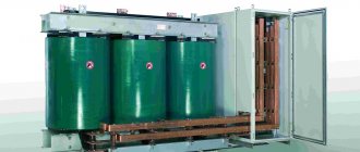
Figure 1.3 shows the appearance of the transformer TRDN-40000/110.
Figure 1.3 – Appearance of transformer TRDN-40000/110
In accordance with the accepted notation system, the abbreviation of the transformer TRDN-40000/110-U1 is deciphered as follows: T – three-phase transformer; P – presence of a split low voltage winding; D – cooling is carried out with natural circulation of oil and forced air circulation; N – voltage regulation is carried out under the load of the on-load tap-changer; 40000 – rated power of the transformer, kVA; 110 – voltage class of the high voltage winding, kV; U1 – climatic version, placement category according to GOST 15150. The main parameters of this transformer are given in Table 1.1 [].
Table 1.1 – Technical parameters of TRDN-40000/110-U1
| Rated frequency, Hz | 50 |
| Winding connection diagram and group | Υн/Δ-Δ-11-11 |
| Rated value of HV voltage, kV | 115 |
| Rated value of LV voltage, kV | 11 |
| Short-circuit voltage (HV-LV), % | 10,5 |
| No-load current, no more, % | 0,55 |
| On-load tap-changer control stages in the HV neutral | ±9x1.78% |
| Full service life, years | 25 |
The requirements for power transformers [, 6.4] say that to ensure long-term and reliable operation of transformers it is necessary to ensure:
- compliance with the required load, temperature conditions and voltage levels;
- compliance with the characteristics of transformer oil and insulation within the established standards;
- maintaining transformer cooling devices, oil protection, voltage regulation, etc. in good condition.
Transformer SVN
Transformer SVN
| Type | Transformers |
| Does gravity work? | No |
| Transparency | No |
| Luminosity | No |
| Explosion resistance | |
| Strength | |
| Tools | |
| Renewable | ? |
| Foldable | Yes (64) |
| Flammable | ? |
| First appearance | ? |
| Text ID | ? |
The ultra-high voltage transformer
accepts up to 2,048 EU/t and delivers 8,192 EU/t from the tee (step-up mode), or up to 8,192 EU/t from the tee and delivers 2,048 EU/t from any other side (step-down mode ).
Note: if the SVH transformer is switched to step-up mode and a current is passed through it, it will supply 8,192 EU/t, and the maximum voltage when receiving energy in energy storage devices is 512 EU/t (if you connect the transformer in any mode
to any energy storage device, then the energy storage will explode). PS In the experimental version, the maximum voltage when receiving energy in energy storage devices is 2,048 eE/t.
Receipt
Transformers with a capacity of 1600-6300 kVA.
There are many known design diagrams of transformers of the specified power; There are PBB and OLTC transformers with different locations of switches and voters, with different control schemes and the number of winding taps, etc., and this largely determines the features of tap assembly. For example in Fig. 99, and the installation diagram of the HV taps of the PBB transformer with a capacity of 1600 kVA is shown. PBB switches are usually mounted on the transformer cover, so when installing taps you have to use a mock-up of the switch or strictly follow the dimensions indicated in the drawing to its contacts. The assembly of the bends begins with the installation of 7-10 interconnected vertical and horizontal strips on the yoke beams. The wooden planks are connected to the spring beams and to each other with steel bolts 11 and nuts 13 (Fig. 99, c). There are basic and overhead planks. The main planks are connected to the beams; they create a supporting frame to which the overhead strips press the bends and fix their position on the active part. For reliable fastening, there are cutouts in the strips - oval, round or rectangular (Fig. 99, b).
Rice. 99. Installation diagram of HV taps of a PBB transformer with a power of 1600 kV-A: a - diagram, b - cutouts in the strips, c - fastening of the taps; 1 - strip, 2 - paper-bakelite tube, 3, 5 - compensators, 4 - PB wire outlet, 6 - PBV switch, 7-10 - strips, 11 - bolt, 12 - washer, 13 - nut, 14 - additional electrical cardboard insulation
The dimensions of the planks are chosen so that after tightening the bolts there remains a small gap between the planks. If the main and overhead strips are in contact, the overhead must be removed and additional insulation 14 must be wound onto the outlet. Bends from the PB wire are often passed into insulating tubes. If the outlet according to the drawing should have several bends (see Fig. 99, a), first put the tube on that part of it that occupies a horizontal position. Then the bend is bent and the remaining part is passed into another tube, bent again and finally the tube is put on the vertical part, fixed in a frame of wooden slats. The taps are installed so that the dimensions are maintained for connection to the transformer inputs or switch contacts. The reference point is one of the main strips or flanges of the yoke beam. In Fig. 99, and shows the distance (dimension K) from the beam to the linear input (all dimensions are indicated in the assembly drawing).
The ends of the winding wires and taps are bent, brought to each other, the excess length is cut off, the insulation is removed and soldered using electric soldering tongs. During soldering, the windings and insulation are covered with sheets of electrical cardboard, protecting them from drops and splashes of molten solder. The ends of the windings VN X, U and 1 are connected by the wire of the windings themselves. The wires of the last turn of the windings of phases A and C, cleared of paper insulation and varnish, are brought to the end U. The excess length of the ends is cut off, then they are fastened together and electrical soldering is performed. After stripping, all soldering areas are carefully insulated with paper or varnished cloth.
- Back
- Forward
Repair of transformers and low-voltage devices - Transformer windings
Page 17 of 38
WINDINGS OF POWER TRANSFORMERS The main element of the winding is a coil, that is, an electrical conductor, or a series of parallel-connected conductors, which covers part of the magnetic system of the transformer and in which an EMF is induced under the influence of the magnetic flux of this part. A winding is a set of turns that form an electrical circuit, where the EMF induced in the turns is summed up (in order to obtain the highest, average or lowest voltage of the transformer). In a three-phase transformer, a winding usually means a set of HV and LV windings of all three phases. Rice. 35. directions of winding windings: a - single-layer, b - multilayer and, c - disk spiral single coils, d - disk spiral pair coils The choice of winding design is made taking into account the power of the transformer per one rod, the metal of the winding conductor (copper or aluminum ), winding current - one rod, rated winding voltage and turn cross-section. The transformer windings consist of a winding wire and insulating parts provided by the design, designed to protect the winding bits from electrical breakdown and prevent their displacement under the influence of electromagnetic forces, as well as to create cooling channels necessary to remove heat from the windings of an operating transformer. Windings are distinguished by the direction of winding, location on the magnetic cores, the pattern of connecting individual winding elements to each other and the number of parallel wires. Based on the direction of winding, similar to the thread of a screw, right and left windings are distinguished. This applies to single-layer cylindrical screw windings (Fig. 35,a). The direction of a multilayer cylindrical winding is calculated according to the direction of winding of the first inner layer (Fig. 35.6). Individual coils, made in the form of a flat spiral, do not have a winding direction. Paired disk coils are considered right-handed if the wire from the upper outer end runs clockwise, and left-handed if the wire direction is counterclockwise (Fig. 35, c). The same definition also applies to continuous windings (Fig. 35, d). Most transformer windings are left-handed for ease of manufacture.
Rice. 36. Location of the HV and LV windings on the magnetic core: a - concentric, 6 - alternating; 1 - HV winding, 2 - insulating cylinder, - 3 - LV winding. Based on the location of the winding on the magnetic core, concentric and alternating windings are distinguished. Concentric is called an arrangement of windings when an LV winding mounted directly on the magnetic core is surrounded by a HV winding concentrically placed on this rod (Fig. 36, a). Only cylindrical windings are placed concentrically. Alternating windings are called LV and HV windings, placed on the magnetic core in the order of their alternation in the axial direction (Fig. 36, b). In accordance with GOST 11677 - 75, the beginnings and ends of the primary and secondary windings of power transformers are designated in a certain order. The beginnings of the windings of single-phase transformers are designated by the letters of the Latin alphabet A, a, and the ends - X, x. Large letters refer to the higher voltage windings, and small letters refer to the lower voltage windings. If in a transformer, in addition to the primary and secondary, there is also a third winding with an intermediate voltage, its beginning is designated At, and its end is designated Xt. In three-phase transformers, the beginnings and ends of the windings are designated: A, B, C; X, Y, Z - highest voltage; Lt, Vsh St, Xt, Ut, Zw - average voltage; a, b, c, x, y, z—lowest voltage. In three-phase transformers with phase connections in a star, in addition to the beginning of the windings, sometimes a zero point is also displayed, i.e., the common point of connection of the ends of all windings, designated O, From and o. Diagrams and groups of connections of the windings of three-phase two-winding transformers are shown in Fig. 37. A connection diagram in a star is usually denoted by the sign Y, and in a triangle - L. If the zero point of the windings is brought out, such a connection is indicated by the sign. It is allowed to write Y instead of Y, D instead of A and Un instead of Y in the text part of the technical documentation. If the transformer the higher voltage winding is connected in a star, and the lower voltage is connected in a triangle, this combination of windings is designated Y/D, with the zero point displayed - Y0/l (U/D or UN/D). The numerator of this “fraction” always includes the designation of the higher voltage winding, and the denominator - the lowest voltage. If there is a third winding connected, for example, also in a star, the designation of the third winding is placed between the designations of the high and low voltage windings (Y0/Y/A). The concepts of beginning and end of a winding are arbitrary, since when alternating current passes, any end of the winding can be called the beginning. However, when winding windings and especially when connecting them to each other, it is necessary to use these concepts. In the symbol in Fig. 37 numbers 12 or 0 and show the winding connection groups - zero and eleven. In the theory of alternating currents, electrical quantities (EMF, voltage, current) that sinusoidally change over time are usually depicted in diagrams as vectors. The vector is drawn as a line segment with an arrow. So, when depicting a voltage vector, the arrow indicates its direction; and the segment plotted on the scale is its value (at the moment of the greatest amplitude during the period). The angle of displacement of the linear voltage vector of the LV winding relative to the corresponding linear voltage vector of the HV winding, equal to 30°, is taken as the unit of the group. The displacement is counted from the linear voltage vector of the HV winding clockwise. So, for example, group 0 means that the linear voltage vectors of the LV windings are not shifted relative to the linear voltage vectors of the HV windings, i.e. they coincide; The 11th group corresponds to a displacement of linear voltages by 330° (11 multiplied by a unit of angular displacement of vectors equal to 30°). If the direction of the linear voltage vector of the HV winding is taken as the minute hand of the clock, and the direction of the linear voltage vector of the LV winding is taken as the hour hand, then group 0 (according to the old standard, the zero group was called the twelfth) will correspond to the coincidence of the hands - twelve o’clock. Receiving one or another group upon connection. windings in a circuit depend on the direction of their winding, the sequence of connection of the phase windings and the phase rotation when connected in a star or triangle. Great importance is attached to the direction of winding of the windings, since the direction of the EMF induced in the winding depends on this.
Rice. 37. The most common diagrams and groups of connections of the windings of three-phase two-winding transformers
For example, if two windings with the same winding direction are located on one rod, the directions of the EMF in the windings will coincide; if the winding directions are different, they will be opposite. Therefore, in order to avoid erroneous assembly and connections of transformer winding circuits, as mentioned earlier, dividing the windings into left and right is used. With the same circuits, different groups of winding connections can be formed. Possible groups of connections of the windings of three-phase transformers in a circuit widely used in transformers for general use, star-star with the neutral removed on the LV side (U/Vo) are shown in Fig. 38. The formation of one or another group of winding connections according to the V/Vo scheme can be traced using vector voltage diagrams, which conventionally show HV and LV windings with the same (left) winding directions of their turns (Fig. 38, a, b) and different ( Fig. 38, c).
Rice. 38. Possible groups of connection of the windings of three-phase transformers in a star-star circuit with the neutral removed: a - in the 0th group (same winding direction), b - in the 6th group (same winding direction, but the beginnings and ends of one of the windings remarked), in - in the 6th group (different winding directions) Some groups of connections of identically directed windings can also be obtained using the Y/D circuit. The designs and connection diagrams of transformer windings are varied, but in three-phase power transformers I - III of general purpose dimensions, predominantly cylindrical single-layer, double-layer, multi-layer, continuous and screw windings are used, connected according to a star-star circuit with the neutral brought out on the LV side. Below is a brief description of the design of these windings, which allows you to better understand the technology of repairing transformers with the manufacture of new windings. A single-layer cylindrical winding made of rectangular winding wire (Fig. 39, a) is simple in design and is used mainly in transformers with a power of up to 250 kV-A as an LV winding. It can be used at high power if it is subjected to special treatment during the manufacturing process to ensure its mechanical strength during short circuits. The winding layer consists of turns of one or more wires, wound along a helical line onto a paper-bakelite cylinder. Each turn in the layer is laid close to the previous one in the axial direction of the winding. The beginning and end of the winding are located at its opposite ends. A single-layer winding is also wound with a round winding wire.
Rice. 39. Cylindrical windings of power transformers: a - single-layer, b - two-layer, c - multilayer, d - continuous, e - screw; 1 - turns of rectangular wire, 2 - electric cardboard box to strengthen the outer turns of the winding, 3 - split leveling rings, 4 - paper-bakelite cylinder, 5 - end of the first layer of winding, 6 - vertical slats, 7 - internal branches of the winding, 8 - support insulating ring, 9 - end insulation, 10 and 11 - group and general transposition of winding turns
To give greater mechanical strength, a bandage of glass tape is applied to the winding, wound with a semi-overlap over the leveling rings and outer turns. Box 2 made of electrical cardboard with a thickness of 0.5 mm is attached to the outermost turn with one layer of cotton tape, applied in a semi-overlapping manner. The tape is glued after covering it with a thin layer of bakelite varnish. A two-layer cylindrical winding (Fig. 39.6) consists of turns wound in two layers with copper or aluminum wire of rectangular or round cross-section. The turns of each layer of the winding are laid in the same way as in a single-layer winding. They pass from layer to layer at the bottom of the winding. The beginning and end of the turns are brought out to the upper end of the winding. Between the layers of the winding there are vertical oil channels formed by vertically installed beech strips and strips of electrical cardboard and used to improve the cooling conditions of the winding due to the circulation of oil through these channels. To align the end part of the winding, split wedge-shaped rings made of electrical cardboard are installed at the ends of each layer. The two-layer winding is used mainly as the LV winding of power transformers with a power of up to 630 kVA, voltage up to 690 V. A multilayer cylindrical winding (Fig. 39, c) is wound, as a rule, from round wire. Winding is carried out by densely laying turns one to another with transitions from layer to layer. The first layer is wound on a paper-bakelite cylinder. Several layers of cable paper are laid between subsequent layers. To increase the cooling surface, an axial channel is created between some layers of the winding, formed by beech strips or slats made of glued electrical cardboard. To protect against mechanical damage and increase the level of insulation of the winding, a “side” is placed under the outer turns of each layer, which is a narrow strip of electrical cardboard up to 2 mm thick, glued to a wider strip of telephone paper. In the process of winding each layer of winding, the paper strip of the side is clamped by the outer turns, and a strip of cardboard serves as a support for the finished winding. Multilayer cylindrical windings made of round wire are used as high-voltage windings (less often LV) of oil transformers with a power of up to 630 kVA at a voltage of 35 kV and other transformers of higher voltage classes. A continuous winding (Fig. 39, d) consists of a number of coils wound continuously, that is, without breaking the wire when moving from one coil to another. In a continuous winding, half of the coils (usually odd ones) are transfer coils. The number of coils per rod ranges from 40 to 120; each coil consists of several turns wound flat, one turn on top of the other; the number of turns in the coil is from 2 to 40. The continuous winding coils of transformers of sizes I-III are wound on electric cardboard slats, laid on a paper-bakelite cylinder, which form a vertical channel along the inner surface of the winding. To create horizontal channels between the coils, electrical cardboard gaskets are attached to the slats. A continuous coil turn may consist of one or more parallel wires (usually no more than four). By using multiple parallel wires instead of a single large-gauge wire, eddy current losses in the winding are reduced. With two (or more) parallel wires in a coil, to equalize their length and resistance, as well as the position of each of them in the magnetic stray field when moving from coil to coil, transposition (rearrangement) of the wires is used, which is carried out during the winding process at each transition from coil to coil. reel. When performing a transposition, the relaying of each wire, as a rule, occupies one space between the spacers, so the number of spaces around the circumference of the winding occupied by transitions is equal to the number of parallel wires. Continuity of winding is achieved by rearranging the turns in the coils so that one junction is outside the winding, and the second is inside. The transition from coil to coil (internal and external) is carried out at the level of the outermost (internal or external) turn by bending the wire onto the edge. The number of coils of a continuous winding is most often even, with the beginning and end of the winding located either both outside or both inside the winding. Each coil can have a whole or fractional number of turns. Continuous windings are made with or without branches for voltage regulation. Regulating branches are removed from external (less often from internal) turns in such a way that the number of turns between adjacent branches corresponds to one control stage. Continuous windings of power transformers of sizes I and II are most often wound with APB aluminum wires, and more powerful ones with a voltage of 35 kV are wound with PB copper wire. The input coils of the 110 kV HV winding have partial capacitive protection (against overvoltages) in the form of capacitive rings and shielding turns. The capacitive ring is a washer pressed from electrical cardboard, wrapped in metal foil with breaks to prevent the formation of a short-circuited turn; The washer is insulated with several layers of cable paper. Shielding turns are made of wires with reinforced insulation and serve to equalize the electric field in the input coils. Due to their advantages, continuous windings are common in transformers of a wide range of powers and voltages. These include: a relatively simple design, high manufacturability, a large cooling surface and a large supporting surface, which makes the winding very resistant to axial forces arising from short circuits. A helical winding (Fig. 39d) consists of a number of turns wound with rectangular wires along a helical line, hence its name. Unlike a multilayer screw winding, it is single-layer with the wires arranged in the radial direction, one on top of the other in a spiral. Each turn of the winding consists of several identical parallel wires. Electric cardboard gaskets are installed between the turns of wires, forming oil channels to remove heat from the winding. A screw winding is also called multiparallel, since the total number of parallel conductors in the winding can reach several tens. Depending on the number of parallel wires and turns, the screw winding is single-pass or multi-pass, that is, it consists of one, two or more separate screw windings wound into one another during the manufacturing process. Since the parallel wires of a screw winding are located concentrically and therefore are at different distances from its axis, then, if they are not transposed, the windings located closer to the axis will be of smaller diameter and, therefore, shorter, and those more distant from the axis will be of larger diameter and longer. The difference in length and position in the magnetic stray field of parallel wires will cause inequality in their active and inductive resistances, and therefore, uneven distribution of current between them and increased heating of the lower cross-section of the turns of wires. Various types of transpositions are used in screw windings. In a single-pass winding, a combination of two types of transpositions is usually used: group, when parallel wires are divided into two groups and both are swapped, and general, when the relative position of all parallel wires changes. In addition, the Byud transposition is used, consisting of two group transpositions and one general one. A two-way helical winding uses a uniformly distributed transposition called Hobart transposition. With this type of transposition, the rearrangement of wires from one group to another is carried out at equal intervals along the entire length of the winding. The number of permutations in the winding is usually equal to the number of parallel wires. Schematic diagrams of wire transpositions in single-pass and double-pass windings are shown in Fig. 40, a, b.
Rice. 40. Schematic diagrams of the transposition of wires in screw windings: a - in a single-pass with group and general transposition of wires, b - in a two-pass with a uniformly distributed transposition of wires. The numbers indicate the numbers of the transposed wires. The screw winding has a significant end surface, high mechanical strength and a developed cooling surface. It is resistant to significant axial forces acting on the winding during short circuits. Screw winding is used in power transformers with a power of 1000 kV-A and above, mainly as LV windings. For the manufacture of windings of general-purpose power transformers, copper and aluminum winding wires of round and rectangular sections insulated are used: copper - with several layers of telephone or cable paper (PB); one layer of cotton yarn (PBO); two layers of cotton yarn (PBB); enamel and one layer of cotton yarn (PEBO); varnish-resistant enamel and one layer of cotton yarn (PELBO); several layers of telephone or cable paper and an open spiral of cotton yarn (PBBO); aluminum - several layers of telephone or cable paper (APB); two layers of cotton yarn (APBD); several layers of telephone or cable paper and an open spiral of cotton yarn (APBBO). If it is necessary to obtain a winding with a denser packing of turns, as well as to eliminate clogging of the oil with fluffs of cotton yarn, use winding wires of the PB and APB brands, insulated with two layers of paper.
- Back
- Forward
Equipment with a branch from the middle point of the secondary
The midpoint of the power transformer in this case is located between the windings. The output voltages are calculated from the upper and lower halves of the secondary - this is a mandatory condition. It is important to consider the number of turns located on the transformer. Depending on the quantity, the input voltage at the primary is determined. According to calculations, it will be V1/Va = T1/Ta V1/Vb = T1/Tb. In the formula, T1, Ta and Tb are the number of rings of the primary first half and the second half of the secondary windings, respectively. The required characteristics can be easily calculated using proportions. The values of Ta and Tb are identical, since they are the same in their own amplitude. The tap is selected from the secondary environment.
Separately, it is taken into account whether there is grounding of the middle point. If the answer is positive, the output voltages that arise on both halves of the transformer secondary will be in complete antiphase. If there is no grounding, then you will have to install additional loads or make one.