One of the electronic devices widely used in various circuits is the rectifier diode, with the help of which alternating current is converted into direct current. Its design is created in the form of a two-electrode device with one-way electrical conductivity. AC rectification occurs at metal-semiconductor and semiconductor-metal junctions. Exactly the same effect is achieved in electron-hole transitions of some crystals - germanium, silicon, selenium. These crystals are in many cases used as the main elements of devices.
Principle of operation
The operating principle of this device is based on the features of the pn junction. Near the junctions of two semiconductors there is a layer in which there are no charge carriers. This is the barrier layer. His resistance is great.
When a layer is exposed to a certain external alternating voltage, its thickness becomes smaller and subsequently disappears altogether. The current that increases is called forward current. It runs from the anode to the cathode. If the external alternating voltage has a different polarity, the blocking layer will be larger and the resistance will increase.
Areas of use
SS14 diode: characteristics
Valve-type rectifier elements in the field of electrical and electronic transformations are usually used for the following purposes:
- Switching (opening and closing operating circuits);
- Detection and limitation of signals of various shapes and durations;
- Direct rectification of alternating voltages, ensuring stable potential levels.
In addition, a classic rectifier diode made from silicon materials is the basis for creating so-called “bridge” circuits that include several elements at once (photo below).
Bridge circuit
With the advent of valve assemblies of four diodes connected according to the back-to-back principle, the rectifier modules themselves have been significantly simplified, while simultaneously facilitating their installation technology.
Due to such remarkable characteristics as low cost, simplicity of design and reliability in operation, rectifier diodes based on semiconductor junctions are widely used not only in electronic and electrical devices, but also in such a distant field as radio engineering.
Additional Information. In radio devices, these elements are used in high-frequency modes, providing rectification, switching and limiting of received over-the-air signals.
In the final part of the review, we note that modern rectifier diodes are represented by a large assortment of different types and models, differing both in their design and declared performance characteristics. The ability to properly handle these electronic elements comes down to knowing the algorithm for choosing a particular diode sample, focusing on the data given in the reference manuals.
Types of devices, their designation
By design, there are two types of devices: point and planar. In industry, the most common are silicon (designation: Si) and germanium (designation: Ge). The former have a higher operating temperature. The advantage of the latter is the low voltage drop with forward current.
The designation principle for diodes is an alphanumeric code:
- The first element is the designation of the material from which it is made,
- The second defines a subclass,
- The third denotes working capabilities,
- The fourth is the development serial number,
- Fifth – designation of sorting according to parameters.
Voltage stabilization and Zener diodes.
The output voltage of a conventional, unregulated direct current source is subject to fluctuations due to changes in the voltage at its input. Drawing. When connecting different consumers consuming different currents, the voltage also changes - it increases with less load, falls with more. For normal operation of electronic devices, it is necessary to stabilize this voltage, making its value independent of the above-mentioned factors. Zener diodes are semiconductor diodes used to stabilize voltage in various power supplies. Unlike conventional diodes, they operate when turned on in reverse, in breakdown mode. This does not harm them if the power dissipation limit is not exceeded, the value of which is a derivative of the voltage drop across the junction and the current flowing through it.
So, the most important parameters of a zener diode are the stabilization voltage and the maximum operating current. The operating current of the zener diode is limited by a series-connected resistor.
Volt-ampere characteristics
The current-voltage characteristic (volt-ampere characteristic) of a rectifying diode can be represented graphically. The graph shows that the current-voltage characteristic of the device is nonlinear.
In the initial quadrant of the current-voltage characteristic, its direct branch reflects the highest conductivity of the device when a direct potential difference is applied to it. The reverse branch (third quadrant) of the current-voltage characteristic reflects the situation of low conductivity. This occurs when the potential difference is reversed.
Actual current-voltage characteristics are dependent on temperature. As the temperature increases, the direct potential difference decreases.
From the graph of the current-voltage characteristic it follows that with low conductivity, current does not pass through the device. However, at a certain value of the reverse voltage, an avalanche breakdown occurs.
The current-voltage characteristic of silicon devices differs from germanium devices. The current-voltage characteristics are given depending on different ambient temperatures. The reverse current of silicon devices is much less than that of germanium devices. From the graphs of the current-voltage characteristic it follows that it increases with increasing temperature.
The most important property is the sharp asymmetry of the current-voltage characteristic. With forward bias - high conductivity, with reverse bias - low. It is this property that is used in rectifying devices.
Device and design features
The main structural element is a semiconductor. This is a wafer of silicon or germanium crystal, which has two regions of p and n conductivity. Because of this design feature, it is called planar.
When manufacturing a semiconductor, the crystal is processed as follows: to obtain a p-type surface, it is treated with molten phosphorus, and for a p-type surface, it is treated with boron, indium or aluminum. During heat treatment, diffusion of these materials and the crystal occurs. As a result, a region with a p-n junction is formed between two surfaces with different electrical conductivities. The semiconductor obtained in this way is installed in the housing. This protects the crystal from external influences and promotes heat dissipation.
Design (1), appearance (2) and graphical display of the rectifier diode (3)
Designations:
- A – cathode output.
- B – crystal holder (welded to the body).
- C – n-type crystal.
- D – p-type crystal.
- E – wire leading to the anode terminal.
- F – insulator.
- G – body.
- H – anode output.
As already mentioned, silicon or germanium crystals are used as the basis for the p-n junction. The former are used much more often, this is due to the fact that in germanium elements the reverse currents are much higher, which significantly limits the permissible reverse voltage (it does not exceed 400 V). While for silicon semiconductors this characteristic can reach up to 1500 V.
In addition, germanium elements have a much narrower operating temperature range, it varies from -60°C to 85°C. When the upper temperature threshold is exceeded, the reverse current sharply increases, which negatively affects the efficiency of the device. For silicon semiconductors, the upper threshold is about 125°C-150°C.
Rectification factor
Analyzing the device characteristics, it should be noted: such quantities as the rectification coefficient, resistance, and capacitance of the device are taken into account. These are differential parameters.
It reflects the quality of the rectifier.
It can be calculated: it will be equal to the ratio of the forward current of the device to the reverse one. This calculation is acceptable for an ideal device. The value of the rectification coefficient can reach several hundred thousand. The larger it is, the better the straightener does its job.
Low-frequency diodes (tablet version)
Diodes D133-400, D133-500, D133-800, D143-630, D143-800, D143-1000, D253-1600 are intended for use in DC and AC circuits with a frequency of up to 500 Hz in general-purpose electrical devices. The diodes are resistant to sinusoidal vibration in the frequency range 1-100 Hz with an acceleration of 49 m/s2 and single shocks lasting 50 ms with an acceleration of 39.2 m/s2. The anode and cathode are flat bases, with polarity identified by the polarity symbol printed on the diode body.
Low-frequency avalanche diodes are designed for use in general-purpose devices with frequencies up to 500 Hz. The diodes allow exposure to vibration loads in the frequency range of 1-100 Hz with an acceleration of 49 m/s2, multiple impacts lasting 2-15 ms with an acceleration of 147 m/s2 and single impacts lasting 50 ms with an acceleration of 39.2 m/s2. Diodes DL 161-200, DL 171-320 have a pin design. The anode of the diodes is a copper base, the cathode is a flexible lead. Diodes DL 123-320, DL133-500 have a tablet design. The anode and cathode are flat bases, with polarity identified by the polarity symbol printed on the diode body.
Basic device parameters
What parameters characterize the devices? Main parameters of rectifier diodes:
- The highest value of the average forward current,
- The highest permissible reverse voltage value,
- The maximum permissible frequency of the potential difference at a given forward current.
Based on the maximum forward current value, rectifier diodes are divided into:
- Low power devices. They have a forward current value of up to 300 mA,
- Medium power rectifier diodes. Forward current change range from 300 mA to 10 A,
- Power (high power). Value more than 10 A.
There are power devices that depend on the shape, material, and type of installation. The most common ones are:
- Medium power power devices. Their technical parameters allow working with voltages up to 1.3 kiloVolt,
- Power, high power, capable of passing current up to 400 A. These are high-voltage devices. There are different housings for power diodes. The most common are pin and tablet types.
2.4. CVC of an ideal pn junction and differences in CVC of a real diode
Let's consider the current-voltage characteristic of an ideal p - n -
transition (Fig. 2.6).
As is known, the forward current a p - n junction is created by the main ones, and the reverse current is created by minority charge carriers. The concentration of majority charge carriers is several orders of magnitude higher than the concentration of minority carriers. This determines the valve properties of the pn junction, and therefore the diode .
The theoretical analysis of the diode’s current-voltage characteristic corresponds to its recording in analytical form:
, (2.6)
where is the saturation current (thermal current) created by minority charge carriers; – thermal potential.
At U
= 0 according to the relation (2.6) = 0. In the case of applying direct voltage ( U = U a >
0) in expression (2.6), unity can be neglected and the dependence will be exponential.
In the case of reverse voltage ( U
=
Ub <
0), a sufficiently small value can be ignored and then:
Ia = Ib = Is .
In the analysis performed, which mainly allows us to explain the principle of operation of a semiconductor diode, some factors that affect its real current-voltage characteristic were not taken into account.
The forward branch of the diode's current-voltage characteristic is influenced by the volume resistance of the pn-
structures (especially at high currents), increasing the voltage drop () across the diode. In silicon diodes, this effect is more significant than in germanium diodes, since due to the lower mobility of charge carriers, the resistivity of silicon is higher. Taking into account the voltage drop in the layers in silicon diodes when forward current flows = 0.8 - 1.2 V, and in germanium diodes = 0.3 - 0.6 V.
The reverse branch of the diode's current-voltage characteristic is influenced by the leakage current through the p - n
-transition and generation of charge carriers, which is the cause of a possible p - n
-transition. Both factors lead to the fact that the reverse branch of the diode’s current-voltage characteristic takes the form shown in Fig. 2.7.
The leakage current is linearly related to voltage. It is created by various contaminants on the outer surface p—n
-structure, which increases the surface electrical conductivity p - n
-transition and reverse current through the diode.
This component of the reverse current causes the appearance of inclined section 1 - 2
on the diode characteristic (Fig. 2.7).
Effect of carrier generation in p – n
-transition usually affects at increased reverse voltages. It manifests itself first in a violation of the linear dependence of the change in reverse current on voltage (section 2 – 3
), and then in a sharp increase in the reverse current (section
3 – 5),
characterizing the breakdown of
p - n
junction.
Rectifier circuits
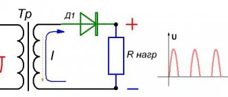
The circuits for connecting power devices are different. To rectify the mains voltage, they are divided into single-phase and multiphase, half-wave and full-wave. Most of them are single phase. Below is the design of such a half-wave rectifier and two voltage graphs on a timing diagram.
Alternating voltage U1 is supplied to the input (Fig. a). On the right side of the graph it is represented by a sine wave. The diode state is open. Current flows through the load Rн. During the negative half-cycle the diode is closed. Therefore, only a positive potential difference is supplied to the load. In Fig. its time dependence is reflected. This potential difference operates during one half-cycle. This is where the name of the scheme comes from.
The simplest full-wave circuit consists of two half-wave circuits. For this rectification design, two diodes and one resistor are sufficient.
Diodes only allow positive AC current to pass through. The disadvantage of the design is that during the half-cycle the alternating potential difference is removed only from half of the secondary winding of the transformer.
If you use four diodes in the design instead of two, the efficiency will increase.
Rectifiers are widely used in various industries. A three-phase device is used in automobile generators. And the use of the invented alternating current generator contributed to reducing the size of this device. In addition, its reliability has increased.
In high-voltage devices, high-voltage poles, which are composed of diodes, are widely used. They are connected in series.
AC rectification using rectifier diodes
AC rectification is one of the main processes in radio electronics. In the rectifier device, alternating current energy is converted into direct current energy. Any rectifier is a consumer of alternating current energy and a generator of direct current.
Since semiconductor diodes conduct current well in the forward direction and poorly in the reverse direction, most semiconductor diodes are used to rectify alternating current.
The simplest circuit for rectifying alternating current is shown in Figure 2.19, a. It contains a series-connected alternating EMF generator (e), a diode D and a load resistor Rн, which can also be connected to another wire, as shown by dashes. This circuit is called half-wave. It would be more correct to call it single-phase single-cycle, since the alternating EMF generator is single-phase and the current passes through it only in one direction once per period (one cycle per period). Other, more complex circuits for rectification (two-phase, three-phase, push-pull, etc.), as a rule, are a combination of several single-phase single-cycle circuits.
Figure 2.19 – Rectifier circuits with a semiconductor diode
In rectifiers for powering REA, the alternating EMF generator is usually a power transformer connected to the electrical network (Figure 2.19, b). Instead of a transformer, an autotransformer is sometimes used. In some cases, the rectifier is powered from the mains without a transformer. The role of the load resistor Rн, i.e., the consumer of direct current energy, in practical circuits is played by those circuits or devices that are powered by the rectifier. When rectifying high-frequency currents, for example, in detector cascades of radio receivers, a high-frequency transformer or a resonant oscillating circuit serves as a generator of alternating EMF, and a resistor with high resistance serves as a load.
The simplest rectifier works as follows. We will assume that the generator produces a sinusoidal EMF e = Etsin wt and its internal resistance can be neglected (if not, then it is taken into account in the usual way). During one half-cycle, the voltage for the diode is direct and a current passes, creating a voltage drop andR across the resistor Rн. During the next half-cycle, the voltage is reversed, there is practically no current and R = 0. Thus, a pulsating current passes through the diode, load resistor and generator in the form of pulses lasting half a cycle and separated by intervals also of half a cycle. This current is called rectified current. It creates a rectified voltage across the resistor Rн. By tracing the direction of the current, it is not difficult to establish the polarity of this voltage: the cathode side of the diode is plus, and the anode side is minus.
The graphs in Figure 2.20 clearly illustrate the processes in the rectifier. The alternating EMF of the generator is depicted as a sinusoid with amplitude Et (Figure 2.20, a). As a rule, the load resistance is many times greater than the resistance of the diode, and then the nonlinearity of the diode can be neglected (the operating characteristic is close to linear). In this case, the rectified current has a pulse shape close to a half-sine wave with a maximum value of Imax (Figure 2.20, b). The same current graph on a different scale depicts the rectified voltage uR, since uR = iRн. It is enough to multiply the current values by Rн to obtain a voltage curve.
Figure 2.20 – Operating principle of the simplest rectifier
| (2.3) |
The graph in Figure 2.20, c depicts the voltage across the diode. Sometimes it is mistakenly considered sinusoidal or identified with the voltage of the source of alternating EMF. In fact, this voltage has a non-sinusoidal shape. Its amplitudes of positive and negative half-waves are sharply unequal. The amplitude of positive half-waves is very small. This is explained by the fact that when direct current passes, most of the source voltage drops across the load resistor Rн, the resistance of which significantly exceeds the resistance of the diode. In this case
Up max = Em – URmax = Em – ImaxRн<m
For conventional semiconductor diodes, the forward voltage is no more than 1–2 V. For example, let the source have an effective voltage E = 200 V and Em = E = 280 V. If Upr max = 2 V, then URmax = 278 V. If the source voltage (e.g. 200 V) was applied entirely to the diode, this would mean that there was no voltage drop across the resistor Rn. But this is only possible when Rн=0. Then the current would be unacceptably high and the diode would fail.
The simplest rectifier works as follows. We will assume that the generator produces a sinusoidal EMF and its internal resistance can be neglected (if not, then it is taken into account in the usual way). During one half-cycle, the voltage for the diode is direct and a current passes, creating a voltage drop UR across the resistor Rн. During the next half-cycle, the voltage is reversed, there is practically no current and UR = 0. Thus, a pulsating current passes through the diode, load resistor and generator in the form of pulses lasting half a cycle and separated by intervals also of half a cycle. This current is called rectified current. It creates a rectified voltage across the resistor Rн.
With a negative half-wave of the supplied voltage, there is practically no current and the voltage drop across the resistor Rн is zero. The entire source voltage is applied to the diode and is the reverse voltage for it. Thus, the maximum value of the reverse voltage is equal to the amplitude of the source emf.
Let's take a closer look at rectified voltage (everything that will be shown for it also applies to rectified current). From the graph in Figure 2.20, b it is clear that this voltage pulsates strongly. There is no voltage at all for half a period. The useful part of such a voltage is its constant component, or the average value of Uav. For a half-sinusoidal pulse with a maximum voltage value Umax, the average value for a half-cycle
| (2.4) |
Uav = 2Umax/p = 0.636 Umax.
Since there is no voltage at all in the second half-cycle, the average value for the entire period is half as much:
Uav = Umax/p = 0.318 Umax. (2.5)
Approximately Uav is considered equal to 30% of the maximum value. This approximation is acceptable, since the actual shape of the pulses is always slightly different from a half-sine wave. Since the voltage drop across the diode is very small, we can consider
Umax "Em and Uav" 0.3 Em. (2.6)
Subtracting its average value from the rectified pulsating voltage, we obtain the variable component U~, which has a non-sinusoidal shape. For it, the zero axis is a straight line depicting the constant component (Figure 2.21, a).
Figure 2.21 - DC and AC components of rectified voltage
The half-waves of the alternating component are shaded. The positive half-wave represents the upper two-thirds of a half-sine wave, while the negative half-wave has a shape close to a trapezoid. The duration of these half-waves is not the same, but the areas limited by them are equal, since there is no longer a constant component.
The alternating component is the “harmful” part of the rectified voltage. To reduce it in the load resistor, i.e., to smooth out the ripples of the rectified voltage, special smoothing filters are used. Figure 2.21, b shows the variable component. It consists of a series of harmonics. The most difficult one to reduce is the first harmonic (shown as a dashed sine wave).
The smoothing filter uses high-capacity capacitors through which the alternating current component is branched off so that as little as possible of it passes to the load. Often, chokes are also installed in these filters, i.e., coils with high inductance that prevent the passage of the alternating component to the load. The higher the pulsation frequency, the lower the resistance of the capacitors and the greater the resistance of the chokes, and therefore, the more efficiently the smoothing filter works.
If the filter attenuates the first harmonic of ripple well, then higher harmonics are suppressed even better. And since they are also smaller in amplitude than the first harmonic, it is practically necessary to take care of suppressing only the first harmonic, which is the main “enemy”.
Um1= 0.5 Umax = 1.57 Uav. (2.7) In the simplest rectifier circuit, the amplitude of the first pulsation harmonic Um1 is very large - more than the useful constant component:
Rectified voltages with such large ripples are generally unsuitable for practical purposes. More complex rectifier circuits provide some reduction in ripple. The simplest method of smoothing ripples is to use a filter in the form of a capacitor of a sufficiently large capacity that shunts the load resistor Rн (Figure 2.19, b). Including a capacitor significantly changes the operating conditions of the diode.
A capacitor smooths out ripples well if its capacitance is such that the condition is met
1/(wС)<н. (2.8)
During some part of the positive half-cycle, when the voltage across the diode is forward, a current passes through the diode, charging the capacitor to a voltage close to Em. At a time when no current passes through the diode, the capacitor discharges through the load Rн and creates a voltage across it, which gradually decreases. In each subsequent positive half-cycle, the capacitor is recharged and its voltage increases again.
The capacitor charges quickly through the relatively low resistance of the diode. Discharge to a large load resistance occurs much more slowly. As a result, the voltage across the capacitor and the load connected in parallel with it pulsates slightly. In addition, the capacitor sharply increases the DC component of the rectified voltage. In the absence of a capacitor Uav »0.3 Em, and in the presence of a capacitor of sufficiently large capacity, Uav approaches Eti and can be equal to (0.80 ¸ 0.95) Eti even higher. Thus, in a single-phase single-cycle rectifier, the capacitor increases the rectified voltage by about 3 times. The more C and Rn, the slower the capacitor discharges, the less pulsation and the closer Ucpk Et. If the load is turned off altogether (idling mode, i.e. Rн = ¥), then a constant voltage without any ripple, equal to Em, is obtained on the capacitor.
The operation of a rectifier with a smoothing capacitor is illustrated in Figure 2.22, which shows graphs of the emf of the source e, the current through the diode i and the voltage across the capacitor iC, equal to the voltage across the load iR.
The voltage on the capacitor is applied plus to the cathode, minus to the anode of the diode. Therefore, the voltage across the diode is equal to the difference between the source emf and the capacitor voltage:
Ud = e – uC (2.9)
Since the value of uC is close to Em, the voltage becomes direct only during the part of the positive half-cycle when e exceeds is (near the value of Em). During these short periods of time, current passes through the diode in the form of pulses, recharging the capacitor. During the rest of the positive half-cycle and during the negative half-cycle, the voltage ud is reversed, there is no current and the capacitor is discharged to the load Rн.
Figure 2.22 – Smoothing ripples using a capacitor
The maximum reverse voltage on the diode is obtained at a negative amplitude of the EMF, when e = –Et. Since the capacitor voltage is also close to Et, the maximum reverse voltage is close to the value of 2Et. If the load circuit is open (idle), then the maximum reverse voltage is exactly 2Et. Thus, the presence of a capacitor doubles the reverse voltage, so the diode must be selected so that it can withstand this reverse voltage.
If it is necessary to reduce pulsation, but the resistance R is small, then an excessively large capacitance of the capacitor is required, i.e., it is practically impossible to smooth out pulsations with one capacitor. You have to include an additional smoothing filter, consisting of a choke with a large inductive reactance and another capacitor (or an even more complex filter).
It should be noted that a short circuit of the load is very dangerous, which, in particular, occurs when the smoothing filter capacitor breaks down. Then the entire source voltage will be applied to the diode and the current will become unacceptably large. Thermal destruction of the diode occurs.
The advantage of semiconductor diodes compared to vacuum ones is not only the absence of cathode heating, but also the low voltage drop across the diode at forward current. Regardless of the current value, i.e., the power for which the semiconductor diode is designed, the forward voltage is tenths of a volt or slightly more than 1 V. Therefore, the efficiency of rectifiers with semiconductor diodes is higher than with vacuum ones. When higher voltages are rectified, the efficiency increases, since in this case the voltage loss of about 1 V on the diode itself is not significant. For example, if when rectifying a voltage of 100 V, 1 V is lost on the diode, then the efficiency is about 99% (taking into account other losses, it will, of course, be somewhat lower).
Thus, semiconductor diodes are more economical than vacuum diodes and emit less heat during operation, which is very important for other elements located nearby. In addition, semiconductor diodes have a very long service life. But their disadvantage is the relatively low maximum reverse voltage - several hundred volts, while for high-voltage vacuum diodes it can be tens of kilovolts.
Diodes are used in any rectifier circuits. If the smoothing filter starts with a large capacitor, then when the alternating voltage is turned on, a current pulse passes through the capacitor, often exceeding the permissible value of the forward current of the diode. To reduce such current, a limiting resistor with a resistance of a few or tens of ohms is sometimes connected in series with the diode.
In diodes operating in rectifier mode, when the voltage polarity changes, significant reverse current pulses can be observed (Figure 2.23). They arise for two reasons. Firstly, under the influence of reverse voltage, a current pulse is obtained that charges the barrier capacitance of the np junction. The larger this capacity, the greater the impulse. Secondly, with reverse voltage, a discharge of the diffusion capacitance occurs, i.e., the resorption of minority carriers accumulated in the n- and p-regions. During the passage of direct current, these carriers are injected through the junction and, without having time to recombine or leave, accumulate in the n- and p-regions. Almost the main role is played by the larger charge accumulated in the base region.
Figure 2.23 – Diode reverse current pulses
For example, if the electron concentration in the n-region is significantly greater than the hole concentration in the p-region, then the n-region is the emitter and the p-region is the base. The injection of electrons from the n-region to the p-region prevails over the injection of holes in the opposite direction. Therefore, electrons accumulate mainly in the p-region. When the voltage is reversed, this charge is dissolved, i.e., the electrons begin to move in the opposite direction - from the p-region to the n-region. A reverse current pulse occurs. The greater the forward current, the stronger the flow of injected carriers (electrons in this example) and the greater the charge formed by them, and therefore the greater the reverse current pulse. When this accumulation of carriers dissolves and the charge of the barrier capacitance is practically exhausted, then only a negligible reverse current will remain, which can be ignored.
As the frequency increases, the reverse current pulse increases. This is because at higher frequencies the reverse voltage increases faster. Consequently, a higher current, i.e., faster, charges the barrier capacitance. In other words, capacitance decreases with increasing frequency and the reverse current increases accordingly. The resorption of charges formed by injected carriers also occurs faster, and from this the reverse current pulse also increases.
At low frequencies, the reverse current pulse is very small and its duration is many times less than a half-cycle. And at a certain high frequency, the reverse current pulse can have approximately the same amplitude as the forward current pulse, and it lasts throughout the entire half-cycle. If the area of the forward and reverse current pulses is the same, then the constant component (average value) of the current will become equal to zero, i.e., rectification will stop. In practice, it is recommended to use diodes for rectification only up to such a high frequency limit at which the direct component of the rectified current is reduced by no more than 30% compared to its value at low frequency.
As the temperature increases, the resistances Rnp and Ro6p of the diodes decrease, but this usually has little effect on rectification. The fact is that the forward current is determined by the load resistance Rн, which is usually many times greater than Rnp, and Ro6p, even for a heated diode, is still quite large compared to Rн, and therefore the reverse current remains small compared to the forward one.
The operation of diodes in low-frequency rectifying devices is characterized by several parameters. These include the period-average values of the forward current Ipr av and the corresponding voltage drop on the diode Upr av, the reverse voltage Urev. avg and the corresponding reverse current Irev avg. The current Ipr cp is often called the rectified current, and the maximum permissible (limit) values of the reverse voltage Uo6p are very important. max, direct (or rectified) current Ipr max and housing temperature tcor max, as well as the maximum operating frequency fmax.
Pulse devices
A pulsed device is a device whose transition time from one state to another is short. They are used to work in pulse circuits. Such devices differ from their rectifier analogues by their small pn junction capacitances.
For devices of this class, in addition to the parameters indicated above, the following should be included:
- Maximum pulse forward (reverse) voltages, currents,
- Direct voltage installation period,
- Recovery period of the device's reverse resistance.
Schottky diodes are widely used in high-speed pulse circuits.