Automation of lighting supply in an apartment, house or street is achieved through the use of photo relays. If configured correctly, it will turn on the light when it gets dark and turn off during daylight hours. Modern devices contain a setting that allows you to set the trigger depending on the light level. They are an integral part of the “smart home” system, taking on a significant part of the responsibilities of the owners. The photo relay circuit first of all contains a resistor that changes the resistance under the influence of light. It is easy to assemble and configure with your own hands.
Operating principle
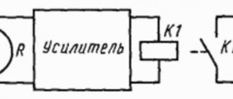
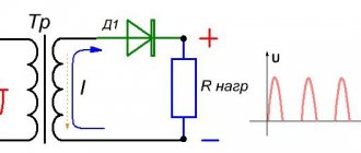
The connection diagram for a photo relay for street lighting includes a sensor, an amplifier and an actuator. Photoconductor PR1 changes resistance under the influence of light. At the same time, the magnitude of the electric current passing through it changes. The signal is amplified by a composite transistor VT1, VT2 (Darlington circuit), and from it goes to the actuator, which is the electromagnetic relay K1.
In the dark, the resistance of the photosensor is several mOhms. Under the influence of light it decreases to several kOhms. In this case, transistors VT1, VT2 open, turning on relay K1, which controls the load circuit through contact K1.1. Diode VD1 does not allow self-induction current to pass when the relay is turned off.
Despite its simplicity, the photo relay circuit is highly sensitive. To set it to the required level, resistor R1 is used.
The supply voltage is selected according to the relay parameters and is 5-15 V. The winding current does not exceed 50 mA. If it is necessary to increase it, more powerful transistors and relays can be used. The sensitivity of the photo relay increases with increasing supply voltage.
Instead of a photoresistor, you can install a photodiode. If a sensor with increased sensitivity is needed, circuits with phototransistors are used. Their use is advisable in order to save electricity, since the minimum response limit of a conventional device is 5 lux, when surrounding objects are still distinguishable. The threshold of 2 lux corresponds to deep twilight, after which darkness sets in 10 minutes later.
It is advisable to use a photo relay even with manual lighting control, since you can forget to turn off the light, and the sensor will “take care” of this on its own. It is easy to install and the price is quite affordable.
Installation work
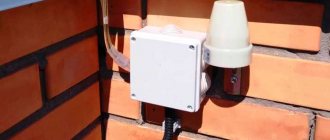
Connecting the photo relay can be done with your own hands, without involving professionals. In the case of sealed device models, fastening will be performed using an external bracket. Installation of photo relays for street lighting is carried out using screws for connecting elements mounted in holes in the device body. The remote-type sensor is installed outside the house. There are a number of rules for connecting a photo relay to lighting:
- for installation it is necessary to choose a place illuminated by the sun;
- shadows from canopies, fences, and high walls should be avoided;
- It must be taken into account that in the warm season, budding leaves on trees can become an obstacle to the normal functioning of the equipment.
If necessary, any retrofitting of the device can be done with your own hands, without resorting to the services of electricians.
Proper adjustment of the photo relay is performed as follows. There is a round knob under the photosensor cover; turning it changes the sensitivity of the sensor. It should be set to the first extreme position. Then you need to connect the photocell to the electrical network and, at the time when you want to turn on the street lighting, turn the lever until the sensor signals. Leaving the lever in the designated position will ensure that the system starts properly at the given lighting level.
Characteristics of photocells
The choice of photo relay is determined by the following factors:
- photocell sensitivity;
- supply voltage;
- switching power;
- external environment.
Sensitivity is characterized as the ratio of the resulting photocurrent to the external light flux and is measured in μA/lm. It depends on frequency (spectral) and light intensity (integral). To control lighting in everyday life, the last characteristic is important, depending on the total luminous flux.
The rated voltage can be found on the device body or in the accompanying document. Foreign-made devices may have different supply voltage standards.
The load on its contacts depends on the power of the lamps to which the photo relay is connected. Lighting photo relay circuits can provide for direct switching of lamps through sensor contacts or through starters when the load is high.
Outdoors, the twilight switch is placed under a sealed transparent cover. It provides protection from moisture and precipitation. When working in cold periods, heating is used.
How does a photosensitive machine work?
A device that is triggered when illumination changes to a threshold value can be made on different element bases, but has approximately the same structure.
- A semiconductor device that changes its parameters or generates an emf under the influence of incident light can be used as a photosensitive element. Thus, a photoresistor, when irradiated by photons, changes its resistance, a photodiode creates an emf, etc. The light level sensor can be built into the device body or be remote.
- The converter transforms the variable value into an electrical parameter that is convenient to work with. If a photoresistor is used as a photocell, its resistance is converted into voltage.
- The amplifier amplifies the voltage to values at which the level of interference and interference becomes insignificant.
- The threshold device compares the set voltage value with the voltage coming from the amplifier. If it becomes greater or less than the reference level, the comparator changes its state from one to zero or vice versa.
- Delay timer. Does not allow the relay to operate if the duration of the control signal is less than the specified one.
- Executive device. When the state of the comparator changes, caused by the passage of illumination through a given threshold, it produces a control signal that can be used to control external devices. In most household appliances, this signal is the “dry contact” of the built-in electromagnetic relay. But there may also be a discrete voltage from a solid-state switch, a change in the state of an open collector transistor, etc.
Some nodes can be combined. Thus, the converter and amplifier are combined into one circuit. There may not be a delay timer in simple relays, but it has a useful function, which is discussed below. The element base may be different - analogue or digital. But the principle of operation remains: comparing the actual illumination level with a given threshold and issuing a control signal.
Block diagram of a photo relay.
Photo relay FR-2
Factory-made models are widely used in automation devices, for example, to control street lighting. You can often see lights burning during the day that you forgot to turn off. With photo sensors, there is no need for manual lighting control.
The industrially manufactured photo relay circuit fr-2 is used for automatic control of street lighting. Here also the switching device is relay K1. The FSK-G1 photoresistor with resistors R4 and R5 are connected to the base of transistor VT1.
Power is supplied from a single-phase 220 V network. When the illumination is low, the resistance of FSK-G1 is large and the signal based on VT1 is not enough to open it. Accordingly, transistor VT2 is also closed. Relay K1 is energized and its operating contacts are closed, keeping the lamps lit.
When the illumination increases to the operating threshold, the resistance of the photoresistor decreases and the transistor switch opens, after which relay K1 turns off, opening the lamp power circuit.
Main technical characteristics
Whether it’s a lawn or flower beds, everything will be thoroughly moistened overnight without your intervention. Note!
You can proceed to setting up the connected equipment. Each of the above photocells reacts differently to light: resistor type - changes the value of its resistance, as a result of which the light turns on or off; The transistor type regulates when an electrical signal is irradiated with light. An example of a mounted and connected relay. In addition, the lighting system performs a security function, since it can turn on the light in the absence of the owners.
What could be the reason??? When they began to transfer street lighting from switches to photo relays through the control of a magnetic starter coil to one relay, a problem arose.
Well, plus pay attention to the permissible load. Logically, there is almost no load from the coil, but in fact the “return” current does its job. We strip the conductors of insulation by mm in order to connect them to the terminals.
Connection diagrams
However, most models are equipped with conventional mechanical toggle switches that adjust the light sensitivity threshold. To understand which sensor to choose, the load power is taken into account - the total power of light sources and lamps. But you don’t need to run wires to the switchboard.
The installation location depends on the lighting; try to choose an area where nothing prevents the sun's rays from hitting the working surface of the device, otherwise interference will begin on the photodiode and the device will not work correctly. Some samples turn on when there is any movement opposite the installation site. Each of the above photocells reacts differently to light: resistor type - changes the value of its resistance, as a result of which the light turns on or off; The transistor type regulates when an electrical signal is irradiated with light.
According to the circuit, zero seems to go to both the relay and the light bulb. I connected the FR photo relay according to the circuit to illuminate the entrance consisting of 5 LED lamps, but when activated, the light in the entrance begins to blink.
However, you can use little tricks to make the task easier: Use a piece of plastic pipe, preferably black, cm long, with an increased diameter, to protect the photo relay or sensor from the light coming from windows or streetlights. This way you can choose an easier installation method; When installing the device, remember that its minimum response limit will be 5 Lux. The cutting angle is about from the pillar or wall. In these devices, the sensor element is located in a transparent hermetically sealed housing. HOW TO SCARE A NIGHT THIEF. ONE OF THE WAYS!!!
Types of photo relay
The choice of models is large enough so that you can choose the right one:
- with a remote sensor located outside the product body, to which 2 wires are connected;
- Lux 2 - a device with high reliability and quality level;
- photo relay with a 12 V power supply and a load not exceeding 10 A;
- module with a timer mounted on a DIN rail;
- IEC devices from a domestic manufacturer with high quality and functionality;
- AZ 112 - automatic machine with high sensitivity;
- ABB, LPX are reliable manufacturers of European quality devices.
Device selection criteria
To choose a photo relay, you need to consider several points:
- Supply voltage. It does not fundamentally affect consumer qualities, but it is convenient to power the device from the same voltage that is used for the controlled lighting device. It is even more convenient to have a photo relay with dual power supply - from a 220 volt network and from a low DC voltage.
- Design for connecting a light sensor to a street lighting relay. The photocell can be built-in or remote. The first option is cheaper, the second is more convenient to install.
- Power of the output contact group. If it does not allow you to switch the existing load directly, you will have to connect it through an intermediate relay or magnetic starter.
- Degree of protection. Depends on the intended installation location of the main unit. If it is installed indoors, IP40 is sufficient. If outdoors, IP42 or IP44 will be required, and in some cases IP65.
Power table of the main manufacturers.
| Photo relay type | FR-601 | Euroautomation F&F AZH | Smartbuy | FR-05 |
| Load capacity, W | 1100 | 1300 | 2200 | 2200 |
Other characteristics (range of adjustment of the turn-on delay, etc.) are selected based on local conditions and are not of a fundamental nature.
An example of installation of FR-601 in a wooden house.
Methods for connecting a photo relay
Before purchasing a sensor, you need to calculate the power consumed by the lamps and take it with a margin of 20%. With a significant load, the circuit of a street photo relay provides for the additional installation of an electromagnetic starter, the winding of which must be switched on through the contacts of the photo relay, and switch the load with power contacts.
This method is rarely used at home.
Before installation, the supply voltage of ~220 V is checked. The connection is made from a circuit breaker. The photo sensor is installed in such a way that the light from the flashlight does not fall on it.
The device uses terminals to connect wires, which makes installation easier. If they are missing, a junction box is used.
Thanks to the use of microprocessors, the connection diagram of the photo relay with other elements has acquired new functions. A timer and a motion sensor were added to the action algorithm.
It is convenient when the lamps automatically turn on when a person passes along a landing or along a garden path. Moreover, operation occurs only in the dark. Due to the use of a timer, the photo relay does not react to headlights from passing cars.
The simplest connection diagram for a timer with a motion sensor is serial. For expensive models, special programmable circuits have been developed that take into account various operating conditions.
Subtleties of connection
Existing electrical connection diagrams for photo relays are different. Both simple and complex. All wire connections are made in a junction box located outside in a convenient place for access.
In a private home, you can get by with the following:
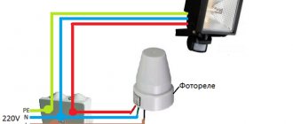
- The neutral wire and phase are connected to the photo relay input terminals. At the output, the current-carrying wire is connected to the lamp (lantern). The other end of the cable is connected to a switch or to the bus of a lighting control box with a photo relay.
- When using a high-power lantern with chokes as part of the design, a single-phase starter is added to the connection diagram.
- If it is necessary for the light to turn on when a person is in a certain place (at the gate, at the entrance to the house, in the toilet), a motion sensor is included in the circuit after the photo relay.
As for the wires, there are always three of them, and they differ in the color of the insulation shell.
During the connection process, you should remember simple rules that are suitable for connecting any devices to the electrical network:
- Red is always connected to the final current consumer (flashlight, lamp):
- Green (blue) is always neutral, grounding;
- Brown or black is current-carrying, phase.
Photo relay for street lighting
To connect the photo relay, the circuit is applied to its body. It can be found in the documentation for the device.
Three wires come out of the device.
- Neutral conductor - common for lamps and photo relays (red).
- Phase - connects to the device input (brown).
- Potential conductor for supplying voltage from the photo relay to the lamps (blue).
The device operates on the principle of phase interruption or phase switching. Color markings may vary from manufacturer to manufacturer. If there is a ground conductor in the network, it is not connected to the device.
In models with a built-in sensor, which is located inside a transparent case, the street lighting operates autonomously. You just need to supply power to it.
Options with remote sensors are used when the electronic content of the photo relay is conveniently placed in the control panel with other devices. Then there is no need for stand-alone installation, power wiring and maintenance at height. The electronic unit is placed indoors, and the sensor is taken outside.
How to connect a photo relay: connection diagrams
To connect a photo relay to an LED spotlight, you must carefully study the instructions contained in the data sheet. Most photo sensors have a circuit on the body. Since the photo relay is similar in functionality (supply and power off) to a traditional switch, the installation also differs little.
Equipment with a built-in photocell can be connected via a distributor or without it. The distributor is used during repairs that involve replacing wiring. In such a situation, it is possible to draw a new line. If repairs are not carried out, it is not profitable to drill the walls for new wiring.
Features of photo relay for street lighting: diagram
When installing a photo relay outdoors, you need to take into account some factors.
- Availability of supply voltage ~220 V and matching power of contacts and load.
- Installation of devices near flammable materials and in an aggressive environment is not allowed.
- The base of the device is located at the bottom.
- There should be no moving objects in front of the sensor, such as tree branches.
The wires are connected through an outdoor junction box. It is fixed next to the photo relay.
How to connect a device to a street lamp: diagrams and principles
When connecting a simple device, you need to familiarize yourself with its design. The main element is a photodiode, which can be located outside or inside the housing. In the first case, the sensor is mounted outdoors, and the electronic unit is connected to an electrical panel indoors. If the sensitive part is located internally, the device is mounted outdoors.
The device is small in size and easy to mount
Knowing the design features of the device allows you to connect it to the flashlight as efficiently as possible. Therefore, it is important to determine the type of photo relay, purchase a high-quality device, select a circuit, and then begin connecting the sensor.
Photo relay on the diagram
The correct connection diagram greatly facilitates self-installation of the device. In the electrical diagram, the photodiode is presented in the form of a conventional graphic symbol, which is a triangle on the axis of symmetry with arrows directed from top to bottom. On simple diagrams, the device can be designated as a circle or rectangle with the inscription “FR”.
The arrows in the diagram symbolize the reflection of light
Connection
The bracket with the device is mounted in a shaded place. Tree foliage, canopies, and precipitation should not affect the operation of the device. After determining the location, you need to find out the number of lamps for which control is required. One photo relay is mounted per light source. If you use a large number of flashlights, then it is best to use a controller. It receives a signal from a photosensor and allows you to control several lamps simultaneously.
The connection diagram for one lamp is very simple
The design of the device may include terminals, which simplifies connection. They are necessary for clamping wires. The cable of each color is connected to the corresponding wire of the lamp and power circuit. If there are no terminals, then a junction box should be installed. The device body must be protected from moisture and precipitation. Well-known manufacturers indicate on the packaging or in the instructions the connection diagram of the element.
Selecting a photo relay
- The ability to adjust the response threshold allows you to adjust the sensitivity of the sensor depending on the time of year or in cloudy weather. The result is energy savings.
- A minimum of labor costs is required when installing a photo relay with a built-in sensitive element. This does not require any special skills.
- The timer relay is well programmable for its needs and operation in the set mode. You can set the device to turn off at night. Indication on the device body and push-button control make settings easy.
What should you consider when connecting?
When choosing specific equipment for connecting a floodlight, it is important to consider a number of factors. Let's look separately at the light sensor, motion sensor and the spotlight itself.
The motion sensor is selected according to its coverage area; it is important that the area where people move around turns on the spotlight. Different models have different angles - 120º, 90º, 60º, the selection principle is shown in the figure below:
Rice. 5. Motion sensor angle
In addition, motion sensors can be divided according to their operating principle into:
- Ultrasonic sensors are the simplest and most affordable, are not exposed to atmospheric factors, but are picky about sudden gusts, and are characterized by a small coverage angle;
- Microwave sensors are practically unaffected by environmental factors, operate not only on temperature, and have small dimensions. But their main disadvantage is their harmful effect on living organisms.
- Infrared sensors - carry out measurements using waves and react to heat. They are fairly accurate sensors that are safe for humans, but infrared sensors suffer from false alarms.
The sensitivity of the sensor for street lighting is very important, since the spotlight can be triggered by a flying bird or a running cat. Therefore, it is adjusted experimentally; the sensitivity of the sensors is switched using the SENS function. In this sensitivity setting menu, you can already lower the parameter in the inclusion range in the low or - option and similarly increase it with the high or + option.
The spotlight is selected according to the power of the luminous flux and the angle of dispersion. The most efficient, in terms of energy consumption, are LED floodlights, while halogen floodlights are among the most costly both in terms of price and service life. Depending on the location, the spotlight can be mounted vertically or horizontally. When installed on a wall, the height can be from 2.5 to 3 m, the height is determined by local conditions.
The delay time is selected depending on how long the relay contacts must remain closed after the sensor is triggered. As a rule, the time range is adjusted from 10 seconds to 10 minutes.
Do-it-yourself installation and configuration: step-by-step instructions
To connect a photo relay to a lamp that is already on a pole, turn off the power supply in the dashboard and check the field for voltage.
Sequence of actions when installing the device:
- stretch the power cord in the place where the switch to be connected will be installed;
- stripping veins 10-12 mm;
- grounding to the socket (if the lamp body is metal).
- connecting wires according to the diagram;
- drill holes in the body;
- a piece of wire for connecting to the LED backlight;
- fixing gaskets in the holes to protect against moisture and dust;
- connecting cables to LED lighting;
- stripping of insulation 10-12 mm;
To connect the photosensor, it is best to use a three-wire cable. Place it on a pole or wall so that the holes are at the bottom. This arrangement will protect from dust and moisture.
you can continue configuring the connected equipment. The set includes a black bag to simulate the night. There is a regulator on the body that allows you to select the light intensity at which the lamp should light up. The closer the knob is to minus, the later the LED indicator will light up.
The last step is to connect to the network in the dashboard.
If you do not have knowledge in the field of electrical engineering, it is better to entrust the connection to a specialist.
Technical specifications
The most important criterion when choosing is the supply voltage.
Important technical parameters:
- design and degree of protection;
- ability to work with precipitation;
- photosensitivity, the ability to regulate it.
- level of protection against dust and foreign bodies;
- ability to maintain temperature;
Equipment for foreign countries is designed for the standard voltage of 110 or 127 volts for a particular country. Such light sensors cannot operate on a 220 or 380 volt network.
Performance characteristics
When purchasing, you need to focus on the type of lamp and installation location.
Light bulbs in lamps are:
- incandescence (active load);
- fluorescent, LED (reactive load);
- mercury, sodium (an additional circuit is required to protect against inrush current fluctuations).
Models with a built-in photocell are designed for outdoor installation. They are sealed, with a degree of protection from IP 65, operating temperatures from -25 to + 40 ° C. Equipment with a remote sensor is purchased if it can be placed in the dashboard. With this option, a degree of protection up to IP 44 is sufficient.
The load power is taken into account if it is necessary to connect several lamps to one photosensor. The switch will last longer if its power is 20% higher than the total power of the lighting equipment.
Standard illumination range 2-50 Lux. You should not buy equipment without setting this parameter. The exception is connection to an LED projector and the absence of strict energy saving requirements.
The weight and dimensions of the photosensor are also important. Larger models with built-in transformer. The snack takes up a lot of space. When choosing a device with a separate sensor, the available space on the instrument panel is taken into account.
If there are one or two lamps on the site, then an unregulated relay to which the lamps are connected directly is quite suitable. If there are a large number of devices connected in parallel, the switch will not be able to withstand the current flowing through it. You should buy a model with a magnetic starter.
Possibilities
The functionality of the twilight switch depends on its type:
- to control a line of LED spotlights, you should purchase a model with power switches that transmit commands and a motion sensor;
- for a large summer cottage or apartment building, a photo relay with a threshold regulator is suitable, allowing you to set the indicators depending on the season;
- for an industrial building or warehouse it is necessary to purchase a model with an external photocell;
Important! Equipment with a timer that can be programmed at your discretion (the device operates according to a certain time and schedule) allows you to save as much as possible on your energy bills).