METHOD FOR DETERMINING ROTOR SLIP OF AN INDUCTION MOTOR
The invention relates to the field of operation of asynchronous electric motors and can be used to determine the amount of slip of the electric motor.
The method includes estimating the amount of rotor slip according to a graph of the dependence of slip on the amount of current consumed, digital recording of the instantaneous amplitude of the consumed current over time on one of the phases of the power cable of an asynchronous electric motor, using two bandpass filters to isolate the fundamental harmonic and the high-frequency component of the consumed current signal. The network frequency is calculated from the fundamental harmonic, then the boundaries of the ranges for searching frequencies are determined. After that, excluding from the frequency ranges the frequencies caused by the saturation of the magnetic circuits of the rotor and the current sensor, they find the frequencies of the first-order tooth harmonics, from which two values of rotor slip are obtained, the rotor slip of an asynchronous electric motor is determined by the arithmetic mean of these values and a conclusion is made about the reliability of the result by comparing the two slip values calculated from the frequencies of the tooth harmonic rotor of the first order. The technical result is to increase the accuracy and reliability of the result obtained, eliminating the need for additional measurements to obtain a reliable slip value. 2 ill. A method for determining the rotor slip of an asynchronous electric motor, including estimating the amount of rotor slip, digital recording of the instantaneous amplitude of the consumed current over time on one of the phases of the power cable of the asynchronous electric motor, characterized in that the fundamental harmonic and the high-frequency component of the consumed current signal are isolated using two bandpass filters, in which there are first-order tooth harmonics of the rotor, calculate the frequency of the network from the fundamental harmonic, then determine the boundaries of the ranges to search for frequencies caused by the first-order tooth harmonics of the rotor, after which, excluding from the ranges the frequencies caused by the saturation of the magnetic circuits of the rotor and the current sensor, find the frequencies of the tooth harmonic first order, from which two values of rotor slip are obtained, the rotor slip of an asynchronous electric motor is determined by the arithmetic mean of these values and a conclusion is made about the reliability of the result by comparing two slip values calculated from the frequencies of the tooth harmonic rotor of the first order.
The invention relates to the field of operation of asynchronous electric motors and can be used to determine the amount of slip of the electric motor.
Methods for determining the slip of asynchronous electric motors with a squirrel-cage rotor are widely known (GOST 7217-87 (ST SEV 168-85). Electric rotating machines. Asynchronous motors. Test methods. - Introduction 1988-01-01. - M.: Standards Publishing House , 1987. - 53 p.):
- stroboscopic method: for this, marks are applied on the motor shaft, the number of which is equal to the number of pairs of poles. Illuminating the shaft with a stroboscopic lamp powered from the same network as the engine under test, measure the time it takes for a certain number of marks to pass past the stationary pointer, counting the passage of the mark at the moment the stopwatch starts as zero,
- a method for determining slip using an inductive coil: the coil is placed at the end of an asynchronous electric motor, having previously determined the position at which the galvanometer needle makes the most noticeable swings, and the time of a certain number of oscillations is measured.
These methods are unsuitable for use in operating mode, since they require the installation of additional elements near the high-voltage stator winding or on the shaft of an asynchronous electric motor. Therefore, they found application only when testing on an engine taken out for repair.
The “Method for determining rotor slip of an asynchronous electric motor...” (Russian Federation patent for invention No. 2209442, IPC G01R 31/34, 2003) was adopted as a prototype, allowing slip to be determined in operating mode. It is based on isolating, using the Hilbert transform, from the stator phase current a low-frequency envelope having a double slip frequency 2(fc-fвp), where fc is the network frequency, fвp is the rotor rotation frequency, and then using the Fourier transform, determining the oscillation frequency of the envelope and Taking the network frequency to be 50 Hz, the slip value is calculated.
The disadvantages of this method are:
- low reliability of the obtained slip value, since the low-frequency envelope of the consumed current is taken as a source carrying information about the slip value, which may be absent (with magnetic and electrical symmetry of the asynchronous electric motor (the resistance of the rotor winding rods is equal, the air gap between the stator and the rotor is uniform) )) or be caused by low-frequency load fluctuations;
— the need to repeat measurements many times to obtain a more reliable slip value (the second drawback follows from the first);
— low accuracy of the determined slip value when the network frequency deviates from 50 Hz.
The technical result of the proposed invention is to increase the accuracy and reliability of the result obtained, eliminating the need for additional measurements to obtain a reliable slip value.
The technical result is achieved by the fact that in the method for determining the rotor slip of an asynchronous electric motor, which includes estimating the amount of rotor slip according to a graph of the dependence of the slip on the amount of current consumed at a constant voltage in the network, digital registration of the instantaneous amplitude of the consumed current in time on one of the phases of the power cable of the asynchronous electric motor , using two bandpass filters, the fundamental harmonic and the high-frequency component of the consumed current signal, in which there are first-order tooth harmonic rotors, are isolated, the network frequency is calculated from the fundamental harmonic, then the boundaries of the ranges are determined to search for frequencies caused by the first-order tooth harmonic rotors, after which, excluding from the ranges the frequencies caused by the saturation of the magnetic circuits of the rotor and the current sensor, find the frequencies of the first order cog harmonics, from which two rotor slip values are obtained, determine the rotor slip of an asynchronous electric motor using the arithmetic mean of these values and make a conclusion about the reliability of the result by comparing the two slip values, calculated from the frequencies of the tooth harmonic rotor of the first order.
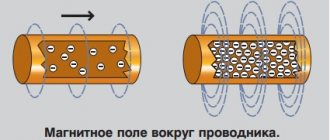
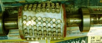
The essence of the method is as follows. It is known that in a three-phase asynchronous electric motor, the stator windings, due to the phase shift between them, excite a magnetic field rotating at the frequency of the electrical network fc (or a multiple of it). This field induces a current in the short-circuited rotor rods, which causes the rotor to rotate. The rotor speed of an asynchronous electric motor fвp in motor mode is slightly less than the rotation speed of the stator magnetic field. The frequency difference fc-fвp is the frequency of rotor slip relative to the stator field, and the ratio (fc-fвp)/fc is the slip value s, which is expressed in fractions of a unit or as a percentage. The magnetic field in the air gap of an asynchronous motor does not change strictly according to a sinusoidal law, therefore, when expanding the current signal into a Fourier series, harmonics are detected in it, having a frequency different from the frequency of the supply network. The presence of these harmonics is mainly due to the design features of the engine. According to (Geller B., Gamata V. Higher harmonics in asynchronous machines / Translated from English. Edited by Z.G. Kaganov. - M.: "Energy", 1981. - 352 pp., ill.) sources of temporary harmonics magnetic field in the air gap, which carry information about slipping, are the rotor gearing and the discrete arrangement of rods along the rotor winding. The harmonics from these sources (hereinafter referred to as tooth harmonic rotor (HRH)) always exist in the magnetic field of the air gap, so they are suitable for determining slip. In the proposed method, the determination of the rotor slip of an asynchronous electric motor is carried out by recording the instantaneous value of the current consumed by the electric motor J(t) in time using a current sensor installed on one of the phases of the power cable of the electric motor, and subsequent processing of the current signal. The recorded current signal J(t), in addition to the fundamental harmonic, also contains harmonics caused by the GGR. Their frequencies depend on the engine parameters and can be determined by the following expression:
Measurement methods
There are several ways to measure the slip of an induction motor. If the rotation speed differs significantly from synchronous, then it can be measured using a tachometer or tachogenerator connected to the EM shaft.
The measurement option using the stroboscopic method using a neon lamp is suitable for slip values of no more than 5%. To do this, a special line is either marked with chalk on the motor shaft, or a special stroboscopic disk is installed. They are illuminated with a neon lamp, and the rotation is counted for a certain time, then calculations are made using special formulas. It is also possible to use a full-fledged strobe, similar to the one shown below.
Mechanical characteristics of asynchronous motors
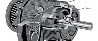
Induction motors are the main motors that are most widely used in both industry and agro-industrial production. They have significant advantages over other types of engines: they are easy to operate, reliable and low cost.
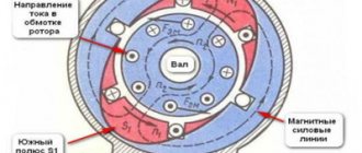
In a three-phase asynchronous motor, when the stator winding is connected to a three-phase alternating voltage network, a rotating magnetic field is created, which, crossing the conductors of the rotor winding, induces an emf in them, under the influence of which current and magnetic flux appear in the rotor. The interaction of the magnetic fluxes of the stator and rotor creates the torque of the motor. The appearance of EMF, and therefore torque, in the rotor winding is possible only if there is a difference between the rotation speeds of the magnetic field of the stator and rotor. This difference in speed is called slip.
The slip of an induction motor is a measure of how much the rotor lags behind the rotating magnetic field of the stator. It is designated by the letter S
and is determined by the formula
,
(2.17)
where w is the angular speed of rotation of the stator magnetic field (synchronous angular speed of the motor); w is the angular velocity of the rotor; ν – engine rotation speed in relative units.
The rotation speed of the stator magnetic field depends on the frequency of the supply network f
and the number of pole pairs
p
of the motor:
.
(2.18)
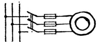
The equation for the mechanical characteristics of an asynchronous motor can be derived based on the simplified equivalent circuit shown in Fig. 2.11. The following designations are used in the equivalent circuit: Uф
— primary phase voltage;
I1
- phase current in the stator windings;
I2
– reduced current in the rotor windings;
X1
– stator winding reactance;
R1
,
R 1 2
– active resistances in the windings of the stator and reduced rotor, respectively;
X2 ΄
- reduced reactance in the rotor windings;
R
,
X
- active and reactive resistance of the magnetization circuit;
S
– slip.
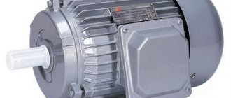
What it is
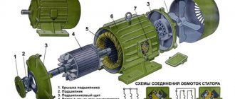
The operating principle of a 3-phase electric motor (asynchronous) is quite simple. Power is supplied to the stator winding. As a result, a magnetic flux is formed, shifted by one hundred and twenty degrees in phases. The overall flow will rotate.
The winding is a closed circuit in which an electromotive force arises. The magnetic flux rotates the rotor in the direction of the stator flux. A rotating electromagnet strives to equalize the rotating speeds of the stator and rotor fields.
The value showing the difference in the speed of rotation of the stator and rotor fields is slip. Since in an asynchronous electric motor the rotor always spins slower than the stator, the value usually does not exceed one. It is measured in percentages or units.
Calculated using the following formula:
Here n1 is the stator speed, n2 is the rotor speed.
Slip is one of the main parameters that reflects the correct functioning of an asynchronous electric motor.
Characteristics of an asynchronous electric motor, sliding torque.
Sliding torque, characteristics of three-phase asynchronous electric motor
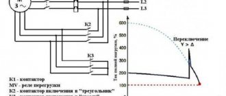
The slip torque curve for an induction motor gives information about the variation of torque with slip. Slip is defined as the ratio of the difference between the synchronous speed and the actual rotor speed to the synchronous speed of the device.
A change in slip can be achieved along with a change in speed; when the speed changes, the slip will change, and the torque corresponding to that speed will also change. The curve can be described in three operating modes:
Motor mode
There is a feed to the stator area, and the motor always rotates slower than synchronous speed. The torque of an induction motor varies from zero to full load torque, as does slip.
Slip undergoes changes from zero to one. When there is no load, the slip is zero, and when at rest it is equal to one. The curve shows that torque is directly proportional to slip. This means that the greater the slip, the greater the torque produced, and vice versa. Linear relationships greatly simplify the calculation of motor parameters.
Great Encyclopedia of Oil and Gas
Slip - asynchronous motor
What expression determines the slip of an asynchronous motor. [16]
Within certain limits, the slip of an induction motor is approximately proportional to the load torque on its shaft. From the vector diagram it can be seen that then the stator current /i also increases, and the phase shift cpi of this current relative to the network voltage decreases. [17]
Within certain limits, the slip of an induction motor is approximately proportional to the load torque on its shaft. [19]
In normal modes, the slip of an asynchronous motor has a small positive value, therefore the equivalent, active resistance Rpo. Js in the rotor circuit is significantly greater than the actual active resistance of the rotor Rpor - Additional active resistance rot ( 1 - s) / s is shown in Fig. 3 - 2 separately. [20]
Thus, the slip of an asynchronous motor is numerically equal to the ratio of losses in the rotor winding PM2 to the electromagnetic power Rem developed by the motor. [21]
The rotation and sliding torque of asynchronous motors depends on the voltage at their terminals. If the voltage decreases by at least 10% compared to the nominal value, the performance of production mechanisms driven by motors may slightly decrease. If the voltage drops significantly, the motors may stop. An increase in voltage at the motor terminals leads to an increase in their reactive power consumption. If the voltage at the motor terminals decreases with the same power consumption, its current increases. In this case, more intense heating of the motor insulation occurs and, accordingly, its service life decreases. Calculations show that during long-term operation of a fully loaded engine there are deviations in the voltage at the terminals. V-10% its service life is reduced by approximately half. [22]
Within certain limits, the slip of an induction motor is approximately proportional to the load torque on its shaft. [24]
Within certain limits, the slip of an induction motor is approximately proportional to the load torque on its shaft. From the vector diagram it can be seen that then the stator current 1g also increases, and the phase shift pg of this current relative to the network voltage U1 decreases. [25]
This increase is explained by an increase in slip of asynchronous motors due to a decrease in network voltage. [27]
Based on the principle of using the sliding energy of an asynchronous motor, cascades are divided into two groups: electromechanical and electrical. The first include cascades in which the sliding energy, using an electric machine or static converter, is supplied to an additional electric machine connected by a shaft to an asynchronous motor. The cascades of this group have an electrical connection of the rotor rings of an asynchronous motor through a converter with the armature of an additional machine, as well as a mechanical connection of the latter with the main drive motor. In electrical cascades, the sliding energy of an asynchronous motor is transferred to an alternating current network through an electric machine or static converter. The cascades of this group have only an electrical connection between the rotor rings of the asynchronous motor and the converter. The electromechanical cascade is characterized by the fact that the torque on the shaft of the production mechanism is created jointly by an asynchronous motor and an additional DC machine, while in an electric cascade this torque is created only by the main asynchronous motor. [28]
The stroboscopic method is useful for determining the slip of induction motors with respect to synchronous speed. When determining slip, instead of using a special disk, it is enough to evenly apply a series of chalk stripes to the surface of the coupling parallel to the axis, according to the number of engine gulles. [thirty]