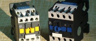
Electric motors of small and medium power installed in electrical installations and connected to power electrical networks must be turned on from a magnetic starter. Without this device, not a single machine will turn on. Let's look at what a magnetic starter is, its operating principle and connection diagrams.
Magnetic starter brand PM Source mkelektro.rf
Principle of operation
The main area of application of this device is production. Although they are also installed in everyday life if the owner of a private house has organized a small workshop for himself.
The rules for installing starters are varied. For example, it can be mounted in the machine panel itself, or it can be moved outside of it, in which case it is installed in a distribution panel. The latter are installed in panel rooms. The buttons that control the device are moved outside the boards to any required location. That is, the control itself is performed remotely.
The purpose of an electrical network element is to turn on or otherwise close and open the power supply network. The thing is that other devices of this type, namely switches or circuit breakers, cannot be used in electrical installations, because the latter, when turned on, consume a large starting current, three times the rated current. That is why the starter is connected to the network, because it can withstand these currents.
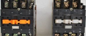
From a purely structural point of view, a magnetic starter is a simple device. It has two types of contacts: moving and fixed. The former are so called because they move with the armature, which moves under the influence of the magnetic floor towards the core when electric current is applied to the latter. The core is located in the coil, and it is itself energized by its own separate circuit to create a magnetic field. It is created precisely inside the coil.
Magnetic starter device Source infourok.ru
Essentially, the operating principle of a magnetic starter is as follows:
- clicked the “Start” button;
- power is supplied to the core and to the moving contacts;
- the core draws the armature into itself;
- he pulls the moving contacts behind him;
- the latter are pressed against the fixed contacts.
If it is necessary to de-energize the electrical installation, the “Stop” button is pressed. It cuts off the power supply to the core. The magnetic field disappears, the armature goes back to its original position, pulling the moving contacts behind it. A gap is formed between the two contact pairs. That is, the supply circuit is interrupted.
It should be noted that the magnetic device itself is not a so-called independent device in terms of functionality. For example, an RCD is such an element of the supply network. The starter is part of the electrical network, which includes this element itself, as well as paired control buttons. Without the latter, it will not work.
Control buttons "Start" and "Stop" Source opt-1362940.ssl
At the same time, it is necessary to highlight the fact that the magnetic starter is a kind of protection of the electric motor from overheating, because it has a thermal relay installed. And if the electric motor starts to operate under heavy load, that is, it starts to overheat, the starter will immediately turn it off automatically.
This device has one more important factor in terms of its installation in the power supply network. Since it is a switching device, that is, powered by buttons, there is no chance that it will turn on spontaneously. For example, if for some reason the mains voltage disappears, any machine will turn off. If there was a regular switch in place of the starter, then the machine would turn on itself if electricity were supplied to the machine again.
Imagine if one of the workers suddenly decided to carry out a small repair of the equipment without turning off the switch. There could have been serious injury. This cannot happen with magnetic starters. Because if you don’t press the “Start” button, the machine will not turn on.
Separate classification
Magnetic starters differ in type of purpose. There are modifications for weak, medium and strong inductive loads. Models for asynchronous AC motors are produced separately.
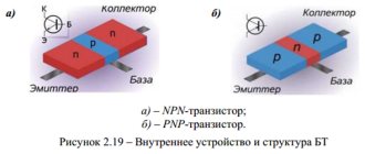
Asynchronous electric motor
Interesting! Modifications for a reverse network are considered common.
Push-button station on the device body
Push-button stations are necessary for remote control of equipment; the devices differ in functionality. When selecting equipment, performance characteristics are taken into account. Often, push-button stations are used for electric motors. The operator can be located remotely from the equipment.
You may be interested in this Features of conductive varnish
Push-button posts
In industry, installations are installed on cranes or rolling stock. It is also allowed to control fans or hydraulic pumps. At the workplace, you can create a whole complex of equipment with one control panel. The main task is to turn electrical equipment on and off in a timely manner. The drive class and starter type are taken into account.
If you look at the market, push-button posts are produced with an open, closed body, so security is taken into account. When selecting, the voltage level is taken into account. If we consider high-voltage equipment, a push-button station is required to operate in a DC circuit. Most posts are capable of influencing the switch.
Example! If you connect it to an asynchronous motor, you can control the speed. The same can be said about reverse. In this case, the operator’s work is again facilitated. At the machine, he is able to change the engine speed forward, backward, and select the desired mode.
The motor can be connected directly or through a magnetic starter. The controller stops via a button. One-button and two-button posts with the symbols “start” and “stop” are considered common. Simple modifications such as a lathe are made with one button. Elements for adjusting crane beams are included in a separate category. Their pusher buttons are protected and differ in the number of contacts.
Controller
The elements used are built-in springs and a set of special clamps. This is necessary to return the contact to its original position. Magnetic starters are connected directly to the posts. If we consider models with open cases, they are considered less secure and not safe to use; they have a limited scope of application.
Additional blocking and signaling contacts
There are magnetic starters with closing and disconnecting groups. Plus, there are modifications with built-in contacts, they come with stands. If you look at the circuit diagram, electrical interlocking is used.
Modifications with built-in contacts
Coil current and voltage
The average current parameter for starters is 15 milliamps, and the resistance reaches 15 Ohms. Significant changes in coil voltage are considered critical. If we consider the rheostat, the resistance reaches 160 Ohms. When evaluating elements, the residual current indicator, which depends on frequency, is taken into account. With a voltage stabilizer this parameter is significantly lower.
If it is necessary to calculate the operating current of the coil, the cable length and voltage are taken into account. Direct current is connected to the control unit. High operating current coils are susceptible to changes in inductance as well as resistance. Items are supplied with armatures, so contactor testing is required. There are modifications on the market with insulators that protect the current-carrying part.
Modifications with insulators
When the engine starts, the rated voltage increases. Coils can burn out if the inrush current increases. There is a small gap in the open contacts, but full resistance occurs when the magnetic circuit is lowered.
You might be interested in Electric meter Mercury 201
The presence of a thermal relay in the circuit
A relay is called a device that is sensitive to temperature or heat flow. There are mechanical and electrical modifications in the circuit. Optical devices that operate on the principle of linear expansion are considered modern. If you disassemble the elements, the nodes consist of two rods. There are models with and without extensions.
Bimetallic relays with a high refractive index are placed in a separate category. Movable contacts are used inside the device and there is a plate. They also use a closed-type electrical circuit. The material used is not only steel, copper, but also brass. The plates can be with or without a spiral, much depends on the level of expansion.
Important! Using special instruments, the amplitude of the change is determined. When the contacts are stationary, the circuit can be controlled.
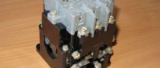
Magnetic starter - device and design features
So, contacts were discussed above. Let us add that there are usually either three or four pairs. This block is located inside a plastic case. Insulating cross-beams are located here. The device cover is installed on top. And, of course, inside there is an electromagnetic circuit consisting of a coil, a core and an armature.
There is one more element in this circuit that is not powered by anything. This is a spring. Its purpose is to quickly disconnect the contacts when the current stops flowing to the coil. It is against the spring that the core rests. The thing is that when the contacts open, an electric arc is formed between them. It negatively affects the material from which the contacts are made. That is, the arc will reduce the service life of the latter, and, accordingly, the entire device. Therefore, the faster the opening occurs, the better.
In addition to power contacts, the starter also contains so-called blocking elements. Their purpose is to block any launch actions if the latter is carried out incorrectly.
Note that today manufacturers produce devices of this type in different versions. The most common is with open contacts. In this form there are two modifications, designated as PME and PAE.
Magnetic starter brand PME Source i.simpalsmedia.com
The first ones are installed on electric motors with a power ranging from 0.27-10 kW. The second are 4-75 kW. Both modifications are used in networks with voltages of 220 and 380 V.
As for purely structural design, magnetic starters come in four types:
- open;
- closed, they are also protected or dust-proof;
- dust-splashproof;
- dust and waterproof.
Another difference between PME and PAE is that the former has one two-phase type relay - TRN. In the second, several such relays are installed. Their number depends on the size of the device itself.
Water-dust-proof starter in a casing with buttons Source multiscreensite.com
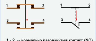
Contact block or contact attachment
Magnetic starter PML
This component, like the starter itself, contains a moving set of contacts: four normally open and four normally closed. Contacts are combined into pairs. Normal closed and open means that these contacts are normally in a certain position (closed or open); In this case, electric current can flow through closed contacts, but not through open ones.
To stop the flow of current through a normally closed contact, it must be opened; to ensure the flow of current through a normally open contact, it must be closed. When installing the attachment system and the starter itself (the first is placed in the upper part of the second on skids with hooks, secured with a latch), they are tightly connected to each other and function as a single system. When you press the corresponding button, the contacts change their normal state to the opposite.
When the starter and contactor are de-energized, normally closed contacts will be closed, open contacts will be open. When power is applied to the coil, the core will pull the contactor elements and reverse their normal state. To remove the attachment, you need to lift the locking latch and move the unit to be dismantled in its direction.
Starter and contactor attachment
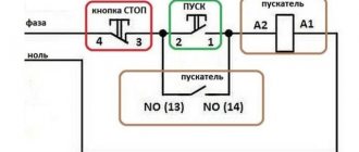
Connection diagrams
Let's move on to the important part of the topic - connecting the magnetic starter. Here it is necessary to consider two positions that differ from each other in the supply voltage: 220 or 380 volts.
Let us first consider the standard circuit, which is most often used in networks with a voltage of 380 volts. But we note the fact that the coils inside the device can have different voltages: from 12 to 380 volts. Therefore, the schemes may differ slightly.
For example, if the coil is 220 volts. The bottom photo is a wiring diagram for this type.
Magnetic starter connection diagram Source skad.com.ua
In this circuit, a starter with three power contacts and one blocking contact must be installed. It is optimal if a double “Start-Stop” button is installed. You can use two separate buttons, as in the photo and shown.
Pay attention to how the buttons are connected to the device itself - through a blocking contact. Therefore, it is impossible to make a mistake here. The main thing is not to confuse the contacts of the “Start” button with the contacts of the “Stop” button.
Now another question - how to connect a 380V starter with buttons and a 380 volt coil. This circuit is usually used when there is a need to organize protection against a situation where a phase failure may occur. Let us add that this is the simplest scheme. True, it is precisely this that helps protect only two phases. But this is better than being left without three at the same time in case of a break.
Essentially, everything will happen something like this. If one of the phases of the supply network disappears, the starter simply turns off the power supply to the electric motor. And this makes it possible to keep the motor in operating condition.
Connection diagram for a starter with a 380 volt coil Source amperof.ru
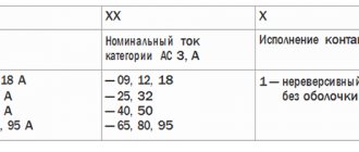
Mechanical and switching wear resistance
This characteristic shows the maximum number of on-off cycles - trips of the release. The more there are, the longer the service life will be.
This value is especially important for engines with frequent starts.
Mechanical wear resistance shows the number of on-off times in the absence of voltage. As a rule, the average mechanism can withstand about 10-20 million operations.
Electrical durability determines the permissible number of operation cycles and depends on the category of application. For example, if a contactor in AC-3 mode can withstand 1.7 million cycles, then in AC-4 it can withstand 200 thousand. As a rule, the manufacturer always indicates this characteristic in the technical data sheet.
Electrical wear resistance is divided into three classes:
- A - the highest, guarantees from 1.5 million to 4 million operations of the magnetic starter in operating mode;
- B - average, models of this class can withstand from 630 thousand to 1.5 million switchings;
- B - the lowest, the number of cycles from 100 thousand to 500 thousand.
Rules for installing a magnetic starter
If the device was installed incorrectly, there is a high probability that it will work with false alarms. Therefore, some useful tips:
- Do not install the starter in areas that are subject to vibration or shock loads.
- Installation is usually carried out in an electrical panel. But there are also rules here, the first of which is that the installation site must be flat, vertical and level.
- It should not be exposed to heat from any sources. This may cause the thermal relay to trip on its own.
- The switchboard cannot be installed in rooms where there is electrical equipment with a current higher than 150A. the whole point is that starting and stopping such equipment is accompanied by a shock.
- If one end of the wire is inserted into the contact clamp, then it must be bent in the shape of the letter “P”.
- If two ends of the wire are inserted into the clamp at once, then they are installed on both sides of the screw, and they must be straight, not bent.
- Before making the first start, the magnetic starter must be checked for technical condition and for correct connection of the contacts.
Installation is carried out in the switchboard Source tehnormal.by
What is the difference between magnetic starters and contactors?
Both devices are switching devices, that is, they control power networks. And more often they are installed in the electric motor starting system. In both devices, in addition to power contacts, there is at least one, and often more, which is used for the control circuit.
Otherwise they differ. Firstly, in size and weight. Starters are much more compact. At the same time, their weight is much less. For example, if you take both devices of the same rating in different hands, the contactor will be many times heavier. In addition, it should be noted that contactors that would be designed for low currents simply do not exist. They are replaced in power networks by starters.
Secondly, it's all about the design. Contactors are open type devices. They do not have a body or lid. Therefore, the installation and connection of contactors is carried out in special rooms, which must be locked with a key. Outsiders are prohibited from entering such premises. In addition, they are well protected from precipitation. The design of contactors contains arc-extinguishing chambers.
Contactor for power circuit Source dc-electro.ru
The latter are not included in the starters. But this variety is equipped with a sealed case closed with a lid. There are modifications located in metal casings. Therefore, the starters can be installed anywhere, even outdoors.
Thirdly, the magnetic starter has three pairs of power contacts in its design. Therefore, their main purpose is to control electric motors. Contactors are designed to control any type of electrical circuit. Therefore, the number of power contacts in them can vary in the range of 2-4.
There are no other differences.
Varieties and types
Rice.
3. Types of electromagnetic starters Depending on the design features and functions performed, electromagnetic starters are divided into several categories. We will consider the most relevant principles of separation by types and types.
By type of powered load:
- PML - used for three-phase electric motors with a squirrel-cage rotor or stove heating;
- PMA - used to connect asynchronous electrical machines;
- KMI - used to start a three-phase load, has similar characteristics to the first option, but significantly wider functionality;
- PME - used for reverse starting of asynchronous type electrical machines.
According to the rating at which power contacts can open and close, electromagnetic starters are divided into four categories:
- The first is for loads ranging from 10 to 16A;
- The second – powered load up to 25A;
- Third - for electrical machines with a rating of up to 40A;
- The fourth is for turning on and off three-phase motors at 63A.
In the same way, electromagnetic starters can be divided into categories 24V, 220V, 380V, 660V, etc. The voltage corresponds to the supply rating so that the actual value is no higher than that allowed for a particular switch.
Depending on the location, there are different categories of protection of the starter from the penetration of dust and moisture, which are marked with the letters IP and two numbers. In practice, the higher the numerical value, the higher the resistance to factors.
There are the following types:
- Open – for installation exclusively in cabinets, drawers, etc.;
- Protected - in rooms with a minimum amount of dust and a low probability of moisture penetration;
- Dust- and moisture-proof - can be mounted to open and close power circuits outdoors.
According to switching wear resistance, three categories are distinguished:
- A – the highest resistance of contacts to wear when connecting magnetic devices;
- B – average wear;
- B – low level of wear resistance.
Briefly about the main thing
Magnetic starter is a switching device for controlling a power network. Namely, starting and stopping electric motors.
Magnetic starter device: three pairs of power contacts, a coil with a core to which an armature is connected. The latter is connected to a block of moving contacts.
The starter is connected via the start-stop button.
Although the starter performs the functions of a power network contactor, it is not a contactor, because it is very different from the latter in its design form and current rating.
What is it used for?
This is a switching type device. It is needed to connect equipment to the network or de-energize it. It is designed to operate with voltages not exceeding 1000 V. This device can be used in the following cases:
- When the street lights are turned on.
- For controlling powerful asynchronous motors.
- Can be used to work with external or internal lighting of industrial facilities.
- When switching devices for warming up. An example is infrared heaters or heating elements.
- Application as starting equipment for industrial automation systems.
The need to select magnetic starters arises when installing the appropriate equipment or during its repair.
How to choose a starter is described in the video: