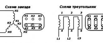
The essence of measurements
Insulation resistance refers to the ability of a material not to allow electric current to pass through itself. Each dielectric, depending on the place of use, has its own regulatory requirements. The frequency of inspection and the required values are indicated in the “Rules for the Construction of Electrical Installations” (PUE) and in the “Rules for the Technical Operation of Electrical Installations by Consumers” (PTEEP).
All types of tests can be divided into three groups:
- carried out by the manufacturer at the factory;
- performed directly on site after modernization or repairs;
- planned according to the requirements of safety rules and regulations.
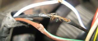
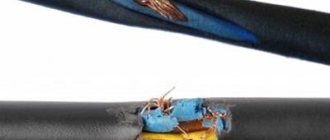
Possible damage, in addition to manufacturing defects, most often occurs due to operating conditions. This is the effect of overcurrents that cause overheating of the protective shell, the influence of chemical reagents, and mechanical ruptures caused by both installation errors and rodents. The purpose of measurements is to prevent electric shock to humans and ensure fire safety.
Damage to the insulation causes breakdown. This is a situation in which electrical contact occurs between two conductors isolated from each other. For example, between adjacent wires in a cable or when a person touches parts of an electrical installation. Usually, when a breakdown occurs, a hole is burned and a change in the color of the insulating material is observed. The mechanism of breakdown of a solid dielectric is based on an electronic avalanche-like process. It occurs due to the formation of a so-called plasma gas-discharge channel in the material.
Only a specialist who has a knowledge test certificate and an admission group of at least third is allowed to measure insulation if measurements are carried out in a network with a voltage of up to 1 kV, and not lower than fourth when measuring above 1 kV.
After completing the measurement of electrical insulation resistance, the results obtained are processed and a conclusion is drawn about the possibility of further operation of the network. Thus, the ambient temperature is of great importance for the reliability of the result. The normalization of measurements in the PUE is indicated for 20 °C, therefore, if work is performed at a different temperature, then the data obtained is recalculated using the formula: R=K*Riz, where K is the reduction coefficient specified in the additions to the PUE.
Devices used
The instruments used to carry out measurements are conventionally divided into two groups: panel meters and megohmmeters. The former are used with mobile or stationary electrical installations with a separate neutral. The typical design of switchboard insulation monitoring devices includes an indicator and relay part. These meters can operate in continuous mode and be used in 220 V or 380 V AC networks of different frequencies.
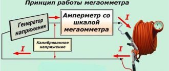
In most cases, measurements are carried out with a megger. Its difference from an ordinary ohmmeter is that it works with fairly high voltage values, which the device itself generates. There are two types of megohmmeters:
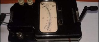
- Analog . To obtain the required voltage, they use a mechanical generator, which is a dynamo. This type is often called "pointer" due to the presence of a graduated scale and a dynamic head with a pointer. The measurement principle is based on the magnetoelectric effect. The greater the current flows through the coil, the more, in accordance with the law of electromagnetic induction, the needle deviates through a larger angle. The devices are of a simple type with good reliability. Today they are already morally obsolete, as they have significant mass and dimensions.
- Digital . The circuit of a modern device uses a powerful signal generator assembled on an integrated circuit (PWM controller) and field-effect transistors. Discrete megohmmeters, depending on their design, can operate from a network adapter or an independent power source, for example, a battery. The results are displayed on a liquid crystal display. The work is based on comparing the measured signal with a reference signal and processing the data in a special unit - an analyzer. The device is lightweight and small in size, but working with it requires certain qualifications.
The main parameter characterizing the operation of the meter is the error of the output result. In addition, its main technical parameters include: resistance limits, the amount of generated voltage, and temperature range.
Test method
In order to correctly measure insulation resistance, it is necessary to prepare both the test subject and the device itself. The room temperature should be within 25±10 °C with a relative humidity of no more than 80%. Before starting work, you should disconnect the object being measured from the power supply. Make sure that no work is being done on the disconnected line and no one is touching live parts. All fuses, lamps and similar electrical devices must be removed.
Before testing, the residual charge is removed from the disconnected live parts. This is done by connecting them to the ground bus. The contact jumper is removed only after connecting the meter. At the end of the test, the residual charge is again removed by briefly restoring the grounding.
The standard package of the megohmmeter includes three probes. The following are connected to them: protective grounding, line under test, screen. The latter is used to eliminate leakage currents.
The measurement technique can be presented as follows:
- In accordance with the requirements of the PUE for the line, the test voltage is selected. For example, for home wiring, the value is set from 100 V to 500 V. When working with a digital device, you need to press the “Test” button, and on an analog device, turn the knob until the indicator reports the appearance of the required voltage value.
- The linear terminal of the tester is connected to the cable core being tested, and the ground terminal is connected to the remaining wires combined into a bundle. That is, each core is checked in relation to other wires electrically connected to each other.
- Each core is tested relative to the ground, while the remaining wires are not connected to ground.
- If the data obtained turns out to be unsatisfactory, then measurements are carried out separately for each core in relation to all taken conductors in the cable.
- All obtained values are recorded and then compared with the standards of PUE and PTEEP.
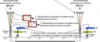
It should be noted that if for some reason it is not possible to disconnect the load in a low-voltage network before testing, then the phase and neutral conductors are measured only relative to PE (ground). In this case, the working zeros should be disconnected from the neutral bus. If this is not done, then the data obtained for any wire will be the same and equal to the resistance of the conductor with the worst parameters.
Procedure for checking cable insulation resistance with a megohmmeter
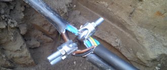
You come to the site and see, for example, the following picture.
Before directly checking the insulation resistance, you must make sure that:
- The cable cores are ringed and marked (read about ringing here)
- on the cable cores where we will supply voltage there is no dirt, scale, or paint (there is no such thing on the cable core, but it may be on the grounding, which is painted, or it may be covered with a layer of rust, then you need to scrape it off with a screwdriver or knife)
- at the other end of the cable no one is working and the cable is disconnected from the load and the power source (it is not worth applying voltage to the installer, who can cut the cable from the other side, or measuring the Rx of the cable with the load, it is also worth making sure that we do not apply high voltage to the secondary circuits and elements that can become unusable at 2500V, so sometimes they are simply switched to 500V)
- the cable is de-energized and measures are in place to prevent accidental supply of voltage to the cable under test (locks, posters, cells removed)
- if the vigilante test (measurement of insulation resistance) is combined with high-voltage tests, then you need to make sure that there is a person at the second end of the cable (the second end is opposite from the test site) or the room is locked and fenced with posters posted
- The megohmmeter is in good condition and suitable for use (verification mark on the body and the ends of the device are tested)
- you have the right and qualifications to work with a megohmmeter and perform this type of work (group 3 on electrical safety and an unexpired test of special knowledge, plus a medical examination)
- the megohmmeter wires must have high insulation (here you can also do the following: connect the two megohmmeter wires and apply voltage - the value should be zero, since there is no insulation between the wires, and if you separate them, then infinity - since the air resistance is high)
Once the above points have clearly been implemented, you can get down to business. Let's play together!
Valid values
The minimum reading of the measured voltages must be higher than the standardized values. The required resistance value is set by the manufacturer of cable or electrical products, in accordance with the current technical specifications.
Manufactured electrical products are divided into several types and are: general use, power, control and distribution. Products are divided among themselves not only by physical characteristics, but also by design. Their diversity is determined by the environment in which they are used. For example, a cable intended for laying in the ground is reinforced with metal tape and consists of several layers of insulation.
Insulation resistance is measured in Ohms. But due to the large values of the indicator, the prefix mega is always used. The number given is usually calculated for a specific length, most often a kilometer. If the length is less, then a recalculation is simply performed.
For cables used in communications and transmitting low-frequency signals, the insulation resistance must be at least 5 thousand MOhm/km. But for main lines - above 10 thousand MOhm/km. But at the same time, the minimum required value is always indicated in the product passport.
In general, the following insulation resistance standards are accepted:
- cable laid in a room with normal environmental conditions - 0.50 MOhm;
- electric stoves not intended for transportation - 1 MOhm;
- electrical panels containing distribution parts and main wires - 1 MOhm;
- products supplied with voltage up to 50 V - 0.3 MOhm;
- electric motors and other devices operating at a voltage of 100-380 volts - 0.5 MOhm;
- devices connected to an electrical line designed to transmit a signal with an amplitude of up to 1 kV - 1 MOhm.
For cables connected to power lines, a slightly different standard applies. Thus, wires used in an electrical network with a voltage of more than 1 kV must have a resistance value of at least 10 MOhm. For the rest, except for the control ones, the minimum threshold is halved. For control wires, the standard requires a resistance value of at least 1 MOhm.
Who takes the measurements
To carry out measurements, electricians and other specialists who have permission to work with electrical communications and electrical equipment are involved.
If we are talking about periodic inspections in an organization, then a special commission is created to monitor electrical insulation, which includes an employee of the enterprise and a specialist from the installation or maintenance company.
The commission must include at least two people, but if necessary, its composition can be expanded to include outside experts.
The task of the commission is to check the condition of the cable and measure the resistance of the insulating coating, and then enter all the indicators into the report.
Insulation control
Insulation resistance is an important parameter of electrical products. The safety of work depends on the parameter being within the established standards. Therefore, it is important to periodically measure the value, identifying deviations in time. In addition, industrial facilities require mandatory frequency of measurements.
In accordance with established standards and regulations, insulation measurements must be carried out:
- for mobile or portable installations at least once every six months;
- for external devices and outdoor cables, as well as in high-risk areas - at least once a year;
- for all other cases at least once every three years.
That is, in premises, for example, such as an office, a store, a school, resistance measurements should be performed at least once every 36 months. After completion of the tests, a report must be drawn up indicating the measured data. If the measurements are unsatisfactory, then the electrical section is taken out for repairs until it is brought to the required standards.
What is meant by "isolation"
Any electrical cable must be specially insulated. The insulating coating allows you to separate the wires through which current flows, as well as disconnect these wires from the ground.
In order to assess how well such insulation “works”, its resistance is measured - their results are the main value in the work of electrical specialists.
The first measurement is carried out at the cable manufacturer, then during installation and subsequently during the entire period of use of the cable product. This is due to the fact that insulation is influenced by factors such as weather, period of its use, quantity, frequency of damage on the line, etc.
Safety requirements
One of the fundamental rules when examining insulation is that you cannot begin work without making sure that there is no voltage in the area being measured. The device used for testing must be certified or at least certified.
It is necessary to use only a megohmmeter whose output voltage meets the established standards. So, for networks or equipment with voltages up to 50 V, a tester is used that produces 100 V. Using a device with a lower value will not provide truthful information about the condition of the area, and a larger one can lead to damage.
Measuring resistance with a megohmmeter must be performed only on disconnected live parts, with the mandatory removal of residual charge. In this case, the grounding from the conductive parts is removed only after connecting the tester. The connecting wires are connected using insulating rods. When working, touching live parts, even with dielectric gloves, is prohibited.
Test methods used
Even before checking the condition of the insulation, it is important to decide on the object where you want to evaluate its quality. It can be:
- Electrical wiring.
- High voltage power cables.
- Low voltage power lines.
- Control wires.
For each of these electrical categories, individual methods for measuring insulation resistance are selected. Let's consider all the listed options in more detail.
Wiring
Before starting measurement procedures, electrical wiring and distribution boxes are inspected for breaks and obvious damage. After this, the places where the wires are connected to standard sockets and switches are examined.
Important! It is allowed to begin measuring insulation resistance only after the wiring is completely de-energized and all consumers at the facility are disconnected from it.
Measuring the insulation resistance of electrical wiring using a digital device Fluke-1507
In a single-phase network, to determine the required parameter, you will need to carry out the following operations:
- First, the megohmmeter probes are connected between the phase and neutral conductors of the wiring.
- Then the insulation resistance between the phase and central conductor of the protective grounding is determined.
- The number of measurements taken corresponds to the set of wires in the line.
If, when taking readings, the megohmmeter shows a resistance of less than 0.5 Mohm, the electrical line will have to be divided into shorter segments. Based on the results of subsequent inspections of each of them, there is an area with unsatisfactory insulation quality. It will subsequently need to be completely replaced.
High voltage power cables (preparation)
Before measuring the insulation of a power cable, the latter is checked to ensure that there are no dangerous voltages on it. In addition, to prepare the measuring circuit, you will need to perform the following operations:
- First of all, the residual charge must be removed from the current-carrying conductors using portable grounding.
- Then the cable is completely cleaned of dust and dirt that interfere with the measurement process.
- After this, you will need to familiarize yourself with the cable’s passport data (the required parameter obtained from the results of factory tests is indicated there).
- The last operation is necessary in order to determine in advance the operating limit set on the device.
Preparing a cable line for insulation resistance measurements
Important! Before measuring the cable insulation resistance, it is necessary to carry out a control check of the megohmmeter for serviceability.
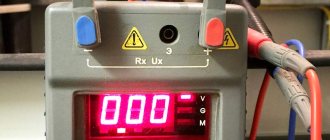
This operation consists of monitoring the readings on the instrument scale with the measuring ends closed and open. In the first case, the arrow moves closer to “zero”, and in the second case it shows “infinity”.
Power cables (measurements)
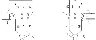
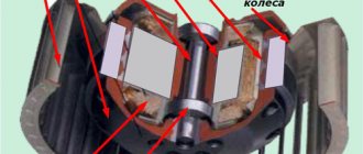
Measuring insulation resistance with a megohmmeter begins with a control check of each phase in relation to a grounded steel shell. And only after this the resistance between the individual cores is checked (photo on the left). In the process of taking readings, it is unacceptable for the measuring ends to come into contact with each other, as well as to come into contact with grounding structures and the steel shell.
a) the insulation resistance between the phase and the grounded sheath of the cable is measured, b) the resistance between the phases of the cable line is measured, respectively, “A” - “B”, “B” - “C” and “A” - “C”.
If it is found that the insulation resistance is below the permissible level, additional measurements are carried out in accordance with the requirements of the Electrical Installation Regulations. They involve measuring the insulation of all phases in relation to the ground and estimating the conductivity between phase conductors.
Please note: To improve the accuracy of readings indicating the value of wire insulation resistance, several measurements are taken.
Their total number varies: for a 3-core cable within 3-6 measurements, and for a five-core cable it may require 4, 8 or even 10 approaches. Since there are several measurement schemes for three-phase circuits, you should familiarize yourself with the option proposed by the manufacturer using the same passport. According to the instructions, no more than 60 seconds should pass until accurate readings are indicated on the megohmmeter scale (from the moment the ends are connected and high voltage is applied). If during this time, due to high humidity, for example, it was not possible to determine the readings (the needle did not deviate by the calculated value), the operation will have to be performed again.
Before retesting, the residual charge must be removed again by applying grounding. Then you will need to switch the device to the desired limit and repeat the control measurements. According to safety regulations, this operation must be carried out with dielectric gloves. It is recommended to follow the instructions in pp. 1.7.81, 2.1.35 PUE, which stipulate safe work conditions. The main ones are given below.
- for zero operating and protective busbars, the insulation must be equivalent to the protective coating of phase conductors;
- on the side of the supply voltage sources and its receiver, the neutral conductors should be disconnected from the grounded elements of the circuit;
- Measurements in power electrical wiring are carried out only when the voltage is completely removed and the input circuit breakers or switches are turned off.
The last point is supplemented by the mandatory requirement to remove the fuses, turn off all existing receivers and unscrew the light bulbs. The measurement schemes proposed in the instructions differ only in their number (4 and 8 instead of 3 and 6) and the need to use the “Screen” protective terminal on the megohmmeter.
Low voltage power cables
When working with low-voltage power lines, they are first checked to ensure that there are no dangerous voltages on their elements. Similar to the high-voltage cables already discussed, before examining these products, you will need to perform the following operations:
- First, a dangerous residual charge is removed from the current-carrying conductors using portable grounding.
- Upon completion of this operation, the cable sheath and its working cores are completely cleaned of dust and dirt.
- Then the documents (passport, for example) are studied, which indicate the standardized insulation resistance for the test sample.
- The last operation is carried out with the aim of approximate estimation of the measured value and selection of the desired measurement limit on the device.
To carry it out, take a megohmmeter designed for a generation voltage of 1000 Volts. Upon completion of all preparatory operations, proceed directly to measurements. Their order can be represented as the following sequence of actions:
- First, the required resistance is measured between the phase conductors of the cable line under test (“A” - “B”, “B” - “C” and “A” - “C”).
- Then, the insulation state of each phase relative to the neutral wire (N) is assessed in turn.
- The following is a sequence of measurements between each phase and the PE ground wire (carried out when checking a three-phase five-core conductor).
- To carry out the last operation, the neutral wire is disconnected from the grounding bus, after which the resistance between the N and PE conductors is measured.
Upon completion of each next action, it is necessary to “remove” the residual charge in the manner already described.
Control cables (preparation)
In this case, it will be possible to check the resistance only if the following requirements are met:
- The ambient temperature should be within the range from –30 to +50 degrees (with humidity up to 90%).
- They influence the admissibility of working with a particular type of megohmmeter in a particular situation.
- The measurement conditions (the length of the monitored cable, in particular) and the operating voltage are selected depending on its brand.
- If there is no passport for the cable product, a test voltage of 0.5 to 1 kV is applied to it according to the PUE (Table 1.8.39).
Please note: It is allowed to carry out tests together with all equipment connected to the cable (magnetic starters and protective relays installed in the line).
Before testing resistance, be sure to be familiar with safe cable handling techniques. They boil down to compliance with the following rules:
- Only specialists with the 3rd tolerance group or higher are allowed to take measurements under voltages up to 1 kV;
- the cable under test must be disconnected from the power supply, after which the residual charge is removed from it;
- Before starting measuring operations, you must ensure that there are no unauthorized persons near this place.
Voltage is applied to the current-carrying conductors using probes with insulated handles of the “holder” type. In addition, for safety reasons, it is prohibited to touch the conductive busbars to which the turned on megohmmeter is connected. Upon completion of the current tests, the residual charge must be removed from the control part of the cable. To do this, portable ground connections are used or a special function of the measuring device is activated (available in some models).
Control cables (work order)
The procedure for testing the insulation protection of control cables is similar to the provisions developed for low-voltage wiring lines (up to 1 kV). An exception is the clause on disconnecting current-carrying conductors from load equipment. Due to the small magnitude of the transmitted signal, this is not necessary in this situation.
To carry out the tests, you will need a digital or analog megohmmeter, according to the passport, designed for operating voltages from 0.5 to 2.5 kV. The order of measurements in this case looks like this:
- First, on the side of the cable being tested, the leads of the current-carrying conductors are carefully cut and cleaned, and then separated from each other to some distance (about 5-10 cm).
- Next, each wire is connected in turn to the “+” of the megohmmeter, and all other wires are twisted and connected to the “ground”.
- The second input (“–”) of the device is also connected there (see figure below).
- Test voltage is then applied to the working cable.
- When using modern digital devices, an external power source (electrical network or battery) will be required.
- The tests last for at least a minute, after which the result is recorded on a scale and then entered into the logbook.
- Further, all the described operations are performed with each signal core separately (it is connected to the device, and all others are twisted and connected to the second contact, which in turn is connected to the ground.
At the end of the measurements, the residual charge is removed from the working conductors, and the megohmmeter is allowed to “settle” until the next series of tests. The duration of the pause allocated for this depends on the specific type and brand of the device. The following measurements are carried out taking into account the frequency of the insulation test.