When working with electrical networks, measuring instruments play an important role in ensuring the safety of operating personnel, as well as in monitoring the condition of electrical appliances and their connection diagrams. The same applies to a device called a megohmmeter (formerly “megohmmeter”), designed to measure resistances that have very high values. This publication contains information about what a megohmmeter is, its scope of application, and how to use it. In this article we will talk about measuring resistance with a megohmmeter and look at step-by-step instructions.
Appearance of a device with a manually operated dynamo
Purpose of the device, design, principle of operation
The name of the device speaks for itself: “mega” means 106 or 1 million, “ohmmeter” means resistance measurement. Thus, it becomes clear that resistance measurements of millions of ohms or thousands of kohms are available with the device. Where and who might need such indicators? Basically, this is insulation and everything connected with it, that is, means that exclude the action of electric current where it is not necessary according to the electrical circuit or is unacceptable from a safety point of view.
Cables transmitting electricity, output transformer insulators, windings of electric motors of devices, machines and mechanisms must have reliable insulation that can prevent contact of conductors with each other, as well as with the device body, and prevent short circuits or electric shock to a person. Accordingly, the resistance value of the insulating means must be sufficiently high. A megohmmeter is designed to measure it. It can be used to determine that equipment needs to be replaced, repaired, or temporarily removed from work and dried out.
Device overview
The F4103-M1 meter checks the contour of any geometric shapes and sizes. The appearance of the device is shown in the photo:
Technical characteristics are shown in the table:
Next in our review is the M416 direct reading meter for determining active resistance. The device is time-tested, has high accuracy and stability. This is what it looks like:
Basic technical data:
Carrying out measuring work using m416 is shown in the video:
https://youtube.com/watch?v=BheNKsdRl_4
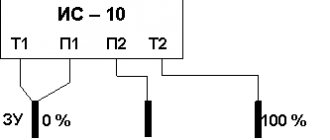
The modern microprocessor measuring device IS-10 is next in our review. LCD display, automatic measurement range, built-in memory of the last forty measurements. Impact-resistant housing with IP42 protection. You can see the appearance in the photo below:
The device is designed for measuring and testing grounding elements using the two-, three-, and four-wire method. It can also be used to check the quality of the connection of ground bus conductors, etc.
The operating instructions for the more advanced IS-20/1 meter are shown in the video:
Well, our list of devices for measuring ground loop resistance ends with the professional device MRU-101. The device can measure soil resistivity and adapt to a specific task through analysis and data collection. MRU-101 has a memory for the last four hundred measurements. Appearance of the meter:
Main technical characteristics of this device:
Video review of MRU-101:
Internal structure of the measuring device
The main components of the device are:
- voltage generator (DC);
- measuring unit showing readings;
- measurement range switch (kOhm-MOhm), which makes it possible to change the output voltage by turning on various built-in resistor circuits;
- resistors are resistances that limit the flow of current.
An approximate diagram of the device of a megohmmeter with the designation of its main parts.
The internal generator in old-style devices operates from a manual drive due to the dynamo of the machine. Modern devices operate on batteries. Pointer (analog) devices display readings on a scale using two frames: one - working and the second - counteracting. The measuring unit of electronic megaohmmeters displays values on the display in digital form.
Appearance of a digital electronic megohmmeter for insulation diagnostics
Terminals for connecting probes, instead of being marked “L” and “Z”, may be marked “Rx” and “-”.
How to measure correctly
Before taking measurements, it is necessary to reduce the number of factors affecting the accuracy of the final results. For analog instruments with a dial indicator, this is, first of all, a horizontal arrangement of the housing. The magnitude of the error is also affected by the proximity of electromagnetic fields, so the devices should be placed as far as possible from them. This requirement must be observed for all types of meters.
Before testing, you should always calibrate the device. On induction, this can be done by turning the slider handle. Some electronic devices have a self-test function, so they will automatically fine-tune the operating conditions. A four-wire test circuit gives accurate results.
Operating principle of the device
The operation of the device is based on Ohm's law, known from a school physics course, where the current strength is directly dependent on voltage and resistance, which is reflected by the formula I = U/R.
The voltage is generated by the device itself. The measuring unit, in fact, is an ammeter that records the value of the current flowing through the circuit, but since the voltage supplied by the generator is known in advance, the divisions of the measurement scale are calculated and marked for kilo- and mega-ohms.
The insulation resistance test is carried out when the power is turned off, but the high voltage generated by the device can accumulate (for example, on capacitors) and collect into dangerous charges that can lead to electric shock to a person.
Review of megaohmmeter models and their manufacturers
The modern measuring equipment market offers a wide selection of devices from different brands. Through online stores you can purchase analog and digital megohmmeters in electrodynamic and electronic versions. Different models designed for making measurements in different ranges differ not only in operating parameters, but also in dimensions and price values. It is impossible to cover all models and their manufacturers in one publication, therefore, for orientation in the variety of products and their prices, domestic and foreign products are given as an example:
| A country | Device name | Model | price, rub. |
| Russia | ProfKip ES202/1g | Electrodynamic | 8 000 |
| Belarus | E6-26 | Electronic digital | 71 000 |
| Ukraine | ES0210/3 | Electrodynamic | 14 000 |
| Poland | Sonel MIC-2505 | Electronic digital | 60 000 |
| China | Uni-T UT-513 | Electronic digital | 16 000 |
The given cost values are averaged and cannot serve as a basis for placing orders and drawing up estimates for purchases. When choosing a measuring device, you cannot focus only on its cost or compact size. It is necessary to take into account quality (brand name, certificate of conformity, warranty) and technical parameters.
Digital electronic megohmmeter with a range from 500 to 5000 Volts
For example, the MY-40 megaohmmeter from the Japanese company YOKOGAWA is capable of operating in 4 ranges: 125, 250, 500 and 1000 V; it can be used to measure the resistance of ordinary conductors and powerful cables; it automatically discharges after the measurement is completed. Moreover, its cost is about 32 thousand rubles.
Some devices operate in the voltage range from 500 to 10,000 Volts and have an automatic selection of measurement limits, for example, Standard Electric 6212 IN. Its cost is approximately 55 thousand rubles.
Of course, powerful and expensive measuring instruments are more in demand at specialized enterprises, but for use in everyday life and small service centers it is enough to purchase an inexpensive compact electronic or electrodynamic analog megohmmeter.
How to measure ground loop resistance - a review of techniques
08/15/2016 no
Grounding resistance must be measured to make sure that it matches the requirements of the PUE (electrical installation rules) Ch. 1.8. as well as PTEEP pr. 3.3.1. Measurements taken in an electrical installation with a solidly grounded neutral (the voltage of which is below 1000V) must comply with the following standards. It doesn’t matter whether in winter or summer, the value should not exceed 8, 4 and 2 Ohms at voltages of 220, 380, 660 V (for sources with three-phase current), respectively, or 127, 220 and 380 V for sources with single-phase current. For electrical installations where an insulated neutral is used (voltage below 1000V), the resistance of the grounding loop must correspond to clause 1.7.104 of the PUE and is calculated using the formula Rз * Iз < 50 V. Below we will consider the main methods for measuring the loop, as well as instruments that can be used for this .
Review of techniques
Ammeter-voltmeter method
To carry out measurement work, it is necessary to artificially assemble an electrical circuit in which current flows through the ground electrode under test and the current electrode (it is also called an auxiliary electrode). This circuit also uses a potential electrode, the purpose of which is to measure the voltage drop during the flow of electric current through the ground electrode. The potential electrode must be located equally far from the current electrode and the ground electrode being tested, in an area with zero potential.
To measure resistance using the ammeter-voltmeter method, you must use Ohm's law. So, using the formula R=U/I we find the resistance of the ground loop. This method is well suited for measurements in a private home. To obtain the required measuring current, you can use a welding transformer. Other types of transformers are also suitable, the secondary winding of which is not electrically connected to the primary.
Using special devices
Let us immediately note that even for measurements at home, a multifunctional multimeter is not very suitable. To measure the resistance of the ground loop with your own hands, use analog instruments:
Let's look at how to measure resistance with the M-416 device. First you need to make sure that the device has power. Let's check the presence of batteries. If they are not there, you need to take 3 batteries with a voltage of 1.5 V. As a result, we get 4.5 V. The device, ready for use, must be placed on a flat horizontal surface. Next, we calibrate the device. We put it in the “control” position and, holding the red button, set the arrow to the “zero” value. For measurements we will use a three-clamp circuit. We drive the auxiliary electrode and the probe rod at least half a meter into the ground. We connect the device wires to them according to the diagram.
The switch on the device is set to one of the “X1” positions. We hold down the button and turn the knob until the arrow on the dial is aligned with o. The result obtained must be multiplied by the previously selected multiplier. This will be the desired value.
The video clearly demonstrates how to measure grounding resistance with the device:
More modern digital instruments can also be used, which greatly simplify the measurement work, are more accurate and retain the latest measurement results. For example, these are devices of the MRU series - MRU200, MRU120, MRU105, etc.
Working with current clamps
Ground loop resistance can also be measured using current clamps. Their advantage is that there is no need to disconnect the grounding device and use auxiliary electrodes. Thus, they allow you to quickly monitor grounding. Let's consider the operating principle of current clamps. An alternating current flows through the grounding conductor (which in this case is the secondary winding) under the influence of the primary winding of the transformer, which is located in the measuring head of the clamp. To calculate the resistance value, it is necessary to divide the EMF value of the secondary winding by the current value measured by the clamp.
At home, you can use current clamps S.A 6412, S.A 6415 and S.A 6410. Learn more about how to use current clamps. you can in our article!
Application of ammeter and voltmeter
The method is as follows. On both sides of the grounding structure to be tested, at an equal distance (about 20 meters), two electrodes (main and additional) are placed, after which alternating current is supplied to them. An electric current begins to flow through the circuit thus formed, and its value is displayed on the ammeter display.
A voltmeter connected to the grounding device and the main ground will show the voltage level. To determine the total ground resistance, you need to use Ohm's law by dividing the voltage value shown by the voltmeter by the current value shown by the ammeter.
This measurement method is the simplest, but has a low level of accuracy, so other methods are most often used.
What is the frequency of measurements?
Visual inspection, measurements, and, if necessary, partial excavation of the soil must be carried out according to the schedule established at the enterprise, but at least once every 12 years. It turns out that when to take grounding measurements is up to you. If you live in a private house, then all responsibility lies with you, but it is not recommended to neglect checking and measuring resistance, since your safety directly depends on this when using electrical equipment.
When carrying out work, you must understand that in dry summer weather you can achieve the most realistic measurement results, since the soil is dry and the instruments will give the most accurate values of grounding resistance. On the contrary, if measurements are taken in autumn or spring in damp, humid weather, then the results will be somewhat distorted, since wet soil greatly affects the spread of current, which, in turn, gives greater conductivity.
If you want measurements of protective and working grounding to be carried out by specialists, then you need to contact a special electrical laboratory. Upon completion of the work, you will be given a grounding resistance measurement protocol. It displays the location of the work, the purpose of the ground electrode, the seasonal correction factor, and also at what distance the electrodes are located from each other. A sample protocol is provided below:
Finally, we recommend watching a video that shows how to measure the grounding resistance of an overhead line support:
So we looked at existing methods for measuring grounding resistance at home. If you do not have the appropriate skills, we recommend using the services of specialists who will do everything quickly and efficiently!
We also recommend reading:
How to measure ground resistance using a multimeter and megohmmeter
“Diagnostics” of the circuit is done quite often. The grounding value is measured both during its installation (the last, final stage of work) and in terms of monitoring the condition of the existing one.
For example, to check the integrity of the rod, assess the possibility of using the circuit without reconstructing it with a significant increase in the load on the home electrical network, and in a number of other cases. And even more so, determining the resistance value is important if there are no protective devices (AV, RCD or differential circuit breaker) in the power supply circuit.
A multimeter is not very suitable for measuring ground R. Why is explained below. There are recommendations on the Internet that it is better to use analog devices M-416, F4103 (M1), ISZ-2016, MS-08 or digital devices of the MRU series (models 105, 120 or 200). What the difference is is unclear. Their connection diagrams are similar.
The fact is that all of the listed instruments are not suitable for carrying out official measurements. This requires special testing equipment. For “home” monitoring of the grounding condition, you can use any of the samples that you have on hand. Although the result will only be approximate, and this should be taken into account.
Methods for determining the presence of grounding
There are known professional methods for testing grounding devices that are part of a circuit that covers the entire protected object. However, the cost of the equipment used to implement these methods will not be affordable for the average user. In this regard, simpler methods are used to determine the presence of a local circuit or grounding PE conductor in a particular house or apartment.
Checking with a multimeter
A ground test using a multimeter can be carried out under the following conditions:
- Before checking the grounding in a country house or apartment, the input circuit breaker must be turned off in the distribution panel.
- Then you will need to select one of the sockets located in the room and completely disassemble it.
- After this, it is necessary to visually determine whether the wire of the corresponding color is connected to the ground terminal or not.
If it is present, you should make sure that the ground bus is connected to the protective circuit and that it is really effective. To do this, armed with a tester, you need to do the following operations:
- Apply power to the circuit by turning on the previously “cut off” input circuit breaker on the electrical panel.
- Set the central switch of the device to the desired voltage measurement limit (up to 750 Volts).
- Measure this indicator between the phase and neutral wires and record it.
- Carry out similar measurements, but between the phase and the supposed “ground”.
If in the last operation a reading appears on the multimeter display that is only slightly different from the first result, this means that there is indeed grounding in the outlet and that it is operational.
But another option is also possible, when the readings in the second case do not appear at all. With this outcome of measuring the ground loop with a multimeter, we can safely say that it is missing or for some reason does not work as expected.
Multimeter measurement
This universal device, if everything is done according to a standard, officially approved method, is not suitable for such purposes, as noted. In practice, a multimeter is used only for an approximate assessment of the grounding condition, identifying obvious breaks, that is, the lack of reliable contact of the corresponding conductor with the ground. How to do this correctly is described here.
Why is this type of measuring device used only in rare cases?
- A large measurement error does not give a true idea of the real resistance value.
- The standard (recommended) method cannot be used, since according to it the device must be connected to 4 points, which are also geographically separated. This cannot be done with a multimeter.
- No specialist will issue an official conclusion based on the results of measurements with such a device (documented). The reason is quite understandable - the regulations do not provide for the use of a multimeter when checking grounding.
However, there are situations when you cannot do without a multimeter. For example, in an area with fairly dense buildings. This does not allow measurements to be taken at large distances from the building. And according to the methodology, it should be within 30±10 m. You can learn more about how to measure resistance using a multimeter from the video:
How to prepare a multimeter
The goal of any measurement is to achieve maximum accuracy of readings. What needs to be done:
- choose a “good” multimeter (from friends, neighbors, and so on). Which one is better to choose for various purposes is described in this article. This means fairly new, and not produced decades ago, undamaged, with the highest possible accuracy class for this type of device;
- replace the battery. An old battery that is partially discharged will only increase the measurement error;
- perform calibration (if provided for a specific model).
How to prepare a workplace
Even if the auxiliary electrode was initially installed when organizing grounding, it still needs to be found. Moreover, if the house was built many years ago, and the area around it has already been redeveloped, improved, and so on several times. Therefore, its “duplicate” must be supplied independently.
To measure resistance, any metal pin (the same reinforcing bar) with a cross-section of about 5 mm, which is driven into the ground at least 1.5 m at a distance of 7.5 ± 2.5 from the main one, is suitable. It is much easier to find it, especially since the location must be marked (with a sign, a symbol on the wall of the house). Although it is not difficult to determine visually - a metal wire (six or eight) often stretches towards it above the surface.
Where to measure resistance
Between the main ground pin and the newly installed (additional) one. The diagram is shown in the figure.
The measurement result allows you to understand how well the grounding rod meets the requirements that are placed on it. In essence, the total resistance of it and the soil is measured. The fact is that most of it is buried. During long-term use, the metal undergoes corrosion.
In addition, aggressive chemical compounds come into direct contact with it, which causes an oxide film to appear on the surface of this electrode. As a result, there is a decrease in the ability of the rod to discharge electric current into the ground (induced, resulting from an insulation breakdown or in another emergency). Consequently, such grounding is no longer able to ensure the safety of the user (service personnel).
- The resistance of the additional rod is preliminarily determined. Its value is not taken into account when evaluating the result.
- The R value of the ground must be < 0.05 Ohm.
- With this measurement method, the error is within 15%.
- Diagnostics of the circuit must be carried out under favorable weather conditions.
Taking measurements
And yet, in the question of how to measure grounding resistance, it is better to use a megohmmeter rather than a multimeter. The best option is considered to be a portable electrical measuring device M-416. Its operation is based on the compensation measurement method; for this purpose, a potential electrode and an auxiliary ground electrode are used. Its measuring limits are from 0.1 to 1000 Ohms, the device can be operated at temperatures from -25 to +60 degrees, power is provided by three 1.5 V batteries.
And now step-by-step instructions for the entire process on how to measure the resistance of the ground loop:
- Place the device on a horizontal, flat surface.
- Now calibrate it. Select the “control” mode, press the red button and, while holding it, set the arrow to the “zero” position.
- There is also some resistance in the connecting wires between the terminals; to minimize this influence, place the device closer to the ground electrode being measured.
- Select the desired connection diagram. You can check the resistance roughly; to do this, connect the terminals with jumpers and connect the device using a three-terminal circuit. For accurate measurements, the error caused by the connecting wires should be eliminated, that is, the jumper is removed between the terminals and a four-clamp connection diagram is used (by the way, it is drawn on the cover of the device).
- Drive the auxiliary electrode and probe rod into the ground to a depth of at least 0.5 m, keep in mind that the soil must be dense and not bulky. To hammer in, use a sledgehammer, the blows should be straight, without swinging.
- Clean the place where you will connect the conductors to the ground electrode with a file to remove paint. Use copper conductors with a cross section of 1.5 mm 2 as conductors. If you use a three-clamp circuit, then the file will act as a connecting probe between the ground electrode and the terminal, since a copper wire with a cross-section of 2.5 mm 2 is connected on its other side.
- And now we move on directly to how to measure grounding resistance. Select the range “x1” (that is, multiply by “1”). Press the red button and turn the knob to set the arrow to zero. For larger resistances, it will be necessary to select a larger range (“x5” or “x20”). Since we chose the “x1” range, the number on the scale will correspond to the measured resistance.
It is clear how grounding is measured in the following video:
Measurement with a megohmmeter
The measurement principle is the same. The differences are only in some points.
- To obtain the most accurate readings, the device must be installed in a strictly horizontal plane. Skewing along any of the axes is not allowed.
- Preparing a megohmmeter comes down to checking it for suitability for measurements. This is quite simple to do (example: model M416).
- Switch to “Control”.
- The button is pressed and the handle is rotated. The arrow should be at 5 (±0.3). If the reading is different, the device is rejected.
- How to correctly connect wires to the megohmmeter terminals, depending on the measurement circuit, is shown on its body.
It should be recalled that before starting measurements, it is necessary to visually inspect the ground loop for the integrity of all connections, seams, and so on. And only if no defects are identified, you can start working with the device.
There are quite a few methods for measuring ground resistance. They involve the use of various devices and circuits, and the optimal decision is made individually for a specific circuit. But for self-diagnosis of his condition at home, the two described above are sufficient.
If there are doubts about the correctness of the determination of the results, a large error, and so on, you should contact a professional. Grounding, given that it is an integral part of the power supply circuit, should not be neglected.
Good luck with your measurements!
electricremont.ru
Checking the presence and correct connection of protective grounding
At a minimum, you need to look into the switchboard of your apartment (house, workshop).
By default, we accept the condition: single-phase power supply. This will make it easier to understand the material.
The panel must have three independent input lines:
- Phase (usually indicated by a wire with brown insulation). Identified by an indicator screwdriver.
- Working zero (color marking - blue or cyan).
- Protective grounding (yellow-green insulation).
If the power supply input is designed this way, you most likely have a ground connection. Next, we check the independence of the working zero and protective grounding from each other. Unfortunately, some electricians (even in professional teams) use so-called grounding instead of grounding. The working zero is used as protection: a grounding bus is simply connected to it. This is a violation of the Electrical Installation Rules; using such a circuit is dangerous.
How to check whether grounding or grounding is connected as protection?
If the connection of the wires is obvious, there is no protective grounding: you have grounding. However, the apparent correct connection does not mean that there is a “ground” and that it is working. Checking grounding includes several stages. We start by measuring the voltage between the protective ground and the working zero.
We fix the value between zero and phase, and immediately carry out a measurement between the phase and protective grounding. If the values are the same, the “ground” bus has contact with the working zero after physical grounding. That is, it is connected to the zero bus. This is prohibited by the PUE; the connection system will need to be altered. If the readings differ from each other, you have the correct “ground”.
Further grounding measurements are carried out using special equipment. Let's look at this in more detail.
How to check the quality of grounding
According to the Electrical Installation Rules, any electrical networks and equipment operating with voltages above 50 volts AC and 120 volts DC must have protective grounding. This applies to premises without signs of high-risk conditions. In hazardous areas (high humidity, conductive dust, etc.), the requirements are even stricter. But in this material we will mainly consider residential buildings. By default, we assume that there must be grounding.
When installing new power supply lines, grounding will be installed, and the owner of the premises can monitor this (or connect it himself). In the case when you live (work) in a ready-made room, the question arises: how to check the grounding? First of all, you need to make sure that you have it. Regardless of formal compliance with the EIC, this concerns the life and health of people.
How does grounding work and why check its parameters?
Without going into details, we can say that grounding is needed to connect the electrical installation housing to the working zero. Looking at a few paragraphs above, you might think that this is absurd. In fact, what is meant is the possibility of current flowing from the protective grounding, through the physical ground (soil), to the working zero of the nearest substation. In fact, it will be a short circuit.
Accordingly, when a phase gets on the body of the electrical installation, the circuit breaker will operate, and there will be no electric shock.
Why is it necessary to check grounding resistance? To organize an emergency short circuit, a large current is required. If the resistance of the ground loop is too high, the current strength (in accordance with Ohm's law) will decrease and the circuit breaker will not operate.
Another danger of high resistance of the protective “earth” is that the resistance of the human body may be less. Then, if you touch an emergency electrical installation with your hand, you are guaranteed to be shocked by an electric shock.
Important! Grounding itself does not provide 100% protection against electric shock.
When a phase appears on the body of the electrical installation, part of the voltage will go to compensate for the leakage into the physical ground. If the remaining potential exceeds 50 volts, the danger will remain.
Likewise, a circuit breaker without grounding will not disconnect a phase if it hits the housing. It will only work when the zero is connected to the phase. Complete protection is provided by installing the machine and simultaneously connecting the protective ground circuit. The RCD also significantly increases the level of safety.
And finally, about what a ground loop is.
In short, these are several metal pins (under normal natural conditions - three), deeply immersed in the ground, connected by conductors to each other and the grounding bus in the building.
Checking the grounding of outlets
If you bought a house or apartment, and all the electrical parts in the room were already installed before you, how to check the grounding in the outlet?
To begin, we suggest you perform a visual inspection. Disconnect the input circuit breaker for the apartment and disassemble one socket. It must have a corresponding terminal to which the grounding conductor is connected; as a rule, it is yellow-green in color. If all this is present, then the outlet is grounded. If you find only two wires - brown and blue (phase and neutral), then the outlet does not have a protective ground.
At the same time, the presence of a yellow-green conductor does not mean that the grounding is working properly.
The efficiency of the circuit can be determined with a special device, which no electrician can do without, a multimeter. The algorithm for this check is as follows:
- In the distribution panel, turn on the input circuit breaker, that is, there must be voltage in the sockets.
- Set the device to voltage measurement mode.
- Now you need to touch the phase and neutral contacts with the probes of the device and measure the voltage between them. The device should display a value of about 220 V.
- Make a similar measurement between the phase and ground contacts. The measured voltage will differ slightly from the first value, but the very fact that some numbers appear on the screen indicates that there is grounding in the room. If there are no numbers on the device screen, it means that there is no ground loop or it is in a faulty condition.
When you don’t have a multimeter, you can check the operation of the circuit with a DIY tester. You will need:
Electricians call such a tester a “control light” or “control” for short. Touch one end probe to the phase contact, and the second touch the zero one. The light should light up. Now move the limit switch with which you touched the zero to the antenna of the grounding contact. If the light comes on again, it means the ground loop is in working order. The lamp will not light if the protective ground is not working. A weak glow will indicate poor condition of the circuit.
If an RCD is connected to the circuit being tested, then during the testing actions it may operate, which means that the grounding loop is operational.
Note! It may be that when the limit switches touch the phase and ground contacts, the lamp does not light up. Then try to move the probe from the phase contact to the neutral one; perhaps, when connecting the socket, the zero and phase were confused.
Ideally, you should begin checking actions by using an indicator screwdriver to determine the phase contact in the switching device.
This method is clearly shown in the video:
Checking protective grounding parameters
In addition to the obvious components of the protective “earth” system: such as a contact block, wires going to electrical installations, connection to a circuit in the ground, the earth itself plays an important role in providing protection. Accordingly, you need to make sure of the following:
- Between all elements of the circuit (pins, connecting bars, conductor into the room to the terminal block) there is a reliable electrical connection with minimal resistance.
- The voltage applied to the circuit (in the event of an accident) spreads across the physical ground with maximum current. This is only possible with good contact between the metal and the ground.
- The physical conditions of the terrain (ground) can ensure reliable contact even under poor (in terms of electrical current) conditions. Namely, drying out of the soil, cracking of the earth in the places where ground electrodes are installed.
Of course, no one takes measurements of parameters on every element of the grounding system. This will be required only in case of non-compliance with the standards, to find the so-called “weak link”.
By what principle is the protective ground loop checked?
It is necessary to create a complete analogue of a circuit that is known to work, and compare the indicators with the tested object. For this purpose, there are complexes for testing working grounding.
Let’s make a reservation right away: it is possible to make such a kit yourself, but it is expensive and impractical. Likewise, checking the parameters of protective grounding using standard measuring instruments (multimeter) will not show a reliable picture. And the tester will not be able to generate the high voltage necessary to measure spreading parameters. Therefore, it is better to either rent equipment or invite a specialist.
You can buy a set like this, but it is unlikely to pay for itself in the foreseeable future. Even taking into account that the frequency of checking grounding devices is once a year (for both residential and industrial facilities), it is easier to get one-time access to the equipment.
Why conduct regular checks?
In order for the grounding of a private house to work properly, you need to periodically check the system. For industrial buildings, such inspections are regulated by certain standards and requirements. For a private home, it is necessary to carry out minimal control, which consists of periodic checks of the functionality of the grounding and the quality of connections of metal elements. It is enough to carry out regular checks at home using a multimeter, which determines the operation of the grounding.
According to the frequency of inspections, they are divided into:
- for acceptance;
- planned (operational);
- unscheduled.
Routine checks include a visual inspection of the system every 6 months and a check of the quality of metal connections once a year.
If the grounding is in order, then any malfunction of electrical appliances will not cause harm. Electric current will be discharged through the grounding system into current-carrying elements in the ground and then spread evenly into the depths of the soil.
The cause of a malfunction of the grounding system may be the process of corrosion of the metal of the current-carrying electrodes, since they are located in the ground - a favorable environment for the development of such processes. Due to this phenomenon, the resistance of the electrodes may increase and there is a danger of poor flow of electric current.
Also, as a result of corrosion, the electrodes become covered with individual rust flakes, which impair electrical contact. This may also cause an increase in the resistance of the grounding system.
As a result of such processes, the passage of current through the system deteriorates and the degree of grounding protection decreases. Therefore, checking the grounding system should begin with a visual inspection of all constituent elements. Once you are sure that the ground loop is in good technical condition, you can check the operation of the system with a multimeter.
If you are not confident in your knowledge or simply do not want to delve into all the intricacies of monitoring grounding resistance, you should call a specialist to carry out work related to electricity or contact an organization that performs such work.
Typical device connection diagram
The principle of simultaneous use of a voltmeter-ammeter on the test section of soil works. There are three quantities: resistance, voltage, current. The parameters are calculated according to Ohm's law. We know the initial voltage, and the device maintains the current. Knowing the voltage drop between the test rods, we can calculate the ground loop resistance with high accuracy.
There is an error, but it is insignificant in comparison with the measured values. The contact resistance of the test electrode with the ground is generally taken as zero, provided that the rod is clean and not covered with corrosion.
Most modern devices immediately provide ready-made parameters for protective grounding, but in older (but no less reliable and accurate) designs, you will need to perform a simple division operation. In accordance with Ohm's law.
Checking grounding with a megohmmeter follows the same principle, only the measurement error will be higher. Still, the earth is not a conductor of electricity in the usual sense.
It is better to use a megohmmeter to assess other safety factors
For example, insulation resistance. We are not talking about direct danger. That is, if you grab a wire with your hand in which the dielectric properties of the insulation are normal, you will not receive an electric shock.
But there is an additional danger: insulation breakdown under load. This unpleasant fact leads to malfunctions and, what’s more scary, to electrical circuit fires.
A megohmmeter for measuring insulation resistance is a voltage generator and a precision instrument in one housing.
The classic version (still used successfully today) produces voltage up to 2500 volts. Don't be afraid, the currents during operation are negligible. But you only need to hold on to the insulated handles of the measuring cables.
The high voltage potential easily reveals flaws in the insulation, and the meter needle shows the true resistance. Before starting work, you should turn off all voltage-supplying circuit breakers and get rid of residual potential: ground the wire.
To measure the breakdown between wires in one cable, two wires are used. They are connected to the cores of the disconnected cable, and measurements are taken. If the resistance is below normal, the cable is rejected. No one knows when a potential breakdown site will cause trouble.
To measure earth leakage, one wire is connected to the protective ground (in the area where the cable under test is laid), and the second to the central core. The voltage for testing should be higher. If the wire cannot be connected to ground, the measurement is carried out by applying a second electrode to the outer surface of the insulation.
If there is a screen (cable armor), a three-wire measurement system is used. the third wire is connected to the shield of the cable being tested.
The general scheme is exactly this, but each model of the device has its own instructions. Modern megohmmeters with a digital display are even easier to understand than the old pointer meters.
Using a megohmmeter, you can also test motor windings. But this is a separate topic. Information for those who think that all these devices are narrow-profile: using a shunt system, you can turn a megaohmmeter into a precision ohmmeter or voltmeter.
profazu.ru
Working with a megohmmeter
During testing, the megohmmeter produces a very high voltage - 500 V, 1000 V, 2500 V. In this regard, measurements must be taken very carefully. At enterprises, persons with an electrical safety group of at least 3 are allowed to work with the device.
Before taking measurements with a megohmmeter, the circuits under test are disconnected from the power supply. If you are going to check the condition of the wiring in a house or apartment, you need to turn off the switches on the panel or unscrew the plugs. Then turn off all semiconductor devices.
One of the options for modern megaohmmeters
If you check the socket groups, remove the plugs of all devices that are included in them. If the lighting circuits are checked, the light bulbs are unscrewed. They will not withstand the test voltage. When checking the insulation of the motors, they are also completely disconnected from the power supply. After this, grounding is connected to the circuits being tested. To do this, a stranded wire in a sheath with a cross-section of at least 1.5 mm2 is attached to the “ground” bus. This is the so-called portable grounding. For safer operation, the free end with the exposed conductor is attached to a dry wooden holder. But the bare end of the wire must be accessible so that it can touch wires and cables.
Requirements for ensuring safe working conditions
Even if you want to measure the cable insulation resistance at home, before using a megohmmeter you should familiarize yourself with the safety requirements. There are several basic rules:
- Hold the probes only by the insulated part limited by stops.
- Before connecting the device, turn off the voltage and make sure that there are no people nearby (along the entire route being measured, if we are talking about cables).
How to use a megohmmeter: electrical safety rules
The rules are not very complicated, but your safety depends on their implementation.
How to connect probes
The device usually has three sockets for connecting probes. They are located at the top of the instruments and are labeled:
- E - screen;
- L-line;
- Z - earth;
There are also three probes, one of which has two tips on one side. It is used when it is necessary to exclude leakage currents and clings to the cable screen (if there is one). There is an “E” on the double tap of this probe. The plug that comes from this outlet and is installed in the corresponding socket. Its second plug is installed in the “L” socket - line. A single probe is always connected to the ground socket.
Probes for megaohmmeter
There are stops on the probes. When taking measurements, grasp them with your hands so that your fingers reach these stops. This is a prerequisite for safe operation (remember about high voltage).
If you only need to check the insulation resistance without a screen, place two single probes - one in the “Z” terminal, the other in the “L” terminal. Using crocodile clips at the ends, we connect the probes:
- To the wires being tested, if you need to check the breakdown between the wires in the cable.
- To the core and the “ground”, if we check the “breakdown to ground”.
There is a letter “E” - this end is inserted into a socket with the same letter
There are no other combinations. The insulation and its breakdown are checked more often; working with the screen is quite rare, since shielded cables themselves are rarely used in apartments and private houses. Actually, using a megohmmeter is not particularly difficult. It is only important not to forget about the presence of high voltage and the need to remove the residual charge after each measurement. This is done by touching the ground wire to the wire you just measured. For safety, this wire can be secured to a dry wooden holder.
Measurement process
We set the voltage that the megohmmeter will produce. It is not selected randomly, but from a table. There are megohmmeters that work with only one voltage, and there are those that work with several. The latter, of course, are more convenient, since they can be used to test various devices and circuits. The test voltage is switched using a knob or button on the front panel of the device.
| Item name | Megohmmeter voltage | Minimum permissible insulation resistance | Notes |
| Electrical products and devices with voltage up to 50 V | 100 V | Must correspond to the passport data, but not less than 0.5 MOhm | During measurements, semiconductor devices must be bypassed |
| too, but with voltage from 50 V to 100 V | 250 V | ||
| too, but with voltage from 100 V to 380 V | 500-1000 V | ||
| over 380 V, but not more than 1000 V | 1000-2500 V | ||
| Switchgears, switchboards, conductors | 1000-2500 V | Not less than 1 MOhm | Measure each section of the switchgear |
| Electrical wiring, including lighting network | 1000 V | Not less than 0.5 MOhm | In hazardous areas, measurements are carried out once a year, in others - once every 3 years |
| Stationary electric stoves | 1000 V | Not less than 1 MOhm | The measurement is carried out on a heated, disconnected stove at least once a year. |
Before using a megohmmeter, we make sure that there is no voltage on the line using a tester or an indicator screwdriver. Then, having prepared the device (set the voltage and set the measurement scale on the dials) and connected the probes, remove the grounding from the cable being tested (if you remember, it is connected before starting work).
The next stage is to turn on the megohmmeter: on the electronic ones we press the Test button, on the pointer ones we turn the dynamo handle. We turn the switches until the lamp on the body lights up - this means the necessary voltage has been created in the circuit. In digital, at some point the value on the screen stabilizes. The numbers on the screen indicate the insulation resistance. If it is not less than the norm (the averages are indicated in the table, and the exact ones are in the product data sheet), then everything is normal.
How to take measurements with a megohmmeter
After the measurement is completed, we stop turning the knob of the megohmmeter or press the end of measurement button on the electronic model. After this, you can disconnect the probe and remove the residual voltage.
In short, these are all the rules for using a megohmmeter. Let's look at some measurement options in more detail.