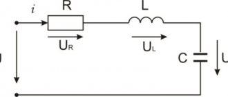
Low-power power supplies (up to several hundred watts) usually use single-phase rectifiers.
In powerful sources it is advisable to use three-phase rectifiers. Rectifiers have the following main parameters: a) average value of output voltage uout
Uav= 1/T· T∫0uoutdt
where T is the network voltage period (for an industrial network - 20 ms);
- average value of output current ioutx and Iav= 1/T· T∫0ioutdt
- output voltage ripple factor ε = Um/ Uav, where Um is the amplitude of the lowest (fundamental) harmonic of the output voltage. The ripple factor is often measured as a percentage.
Let's denote it by ε %: ε % = Um/Uav · 100%
These parameters are the most important when using a rectifier.
Rectifier parameters
When designing a rectifier, the following parameters are also widely used to characterize its internal features:
- effective value Uin of the rectifier input voltage;
- maximum reverse voltage Urev.max on a separate diode or thyristor (i.e. on the valve). This voltage is usually expressed through voltage Uav;
- average value Id.av of the current of an individual valve;
- maximum (amplitude) value Id.max of the current of an individual valve.
Currents Id.av and Id.max are usually expressed through Iav. The Urev.max value is used to select a valve based on voltage. Values
Id.sri Id.max are used to select a valve based on current. Here it should be borne in mind that due to the low thermal inertia of the semiconductor valve, it can fail even in the case when its average current Id.srm is small, but the maximum current Id.max is large.
Output voltage value
Since a full-wave rectifier produces an output signal during both half-cycles, it has twice as many positive cycles as a half-wave rectifier. As a result, the average voltage value is also twice as large:
The average voltage value per cycle is calculated using the following formula:
This equation tells us that the DC voltage value is about 63.6% of the peak value. For example, if the peak voltage of the input signal is 10 V, the voltage at the output of the rectifier will be 6.36 V
When you measure the signal from the output of a full-wave rectifier using a voltmeter, the reading will be equal to the average value.
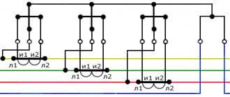
Three-phase rectifier circuit with zero terminal
Its timing diagrams are shown in Fig. 2.76.
The ripple factor of the rectified voltage is 0.25, while for a full-wave single-phase rectifier the ripple factor is 0.67. The ripple frequency in a three-phase rectifier is three times higher than the frequency of the supply network.
Semiconductor single-phase rectifiers for power supplies.
Classification, properties, diagrams, online calculator. Calculation of the capacity of the smoothing capacitor.“Why doesn’t the remote control work? “Of course, I’m not an electrician, but, in my opinion, the remote control doesn’t work because there’s no TV.”
- Why don’t we still need a professional electrician? - For what? Yes, for a lot of reasons! For example, in order to be aware that not a single electronic device can do without a power source, or more precisely without an AC to DC mains voltage converter. - What about the electrician? - Electrician, electrician... What is an electrician?... “Electrician Sidorov fell from a pole and cursed politely...”
So let's get started. A rectifier is an electrical device designed to convert alternating voltage into direct voltage. The rectifier contains a transformer necessary to convert the network voltage Uc to the value U2 determined by the load requirements; a valve group (in our case, a diode group), which ensures one-way current flow in the load circuit; a filter that transmits a constant voltage component to the output of the circuit and smoothes out voltage ripples .
Calculating a transformer is a cumbersome thing and will not be considered within the scope of this article, so let’s move on immediately to the main and most common circuits of rectifiers for power supplies of electronic equipment. In the process of narration, let's make the assumption that by the values of alternating voltages and currents in rectifier circuits we will mean their effective (effective) values: Uact = Uampl/√2 and Irms = Iampl/√2 . These are the values that are given in the passport characteristics of transformer windings, and most measuring instruments display nothing more than exactly the effective values of alternating current signals.
Half wave rectifier.
Fig.1
Figure 1 shows a single-phase, half-wave rectification circuit, as well as voltage oscillograms at various points (black - load voltage in the absence of smoothing capacitor C1, red - with a capacitor). In this type of rectifier, the voltage from the secondary winding of the transformer is supplied to the load through the diode only during positive half-cycles of the alternating voltage. During negative half-cycles, the semiconductor is closed, and voltage is supplied to the load only from the capacitor charged in the previous half-cycle. A half-wave rectifier circuit is used extremely rarely and only to power circuits with low current consumption due to the high level of ripple of the rectified voltage, low efficiency, and inefficient use of the overall power of the transformer.
Here, the transformer winding must provide a current value equal to twice the maximum current in the load Irev = 2×Iload and open-circuit voltage ~U2 ≈ 0.75×Un . When choosing diode D1 for this type of circuit, you should adhere to the following parameters: Uform > 3.14 × Un and Imax > 3.14 × In .
Let's move on. Full-wave rectifier with zero point .
Fig.2
The circuit shown in Fig. 2 is a combination of two antiphase half-wave rectifiers connected to a common load. In one half-cycle of the alternating voltage, current enters the load from the upper half of the secondary winding through the open diode D1, in the other half-cycle - from the bottom, through the second open diode D2. Like any full-wave rectifier circuit, this rectifier circuit has a ripple level that is 2 times lower than that of a half-wave rectifier circuit. The disadvantages include the more complex design of the transformer and the same as in the half-wave circuit - the irrational use of transformer copper and steel.
Each of the transformer windings must provide a current value equal to the value of the maximum current in the load Irev = Iload and open-circuit voltage ~U2 ≈ 0.75×Un . Semiconductor diodes D1 and D2 must have the following parameters: Uform > 3.14×Un and Imax > 1.57×In .
And finally, a classic of the genre - Bridge circuits of full-wave rectifiers .
Fig.3
Figure 3 on the left shows a circuit of a unipolar full-wave bridge rectifier using one transformer winding. The voltage graphs at the input and output of the rectifier are similar to the oscillograms shown in Fig. 2. During the positive half-cycle of the alternating voltage, current flows through the circuit formed by D2 and D3, during the negative half-cycle - through the circuit D1 and D4. In both cases, the direction of the current flowing through the load is the same.
If we compare this circuit with the previous rectifier circuit with a zero point, the bridge has a simpler transformer design with the same ripple level, less stringent requirements for the reverse voltage of the diodes, and most importantly, a more rational use of the transformer and the ability to reduce its overall power. The disadvantages include the need to increase the number of diodes, which leads to increased heat losses due to a greater voltage drop in the rectifier.
The transformer winding must provide a current value equal to Irev = 1.41×Iload and open-circuit voltage ~U2 ≈ 0.75×Un . Semiconductor diodes should be selected based on the following considerations: Uform > 1.57×Un and Imax > 1.57×In .
If the transformer has two identical secondary windings, or one with a lead tapped from the middle, the unipolar circuit is converted into a bipolar rectifier circuit with a middle point (Fig. 3 on the right). Naturally, bipolar diodes should be selected based on the double values of Urev and Imax in relation to a unipolar circuit.
The values of Urev and Imax are given based on the largest (amplitude) value of the reverse voltage applied to one diode, and the largest (amplitude) value of the current through one diode in the absence of smoothing filters at the output.
Capacitor C1 in all circuits is the simplest filter that isolates the DC component of the voltage and smoothes out voltage ripples in the load. For rectifiers that do not contain a stabilizer, its capacity is calculated using the formulas: C1 = 6400×In/(Un×Kp) for half-wave rectifiers and C1 = 3200×In/(Un×Kp) for full-wave rectifiers, where Kp is the ripple coefficient, numerically equal to the ratio of the amplitude value of the pulsating voltage to its constant component. For stabilized power supplies, the capacity of C1 can be reduced by 5-10 times.
“The ripple coefficient is chosen independently depending on the expected load, which allows DC power supply of a very certain “purity”: 10-3 ... 10-2 (0.1-1%) - small-sized transistor radios and tape recorders, 10-4 ... 10-3 (0.01-0.1%) - radio and intermediate frequency amplifiers, 10-5... 10-4 (0.001-0.01%) - preliminary stages of audio frequency amplifiers and microphone amplifiers.” - the printed publication teaches us authoritatively.
Well, at the end of the day, let’s present a simple online table.
RECTIFIER CALCULATOR FOR POWER SUPPLY.
And on the next page we will look at smoothing filters for power rectifiers, not only capacitive, but also inductive, as well as active filters on bipolar transistors.
Series and parallel connections of diodes.
If for the rectifier circuit it is impossible to select the desired type of diode in accordance with the specified value of the reverse voltage or forward current, then two or more diodes of the same type with lower parameter values are used, including these diodes in series or in parallel.
Parallel connection of diodes
Parallel connection of diodes
When parallel connection of diodes
due to possible scattering of parameters, their currents will be different. One of these currents may exceed the maximum permissible value, which will lead to failure of first one and then the other diode. A more uniform distribution of current between parallel-connected diodes is achieved by connecting resistors Rd of the same value in series with each of them. The resistance of the resistors Rd should be 5...10 times greater than the resistance of the diode in the forward direction. In powerful rectifier devices, inductive current equalizers are used for the same purpose.
Calculation of parallel connection of diodes
To start the calculation, you need to determine the required number of parallel-connected diodes
, based on the fact that the current passing through one diode should not exceed the maximum permissible current value for a given type of diode, then the number of parallel-connected diodes will be equal to
, where Im is the maximum current value passing through the diodes, kT is the current load factor ( can take values from 0.5 to 0.8), Inp is the average forward current for a given type of diode.
For fractional values of the estimated number of diodes, rounding is carried out upward.
value of additional resistors
is determined by the formula
, where n is the number of rectifier diodes, Unp.cp is the constant forward voltage for a given type of diode.
The calculated resistance of additional resistors is rounded to the nearest standard resistance.
Example of calculation of parallel connection of diodes
Calculate a rectifier circuit that allows you to obtain a rectified current I rectified = 550 mA if D226B diodes are used.
Since the average forward current of the D226B diode Ipr. av = 300 mA, then it is necessary to use several parallel-connected diodes with additional resistors. Let's calculate the number of parallel-connected diodes, take kT = 0.8
Let's take n = 3.
Let's find the value of the resistance of additional resistors
Let's choose a resistor from the standard range of resistances E24 (± 5%) Rext = 6.2 Ohm
Online calculator for calculating the connection of rectifier diodes
Series connection of diodes
Series connection of diodes
To ensure that the selected type of diode can operate in a rectifier circuit with a reverse voltage exceeding its maximum permissible value, diodes of the same type should be connected in series
. If the parameters do not match, then one of the diodes is under significantly higher voltage than the other. This can lead to breakdown of one and then another diode. Equalization of the reverse voltage on series-connected diodes is achieved by shunting each of the diodes with a resistor Rsh. The current flowing through these resistors should be 5...10 times greater than the maximum possible reverse current of the diodes. In powerful high-voltage rectifier devices, for the same purpose, diodes are shunted with capacitors Сш or an RC circuit.
Calculation of series connection of diodes
To start the calculation, you need to determine the number of diodes connected in series
, based on the fact that the voltage drop on each individual diode should not exceed the amplitude voltage value, then the number of diodes connected in series will be equal to
, where
Um is the amplitude value of the voltage passing through the diode, kH is the voltage load factor (can take values from 0. 5 to 0.8), Uobp max - maximum permissible reverse voltage of the diode.
For fractional values of the estimated number of diodes, rounding is carried out upward.
Shunt resistor resistance values
is determined by the formula
, where
Iobp max is the maximum permissible reverse current of the diode at the maximum temperature.
An example of calculating a series connection of diodes
Calculate the rectifier circuit for a voltage with an amplitude value of 700V using D226B diodes.
Since the maximum permissible reverse voltage of the diode is Urev.max = 300V, for rectification it is necessary to use a chain of series-connected diodes with shunt resistors. Let's calculate the number of series diodes, take kH = 0.7
Let's take n = 4
Let's find the value of the resistance of the shunt resistors
Let's choose a resistor from the standard range of resistances E24 (± 5%) Rsh = 1 MOhm
The inclusion of additional and shunt resistors is inevitably associated with an increase in power losses and a decrease in the efficiency of the rectifier circuit.
Online calculator for calculating the connection of rectifier diodes
Half wave converter
Below is a typical diagram of such a device with a minimum of elements.
Scheme: the simplest converter
Designations:
- Tr – transformer;
- DV valve (diode);
- Cf – capacitance (plays the role of a smoothing filter);
- Rn – connected load.
Now let's look at the oscillogram at control points U1, U2 and Un.
Oscillogram taken at control points U1, U2 and Un
Explanation:
- control point U1 displays a diagram taken at the device input;
- U2 – diagram in front of the capacitive smoothing filter;
- Un – oscillogram at the load.
The timing diagram clearly shows that after the valve (diode), the rectified voltage is represented in the form of characteristic pulses consisting of positive half-cycles. When such a pulse occurs, the charge of the capacitive filter accumulates, which is discharged during the negative half-cycle, this allows the pulsations to be somewhat smoothed out.
The disadvantages of such a scheme are obvious - it is low efficiency, due to the high level of ripple. But despite this, devices of this type find their use in circuits with low current consumption.