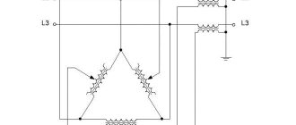
Figure 2a - Cold junction compensation
Accurate performance of CHS is critical to the accuracy of temperature measurements. The accuracy of the CHS depends on two factors: the accuracy of the reference temperature measurement and the proximity of the reference measurement point to the cold junction. Many transmitters use an isothermal terminal block (often made of copper) with a built-in precision thermistor, RTD, or transistor to measure the temperature of the block.
TIP: Use field transmitters rather than hard-wired transmitters directly to the control room.
Manufacturing of thermocouples
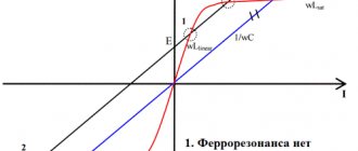
The process begins with selecting a high quality wire of the material required for the type of thermocouple being manufactured. Wires are connected in various ways, including twisting, compression, soldering, incl. and high temperature, as well as various types of welding (for example, narrow seam welding and butt welding). To obtain the best performance, the hot junction must be mechanically strong, electrically continuous, and free from any chemical contaminants from the welding or soldering materials. In the manufacture of high-quality thermocouples, much attention is paid to the choice of wire grade and control of the manufacturing process.
See Figure 3a.
Advice: A junction obtained by twisting wires very quickly loses its properties, and it is not recommended to use this method of obtaining a junction.
Figure 3a - Methods for making a hot junction
3.1 Types of junctions
Thermocouple junctions are manufactured in a variety of configurations, each with its own advantages for specific applications. Junctions can be grounded or ungrounded, and two-element thermocouples can be insulated or non-insulated. See Figure 3.1a.
Figure 3.1a - Hot junction configurations
Grounded thermocouple junctions are formed when the thermocouple junction is connected to the sensor shell. Grounded junctions have better thermal conductivity, which in turn increases performance. However, grounding also makes thermocouple circuits more susceptible to electrical noise, which can corrupt the thermocouple voltage signal if the test instrument does not provide isolation. (All high quality transmitters and I/O boards include electrical isolation as standard.) A grounded junction is also more susceptible to contamination by chemical contaminants over time.
Ungrounded junctions are obtained when the thermocouple elements are not connected to the primary transducer shell, but are surrounded by insulating powder. Ungrounded junctions are slightly slower than grounded junctions, but are less sensitive to electrical noise.
Open junction thermocouples have a hot junction protruding from the sealed end of the shell, providing high performance. Sealing prevents moisture or other contaminants from entering the shell. Typically, such thermocouples are used only in non-corrosive gases, such as air ducts.
3.2 Thermocouples with two sensing elements
Two-sensing thermocouples come in three different types. See Figure 3.1a.
Isolated designs occur when two independent thermocouple junctions are placed in the same enclosure. Insulated junctions may give different temperature readings, but may show drift in readings due to contamination of one of the elements with chemical impurities. If one of the junctions fails, it does not necessarily affect the second junction.
Non-insulated designs occur when two thermocouple junctions are placed in a single sheath and all four thermocouple wires are physically connected. Non-insulated junctions give the same temperature reading to increase the reliability of the measurement at a given point. However, if one of the junctions fails, it most likely means both junctions failed at the same time.
Thermocouple in a gas control system
There are two options for operating the combustion front sensor. The first is used in modern boilers equipped with electronic automation for monitoring and controlling the heating process. As a rule, the contact from the thermocouple is connected to the ignition unit. The voltage from the thermoEMF supplied to the board opens an electronic switch based on a thyristor or transistor. And that, in turn, opens the gas supply solenoid valve.
When the boiler is turned on, for 20-25 seconds, until the junction has warmed up, the electronic key is held open by a capacitor. If no voltage is supplied to the key from the thermocouple, the capacitor discharges, the valve closes, and the gas supply stops.
The second option is used in old floor-standing gas boilers without electronic components. Switching on is performed by pressing a button and mechanically unlocking the magnetic valve. If the gas burner is ignited and a thermoEMF appears on the thermocouple, then the generated voltage blocks the valve in the open position.
Types of thermocouples
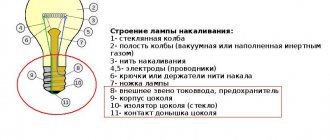
There are many types of thermocouples, using different combinations of metals. These combinations have different output characteristics that determine the temperature range over which a particular thermocouple can be used and the corresponding voltage output. See Figure 4a and Table 4b. The higher the output voltage amplitude, the higher the measurement resolution, which increases the repeatability and accuracy of the results. There are relationships between measurement resolution and temperature range that make certain types of thermocouples suitable for certain ranges and applications.
Figure 4a - Dependencies of emf.
Thermocouple vs. Temperature for Commonly Used Thermocouple Types Table 4b - Detailed Thermocouple Table
| NSH | Thermoelectrode | Combination of metals | Maximum application temperature | Possible temperature range | |
| °C | °F | ||||
| B | R N | platinumrhodium platinumrhodium | 1825 | 3320 | from 0 to 1820°C from 32 to 3308°F |
| E | R N | chromel constantan | 1220 | 2230 | from -270 to 1,000°C from -454 to 1832T |
| J | R N | Iron Constantan | 1220 | 2230 | from -200 to 1200°C from -328 to 2192T |
| TO | R N | Chromel alumel | 1400 | 2550 | from -270 to 1372°C from -454 to 2501T |
| N | R N | Nichrosil nisil | 1340 | 2440 | from -270 to 1300°C from -454 to 2372T |
| R | R N | platinumrhodium platinum | 1770 | 3215 | -50 to 1768°C -58 to 3214°F |
| S | R N | platinumrhodium platinum | 1770 | 3215 | -50 to 1768°C -58 to 3214°F |
| T | R N | copper constantan | 1080 | 1980 | -270 to 400°C -454 to 752°F |
WHAT ARE THE RANGES OF MEASURED TEMPERATURES FOR THERMOCOUPLES?
There are many types of thermocouples, using different combinations of metals. These combinations have different output characteristics that determine the temperature range over which a particular thermocouple can be used and the corresponding voltage output. The greater the output voltage amplitude, the higher the measurement resolution, which increases the repeatability and accuracy of the results. There are relationships between measurement resolution and temperature range that make certain types of thermocouples suitable for certain ranges and applications.
There are types of thermocouples that are capable of measuring very low temperatures, down to -270°C (-464°F), and other types that are capable of measuring temperatures up to 1768°C (3214°F).
4.1 Thermocouple type K, chromel - alumel
• Chromel® is an alloy containing 90% nickel and 10% chromium, while Alumel® is an alloy containing 95% nickel, 2% manganese, 2% aluminum and 1% silicon.
• Type K thermocouples are one of the most common general purpose thermocouples, with a sensitivity of approximately 41 mV/°C.
• The Chromel® thermode has a positive potential relative to the Alumel® thermode.
• They are inexpensive thermocouples, have a temperature range of -270°C to +1372°C (-454°F to +2501°F) and are relatively linear.
• The nickel content makes the alloy magnetic and, as with other magnetic metals, the thermocouple output is deflected when the material reaches its Curie temperature, which is approximately 350°C (662°F) for Type K thermocouples. The Curie temperature is the temperature in which a magnetic material undergoes a major change in its magnetic properties, causing a significant shift in the output signal.
• These thermocouples can be used in permanently oxidizing or neutral environments.
• They are primarily used at temperatures above 538°C (1000°F)
• Exposure to sulfur causes premature failure of thermocouples.
• Operation at certain low oxygen concentrations causes deviation
in the work, which is called the preferential oxidation of chromium in the positive thermoelectrode, which leads to a condition commonly called “green rot” and which causes a large negative calibration drift, most severe in the range of 816 - 1038 °C (1500 - 1900 °F). This condition can be prevented/reduced by ventilation or inert sealing of the protective tube.
• It is not recommended to expose the thermocouple to temperatures that cycle above and below 1000 °C (1800 °F) because the output signal then changes due to hysteresis effects.
TIP: Historically, it has been suggested that Type K thermocouples should always be used unless there is a reason to use other types of thermocouples.
4.2 Type J thermocouple, iron-constantan
• The temperature range of J-type thermocouples is narrower than that of K-type thermocouples, from -200 to +1200 °C (346 to 2193 °F), but they have higher sensitivity, which is about 50 µV/ °C.
• They exhibit a very linear response from 149 to 427 °C (300 to 800 °F) and become brittle below 0 °C (32 °F)
• At the Curie temperature of iron, which is 770 °C (1418 °F), a sharp and continuous measurement of the output characteristic occurs, which determines the practically achievable upper temperature limit.
• Iron is susceptible to oxidation at temperatures above 538°C (1000°F), which negatively affects
on the accuracy of thermocouples. In such conditions, only large diameter wire should be used.
• Type J thermocouples are suitable for use in vacuum, reducing or inert environments.
• When used in an oxidizing environment, thermocouple life will be reduced.
• Bare components should not be exposed to sulfur containing environments at temperatures above 538°C (1000°F)
4.3 Thermocouple type E, chromel - constantan)
• Chromel is an alloy consisting of 90% nickel and 10% chromium, and is used to make the positive thermoelectrode
• Constantan is an alloy usually consisting of 55% copper and 45% nickel
• Type E thermocouples have a temperature range of -270 to 1000°C (-454°F to 1832°F)
• These are non-magnetic thermocouples and have the highest output voltage variation with temperature of any standard thermocouple type (68 µV/°C)
• They also have a greater tendency to drift than other types.
• These thermocouples are recommended for use in permanently oxidizing or inert environments.
• The limits of their errors when used at temperatures below zero have not been established.
4.4 Type T thermocouples, copper - constantan
• Type T thermocouples have a sensitivity of 38 µV/
°C and temperature range from -270°C to 400°C (-454°F to 752°F)
• They can be used in oxidizing, reducing or inert environments, as well as in vacuum
• They are highly resistant to corrosion in humid environments.
• These thermocouples exhibit good linearity and are typically used at very low (cryogenic) to moderate temperatures.
4.5 Thermocouple type N, nichrosil - nisil
• Nichrosil is a nickel alloy containing 14.4% chromium, 1.4% silicon and 0.1% magnesium, and is the positive leg in a thermocouple
• Nisil is an alloy of nickel and 4.4% silicon
• Type N thermocouple is the latest design approved by international standards and its application is increasing worldwide.
• These alloys allow N-type thermocouples to achieve significantly higher thermoelectric stability than E, J, K, and T base metal thermocouples.
• Type N thermocouples have a sensitivity of 39 µV/
°C and possible temperature range from -270°C to 1300T (-454 °F to 2372 °F)
• Type N thermocouples have been used reliably for extended periods of time at temperatures up to at least 1200 °C (2192 °F)
• Some studies have shown that in oxidizing environments, the thermoelectric stability of N-type thermocouples is approximately the same as that of R- and S-type noble metal thermocouples at temperatures up to approximately 1200 °C (2192 °F)
• Type N thermocouples should not be used in vacuum or reducing environments, or in environments that change from reducing to oxidizing.
4.6 Thermocouple types R and S, platinum-rhodium-platinum
• Type R (platinum-13% rhodium/platinum) and type S (platinum-10% rhodium/platinum) thermocouples have a possible temperature range of -50 to 1768°C (58°F to 3214°F)
• Both types have a sensitivity of about 10 µV/°C and are therefore not suitable for low temperature applications where other types would be better.
• Because they are made from a platinum alloy, they are quite expensive and are usually used at very high temperatures where other thermocouples do not perform well.
• Due to their high stability, Type S thermocouples are used to determine the International Temperature Scale between the freezing point of antimony (630.5°C / 1166.9°F) and the melting point of gold (1064.43°C (1945.4°F))
• Proper installation requires that the thermocouple be protected by a non-metallic protective tube and ceramic insulators.
• Prolonged exposure to high temperatures causes metal grain growth and can lead to
to mechanical failure and negative reading loss due to diffusion of rhodium into the pure platinum thermoelectrode, as well as volatilization of rhodium.
• In general, R type thermocouples are used in industry and S type thermocouples are mainly used in laboratories.
4.7 Type B thermocouples, platinum-rhodium - platinum-rhodium
• Type B thermocouples (platinum-30% rhodium/platinum-6% rhodium) have a possible temperature range of approximately 0 °C to 1820 °C (32 °F to 3308 °F).
• Type B thermocouples are typically placed in clean air/oxidizing environments but should not be exposed to reducing environments.
• The increased rhodium content of Type B thermocouples helps reduce grain growth, allowing a slightly larger temperature range than Type R and S thermocouples.
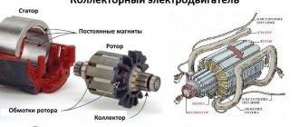
A thermocouple (thermoelectric converter) is a device used in industry, scientific research, medicine, and in automation systems for measuring temperature. A thermocouple (thermoelectric converter) is two conductors made of different materials, soldered on one side (hot junction) and free on the other side (cold junction). The device is simple, and the principle of operation is the same - when a thermocouple is heated or cooled, different metals change temperature at different rates, and the difference allows thermoelectromotive force (EMF) to arise, or, in other words, the Seebeck effect occurs. Thanks to this, it is possible to measure the temperature.
Direct participation in the measurement falls on the hot junction, and the free ends are connected to the measuring device. The main characteristic of thermocouples is their Type, which is determined by the type of welded metals.
The device receives a voltage in millivolts from the thermocouple, which it compares with a voltage table (according to the type of thermocouple), the table is stored in the device’s memory and reflects the current measurement value.
Table for Type K (NiCr-Ni)
| Type K Temp. oC | 0 | -10 | -20 | -30 | -40 | -50 | -60 | -70 | -80 | -90 |
| -200.00 | -5,891 | -6,035 | -6,158 | -6,262 | -6,344 | -6,404 | -6,441 | -6,458 | ||
| -100.00 | -3,553 | -3,852 | -4,138 | -4,410 | -4,669 | -4,912 | -5,141 | -5,354 | -5,550 | -5,730 |
| 0 | -0,392 | -0,777 | -1,156 | -1,527 | -1,889 | -2,243 | -2,586 | -2,920 | -3,242 | |
| 0 | 10 | 20 | 30 | 40 | 50 | 60 | 70 | 80 | 90 | |
| 0 | 0,397 | 0,796 | 1,203 | 1,611 | 2,022 | 2,436 | 2,850 | 3,266 | 3,681 | |
| 100 | 4,095 | 5,549 | 4,919 | 5,327 | 5,733 | 6,137 | 6,539 | 6,939 | 7,338 | 7,737 |
| 200 | 8,137 | 8,537 | 8,938 | 9,341 | 9,745 | 10,151 | 10,560 | 10,969 | 11,381 | 11,793 |
| 300 | 12,207 | 12,623 | 13,039 | 13,456 | 13,874 | 14,292 | 14,712 | 15,132 | 15,552 | 15,974 |
| 400 | 16,395 | 16,818 | 17,241 | 17,664 | 18,088 | 18,513 | 18,938 | 19,363 | 19,788 | 20,214 |
| 500 | 20,640 | 21,066 | 21,493 | 21,911 | 22,346 | 22,772 | 23,198 | 23,624 | 24,050 | 24,476 |
| 600 | 24,902 | 25,327 | 25,751 | 26,176 | 26,599 | 27,022 | 27,445 | 27,867 | 28,288 | 28,709 |
| 700 | 29,128 | 29,547 | 29,965 | 30,383 | 30,799 | 31,214 | 31,629 | 32,042 | 32,455 | 32,866 |
| 800 | 33,277 | 33,686 | 34,095 | 34,502 | 34,909 | 35,314 | 35,718 | 36,121 | 36,524 | 36,925 |
| 900 | 37,325 | 37,724 | 38,122 | 38,519 | 38,915 | 39,310 | 39,703 | 40,096 | 40,488 | 40,879 |
| 1000 | 41,269 | 41,657 | 42,045 | 42,432 | 42,817 | 43,202 | 43,585 | 43,968 | 44,349 | 44,729 |
| 1100 | 45,108 | 45,486 | 45,863 | 46,238 | 46,612 | 46,985 | 47,356 | 47,726 | 48,095 | 48,462 |
| 1200 | 48,828 | 49,192 | 49,555 | 49,916 | 50,276 | 50,633 | 50,990 | 51,344 | 51,697 | 52,049 |
| 1300 | 52,398 | 52,747 | 53,093 | 53,439 | 53,782 | 54,125 | 54,466 | 54,807 |
Table for Type J (Fe-CuNi)
| Type J Temp. oC | 0 | -10 | -20 | -30 | -40 | -50 | -60 | -70 | -80 | -90 |
| -200,00 | -7,890 | -8,096 | ||||||||
| -100,00 | -4,632 | -5,016 | -5,426 | -5,801 | -6,159 | -6,499 | -6,821 | -7,122 | -7,402 | -7,659 |
| 0 | 0,000 | -0,501 | -0,995 | -1,481 | -1,960 | -2,431 | -2,892 | -3,344 | -3,785 | -4,215 |
| 0 | 10 | 20 | 30 | 40 | 50 | 60 | 70 | 80 | 90 | |
| 0 | 0 | 0,507 | 1,190 | 1,536 | 2,058 | 2,585 | 3,115 | 3,649 | 4,186 | 4,725 |
| 100 | 5,269 | 5,812 | 6,590 | 6,907 | 7,457 | 8,008 | 8,560 | 9,113 | 9,667 | 10,222 |
| 200 | 10,777 | 11,332 | 11,887 | 12,442 | 12,998 | 13,553 | 14,108 | 14,663 | 15,217 | 15,771 |
| 300 | 16,325 | 16,879 | 17,432 | 17,984 | 18,537 | 19,089 | 19,640 | 20,192 | 20,743 | 21,295 |
| 400 | 21,846 | 22,397 | 22,949 | 23,501 | 24,054 | 24,607 | 25,161 | 25,716 | 26,272 | 26,829 |
| 500 | 27,388 | 27,949 | 28,511 | 29,075 | 29,642 | 30,210 | 30,782 | 31,356 | 31,933 | 32,513 |
| 600 | 33,096 | 33,683 | 34,273 | 34,867 | 35,464 | 36,066 | 36,671 | 37,280 | 37,893 | 38,510 |
| 700 | 39,130 | 39,754 | 40,382 | 41,013 | 41,647 | 42,283 | 42,922 | 43,563 | 44,207 | 44,852 |
| 800 | 45,498 | 46,144 | 46,790 | 47,434 | 48,076 | 48,716 | 49,354 | 49,989 | 50,621 | 51,249 |
| 900 | 51,875 | 52,496 | 53,115 | 53,729 | 54,341 | 54,948 | 55,553 | 50,155 | 56,753 | 57,349 |
| 1000 | 57,942 | 58,533 | 59,121 | 59,708 | 60,293 | 60,876 | 61,459 | 62,039 | 62,619 | 63,199 |
| 1100 | 63,777 | 64,355 | 64,933 | 65,510 | 66,087 | 66,664 | 67,240 | 67,815 | 68,390 | 68,964 |
| 1200 | 69,536 |
Table for Type L (Fe-CuNi)
| Type L Temp. oC | 0 | -10 | -20 | -30 | -40 | -50 | -60 | -70 | -80 | -90 |
| -200,00 | -8,15 | |||||||||
| -100,00 | -4,75 | -5,15 | -5,53 | -5,9 | -6,26 | -6,6 | -6,93 | -7,25 | -7,56 | -7,86 |
| 0 | 0 | -0,51 | -1,02 | -1,53 | -2,03 | -2,51 | -2,98 | -3,44 | -3,89 | -4,33 |
| 0 | 10 | 20 | 30 | 40 | 50 | 60 | 70 | 80 | 90 | |
| 0 | 0 | -0,52 | -1,05 | -1,58 | -2,11 | -2,65 | -3,19 | -3,73 | -4,27 | -4,82 |
| 100 | 5,37 | 5,92 | 6,47 | 7,03 | 7,59 | 8,15 | 8,71 | 9,27 | 9,83 | 10,39 |
| 200 | 10,95 | 11,51 | 12,07 | 12,63 | 13,19 | 13,75 | 14,31 | 14,88 | 15,44 | 16 |
| 300 | 16,56 | 17,12 | 17,68 | 18,24 | 18,8 | 19,36 | 19,92 | 20,48 | 21,04 | 21,6 |
| 400 | 22,16 | 22,72 | 23,29 | 23,86 | 24,43 | 25 | 25,57 | 26,14 | 26,71 | 27,28 |
| 500 | 27,85 | 28,43 | 29,01 | 29,59 | 30,17 | 30,75 | 31,33 | 31,91 | 32,49 | 33,08 |
| 600 | 33,67 | 34,26 | 34,85 | 35,44 | 36,04 | 36,64 | 37,25 | 37,85 | 38,47 | 39,09 |
| 700 | 39,72 | 40,35 | 40,98 | 41,62 | 42,27 | 42,92 | 43,57 | 44,23 | 44,89 | 45,55 |
| 800 | 46,22 | 46,89 | 47,57 | 48,25 | 48,94 | 49,63 | 50,32 | 51,02 | 51,72 | 52,43 |
From time to time, many customers have problems determining the type of thermocouple when there are no descriptive characteristics and it is necessary to select a replacement or an analogue. Solving it is quite simple; the main thing is to know the principles of thermocouple classification. The thermocouple classification system includes color coding for conductor insulation.
For example, the European alloy classification for thermocouples Type L (Fe-CuNi) and Type J (Fe-CuNi) is the same, it is very important to understand that they are not interchangeable and the output voltage at the same temperature for these thermocouples will be different. A chart of standards for wire insulation color coding will be very helpful in determining the type of thermocouple if there is no marking.
It is also necessary to note the type of design of the sensor part (hot junction) of thermocouples. They come with insulated and non-insulated working junctions.
The performance indicator for measuring temperature is higher for a non-insulated thermocouple than for an insulated one. But this makes the connection diagram more complicated and requires isolated input modules. Since the difference in performance is not so significant, thermocouples with an insulated junction are mainly used.
Like all temperature meters, thermocouples are classified according to accuracy.
For example, accuracy classes Type K and Type J, the most common thermocouples in use
Class 1 : ±1.5 °C or ±0.004 x T (Type K: -40 to +1000 °C), (Type J: -40 to +750 °C)
Class 2 : ±2.5 °C or ±0.0075 x T (Type K: -40 to +1200 °C), (Type J: -40 to +750 °C)
Technical characteristics of the most popular thermoelectric converters (thermocouples) in accordance with GOST 3044 are given in the table:
| Thermocouple type | NSH thermocouples | Positive thermoelectrode material | Negative thermoelectrode material | Range of measured temperatures, °C | Operating temperature range, °C |
| THC Type L | XK( L ) | Chromel alloy NX9.5 (90.5% Ni + 9.5% Cr) | Copel alloy MNMts 43-0.5 (56% Cu + 44% Ni) | -200…800 | -200…600 |
| TXA Type K | HA (K) | Chromel alloy NX9.5 (90.5% Ni + 9.5% Cr) | Alumel alloy NMTs AK 2-2-1 (94.5% Ni + 5.5% Al, Si, Mn, Co) | -200…1300 | -200…1000 |
| TZHK Type J | LCD (J) | Iron (Fe) | Constantan alloy (55% Cu + 45% Ni, Mn, Fe) | -200…900 | -200…700 |
| Chamber of Commerce and Industry Type S | PP (S) | Platinum-rhodium alloy PR-10 (90% Pt + 10% Rh) | Platinum (Pt) | 0…1600 | 0…1300 |
| TPR Type B | OL (B) | Platinum-rhodium alloy PR-30 (70% Pt + 30% Rh) | Platinum-rhodium alloy PR-6 (94% Pt + 4% Rh) | 300…1800 | 300…1600 |
Many customers are mistaken in the fact that if a thermocouple type has an operating range, for example, 1200°C, then all thermocouple models with this type will work in this range. An unprotected thermocouple junction will quickly burn out and the thermocouple will fail. That is why, depending on the measurement tasks and operating ranges, there are thermocouple models that differ in design and degree of protection. The most common junction/thermocouple protection is a metal sheath or sleeve made of Inconel 600 (2.4816, a nickel-based superalloy). The insulation for the junction is magnesium oxide (MgO), compressed under pressure. This protection makes the thermocouple resistant to the most extreme operating conditions (high pressure, vibration, shock), allows it to withstand high mechanical loads and ensures a long service life of the thermocouple, and, depending on the diameter, allows the thermocouple to be flexible.
A striking example of such a thermocouple, which is quite universal in its applied nature, is the thermocouple in a heat-resistant sheath MKG/E:
| Thermocouple Type K (NiCr-Ni), glass fiber cable Model: MKG/E | ||
| The MKG/E thermocouple is enclosed in a heat-resistant sheath made of pressurized magnesium oxide. This makes it resistant to the most extreme operating conditions. read more… | |
Thermocouple Conductor Color Standards
Thermocouple conductors consist of two separate thermoelectrodes (positive and negative) with colored insulation. Due to the Seebeck effect, thermocouple wires have a specific polarity, so the positive and negative wires must be connected to the correct terminals. There are a variety of conductor insulation color standards available to identify each type.
thermocouples See Table 5a Different standards use unique wire colors to distinguish positive and negative terminals. In North America, the negative terminal is typically red insulated to ASTM E230. But the most widely used thermocouple wire standard in the world is IEC 60584, which states that the negative wire is typically white. It is clear that the standards to which the thermocouple is manufactured must be known in order to correctly connect the wires according to their colors. There are other standards used in various countries, including BS1843 (UK and Czech Republic), DIN43710 (Germany), JIS-C1610 (Japan) and NFC 42-324 (France). See Table 5a.
TIP: The user should check which standard is used in their facility and ensure that the color coding is communicated to installation, commissioning and maintenance personnel.
How does a flame sensor work in a gas boiler?
In appearance, a thermocouple resembles an ordinary copper tube with a fixing nut at the end. Despite its apparent simplicity, the gas boiler thermocouple device is optimized to obtain maximum sensitivity and reliability of the sensor.
The thermocouple consists of four parts:
- tip, head or hot junction of the temperature sensor;
- copper tube - extension cord;
- protective sleeve;
- contact protected by a dielectric washer.
The tip is a joint made of two dissimilar metals or alloys. Two small parts, one of which looks like a rounded cone, the second is the same cone, but smaller.
The inner cone of the tip is made of one alloy, it can be “copel”, inserted into the outer shell of “chromel”. Both parts are soldered under pressure so that a common surface is formed between them. The larger its area, the higher the sensitivity of the thermocouple and the lower the operating temperature.
The sleeve is made of bronze or brass, its task is to protect the seam between the thermocouple head and the copper extension. Inside the copper tube there is a copper conductor, which extends out and ends at a contact pad with an insulating dielectric washer. This end is inserted into the contact connector (+) on the AOGV and is rigidly fixed with a fitting nut. The hot junction is installed on a bracket next to the ignition device.
For gas boilers, an AOGV with a thermocouple, fixed by a fitting or an electrical block, is used. If you have the opportunity to choose, it is better to choose a model with a fitting nut.
The problem is that the voltage on the thermocouple is extremely low; for a chrome-copel junction it does not exceed 25 mV. This means that even slight oxidation of the contact surface can cause unstable operation of the gas boiler ignition system. In those models where the contact pad is fixed with a fitting nut, such problems do not arise.
Thermocouple accuracy
The accuracy of thermocouples is affected by several factors, including the type of thermocouple, its temperature range, purity
material, electrical noise (EMI and RFI), corrosion, junction deterioration and manufacturing process.
Thermocouples are available with a standard tolerance class or a special tolerance class, which are called class 2 and class 1, respectively. The most commonly used international standard is IEC-60584-2. In the United States, the most commonly used standard is ASTM E230. Each standard specifies the tolerance limits that products must meet. See Table 8a and Table 8b. Table 8a - Thermocouple tolerance requirements for compliance with IEC 60584-2
| Types | Accuracy class 1 | Accuracy class 2 | Accuracy class 3 1) | |
| Type T | Temperature Range | -40 °С to +125 °С | -40 °С to +133 °С | -67 °С to +40 °С |
| Accuracy | ±0.5° C | ±1 °С | ±1 °С | |
| Temperature Range | 125 °C to 350 °C | 133 °C to 350 °C | -200 °C to -67 °C | |
| Accuracy | ±0.004 • | t | | ±0.0075 • | t | | ±0.015- | t | | |
| Type E | Temperature Range | -40 °С to +375 °С | -40 °С to +333 °С | -167 °С to +40 °С |
| Accuracy | ±1.5 °С | ±2.5 °С | ±2.5 °С | |
| Temperature Range | 375 °C to 800 °C | 333 °C to 900 °C | -200 °C to -167 °C | |
| Accuracy | ±0.004 • | t | | ±0.0075 • | t | | ±0.015- | t | | |
| Type J | Temperature Range | -40 °С to +375 °С | -40 °С to +333 °С | — |
| Tolerance value | ±1.5 °С | ±2.5 °С | — | |
| Temperature Range | 375 °C to 750 °C | 333 °C to 750 °C | — | |
| Tolerance value | ±0.004 • | t | | ±0.0075 • | t | | — | |
| Type K, Type N | Temperature Range | 0°C to 1100°C | -40 °С to +333 °С | -167 °С to +40 °С |
| Accuracy | ±1 °С | ±2.5 °С | ±2.5 °С | |
| Temperature Range | 1100°С to 1600°С | 333 °C to 1200 °C | -200 °C to -167 °C | |
| Accuracy | ±[1 +0.003 (t-1100)] °С | ±0.0075 • | t | | ±0.015- | t | | |
| Type R, type S | Temperature Range | 0°C TO 1100°C | 0 °C to +600 °C | — |
| Accuracy | ±1 °С | ±1.5 °С | — | |
| Temperature Range | 1100°С to 1600°С | 600 °C to 1600 °C | — | |
| Accuracy | ±[1 +0.003 (t-1100)] °С | ±0.0025 • | t | | — | |
| Type B | Temperature Range | — | — | 600 °C to 800 °C |
| Accuracy | — | — | +4 °С | |
| Temperature Range | — | 600 °C to 1700 °C | 800 °C to 1700 °C | |
| Accuracy | — | ±0.0025 • | t | | ±0.005- | t | | |
1) Thermocouple materials are typically supplied to meet the manufacturing tolerances listed in the table for temperatures above -40°C. However, these materials may not meet the low temperature manufacturing tolerances listed in the Class 3 column for T, E, K, and N thermocouple types. If thermocouples are required to meet Class 3 limits as well as Class 1 or 2, the customer should specify this as this usually requires selection of materials
Tolerances on emf values depending on temperature for thermocouples
NOTE 1—The tolerances in this table apply to new, substantially uniform thermocouple wires typically having a diameter in the range 0.25 to 3 mm and used at temperatures not exceeding the recommended limits of Table 6. If products are used at higher temperatures, these tolerances may not apply.
NOTE 2—For a given temperature, specified in degrees °C, the accuracy specified in °F is 1.8 times greater than the accuracy specified in °C. Where accuracy is specified as a percentage, the percentage value applies to the measured temperature expressed in degrees Celsius. To determine Fahrenheit accuracy, multiply Celsius accuracy by 9/5.
NOTE 3—Caution: Users should be aware of certain characteristics of thermocouple materials, including that the e.m.f.
temperature may change over time; therefore, test results and performance characteristics obtained at the time of manufacture may not necessarily remain constant over the entire period of operation. The accuracies shown in this table apply only to new wires supplied to the user and do not take into account changes in performance during use. The magnitude of this change will depend on factors such as thermoelectrode size, temperature, exposure time, and environment. Additionally, it should be noted that due to possible variations in uniformity, attempting to recalibrate used thermocouples is likely to produce incorrect results and is not recommended. However, it may be advisable to compare a used thermocouple on site with a new or proven thermocouple to ensure its suitability for continued service under the conditions under which the comparison was made. Table 8a— Thermocouple Tolerance Requirements to Comply with ASTM E230-11
| Temperature Range | Accuracy - reference junction at 0°C [32°F] | |||||
| Thermocouple type | °C | °F | Tolerance | Special permissions | ||
| °C (whichever is greater) | °F | °C (whichever is greater) | °F | |||
| T J *E K or N R or S IN | from 0 to 370 | from 32 to 700 | ±1.0 or ±0.75% | Note 2 | ±0.5 or ±0.4% | Note 2 |
| from 0 to 760 | from 32 to 1400 | ±2.2 or ±0.75% | ±1.1 or ±0.4% | |||
| from 0 to 870 | from 32 to 1600 | ±1.7 or ±0.5% | ±0.01 °C or ±0.4% | |||
| 0 to 1260 | from 32 to 2300 | ±2.2 °C or ±0.75% | ±1.1 Tiles ±0.4% | |||
| from 0 to 1480 | from 32 to 2700 | ±1.5 °C or ±0.25% | ±0.6 °C or ±0.1% | |||
| from 870 to 1700 | from 1600 to 3100 | ±0,5% | ±0,25% | |||
| WITH | From 0 to 2315 | from 32 to 4200 | ±4.4 or 1% | Note 2 | Applicable note | |
| TA *EA KA | -200 to 0 | from -328 to 32 | ±1.0 or ±1.5% | IN | ||
| -200 to 0 | from -328 to 32 | ±1.7 or ±1% | IN | |||
| -200 to 0 | from -328 to 32 | ±2.2 or ±2% | IN | |||
*Standard tolerances shown do not apply to Type E Mineral Insulated Metal Sheathed (MIMS) thermocouples. Standard tolerances for MIMS Type E thermocouples are the greater of ±2.2 °C or ±0.75% from 0 to 870 °C and the greater of ±2.2 °C or ±2% from -200 up to 0 °C.
A Thermocouple and thermocouple materials are usually supplied to meet the tolerances given in the table for temperatures above 0 °C. However, these same materials may not meet the tolerances at temperatures below 0 °C in the second part of the table. If materials are required to meet tolerances specified for temperatures below 0°C, the purchaser must indicate this when placing an order. Usually in this case a selection of materials is required.
B Special tolerances for temperatures below 0 °C are difficult to confirm due to limited information available.
However, when discussing delivery between buyer and supplier, it is recommended that the following values for type E and T thermocouples be used as a guide:
Type E, -200 to 0 °C, ±1.0 °C or ±0.5% (whichever is greater)
Type T, -200 to 0 °C, ±0.5 °C or ±0.8% (whichever is greater)
Initial tolerances for Type J thermocouples below 0°C and special tolerances for Type K thermocouples below 0°C are not given due to material characteristics. There are currently no data available for Type N thermocouples at temperatures below 0 °C.
Connection nuances and verification
The verification procedure must be performed if the boiler starts up unstable, or if the electronic ignition unit unexpectedly switches to a continuous start-stop cycle. In the latter case, claims are often made unreasonably about the contacts on the thermocouple. In reality, the compensating capacitor of the ignition unit is to blame.
Be sure to check the new thermocouple. To do this, just connect the multimeter probes to the central contact (+) and the copper tube (-). Set the measurement limit to 1 V or 0.1 V, heat the junction with a candle or gas lighter. There should be at least 18 mV on the screen.
The old thermocouple on a boiler with AOGV can be checked without dismantling the device:
- unscrew the fitting nut of the AOGV block;
- light a papillon;
- connect the probes and take readings.
This method allows you to take the most accurate data. The multimeter should show at least 25-28 mV.
Pay attention to the position of the sleeve with the junction head. It should stand vertically, and the igniter flame should flow around only the upper 3 mm of the temperature sensor. Any other options lead to overheating or underheating of the device.
Measurement speed
The dynamic response of the sensor can be important if the process temperature changes rapidly and the control system needs to provide rapidly changing input signals. A primary sensor installed directly into the process line will be faster than a primary sensor with a thermowell.
It is important to note that if no thermowell is used, the sensing element is exposed to the process environment and cannot be replaced without interrupting the flow, which often requires shutting down the process and draining the process system. Design guidelines in most plants do not allow the use of sensors without thermowells. Such installations are much less safe from the point of view of possible depressurization of process units, they are subject to more frequent failures of primary converters due to exposure to adverse process conditions, and they often require costly process shutdowns to replace a failed primary converter. The use of protective sleeves solves this problem.
But if a thermowell is used, it is obvious that the reaction time increases (response speed decreases) due to the increase in the thermal mass of the assembly. The key to optimizing performance is to reduce mass while maintaining sufficient physical strength to withstand process pressures and fluid flow forces. Smaller diameter thermowells provide faster performance because less material needs to be heated and cooled. It is also important to install the primary converter correctly to achieve high performance. The sensor must be long enough so that its end touches the bottom of the thermowell to ensure good thermal conductivity. The diameter of the primary sensor must also be such that it fits tightly into the protective sleeve and the air gap between the primary sensor and the protective sleeve is minimal. In addition, performance is improved by using a spring-loaded sensor and filling the voids in the sleeve with thermally conductive filler. The characteristics of the medium being measured also affect the performance, especially its flow rate and density. Fast-moving media transmit heat and changing temperature better than slow-moving media, and denser media (liquids) are better conductors of heat than low-density media (gases).
A comparison of the performance of temperature measurement systems using a thermocouple without thermowell or a thermowell-less RTD in a flowing water system showed that the grounded end of the thermocouple has a response speed approximately 2 times faster than a spring-loaded RTD sensor. When measuring in air flow, the TC operates somewhat faster than a thermocouple.
However, these advantages are greatly reduced, if not eliminated, when the sensor is installed in a thermowell. The mass of the thermowell is so large compared to the mass of the primary converter that it clearly has a dominant effect on system performance.
When using a 6 mm (1/4 inch) diameter sensor in a water temperature measurement system, the performance of the thermocouple and RTD is approximately the same, and when using a 3 mm diameter sensor, the thermocouple is slightly faster than the RTD. When measuring air temperature, the performance of thermocouples and RTDs is approximately the same when using both 3 mm (1/8 inch) and 6 mm sensors.
Since very few processes use sensors without thermowells for measurement, the inherent speed advantage of thermocouples is greatly negated. A thoughtful designer selects the best sensor for a given system based on many other factors, and does not rely on the misleading statements that are so often heard: “thermocouples are always faster than RTDs.”