A significant number of drive systems are used to naturally slow down engines when stopped. The time it takes to stop the rotor is measured solely by the inertial moment and the moment of resistance to rotation. Meanwhile, the operation of systems often requires reducing the stopping time of the motor shaft, and in this case, electrical braking of the electric motor seems to be a simple and effective solution. Compared to devices that use mechanical or hydraulic methods, electrical braking of motors has clear advantages in terms of stability of operation and cost-effectiveness of use.
Options for constructing electric brakes
Let's consider several options for braking motors electrically, which can be applied in practice. At the same time, we note the possibility of using braking mechanisms in relation to electric motors of different types. The list of braking techniques considered includes the following:
- countercurrent,
- DC input,
- electronically,
- supersynchronous speed,
- in other ways.
Dynamic braking.
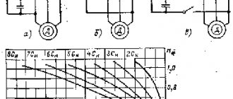
The need for such braking arises in the case when, after disconnecting the engine from the network, its armature continues to rotate under the influence of the kinetic energy of the moving masses of the electric drive. If at the same time the armature winding, disconnected from the network, is shorted to a resistor rt, then the engine will switch to generator mode (the excitation winding must remain connected to the network). The electricity generated in this case is not returned to the network, as happens with regenerative braking, but is converted into heat, which is released in the resistance
In the dynamic braking mode, the armature EMF does not change its direction, but since the armature is disconnected from the network (U = 0), the armature current will change direction, since an EMF Ea will be created
those. will become negative. As a result, the electromagnetic torque will also change direction and become braking (Fig. 13.15, b). The braking process continues until the armature stops completely (n = 0).
Countercurrent braking principle
The motor is disconnected from the power supply, and while the rotor continues to rotate, it is reconnected in antiphase. Such a system creates an effective locking torque, usually higher than the starting torque.
Meanwhile, this effective braking torque must be quickly neutralized so that the engine does not rotate in the opposite direction after stopping. Several control and automation devices are used to ensure that the rotation of the electric motor shaft is slowed down until it stops completely:
- clutch stop sensors,
- centrifugal stop sensors,
- chronometric instruments,
- frequency relay,
- rotor voltage relay (for wound-rotor motors), etc.
Braking a squirrel-cage motor
Before choosing a countercurrent system for an asynchronous motor with a short-circuit rotor, it is important to ensure the resistance of the motor to the countercurrent method, taking into account the required load.
In addition to mechanical stress, this process exposes the rotor to high thermal loads as the energy generated by each operation is dissipated in the rotor body.
The thermal stress in the counterflow is three times greater than when the rotation speed increases. Here the peaks of current and torque are noticeably higher when compared with the starting moment.
The principle of the countercurrent technique on the electric motor circuit in order to quickly slow down and then stop. On the left is the normal operating cycle. On the right is the deceleration and stopping cycle
Therefore, to ensure a smooth stop of the engine by the countercurrent system, as a rule, a resistor is installed in series with each stator phase. Thanks to this addition, when switching, the torque and current are reduced to values equal to those noted on the stator in starting mode.
However, the countercurrent braking system has a number of serious disadvantages. Therefore, this method for asynchronous motors with a squirrel-cage rotor is used in rare cases and mainly on low-power motors.
Countercurrent braking on wound-rotor motors
To limit the current and torque before the stator is switched to countercurrent running, the rotor resistors used for starting are essential.
In this case, an additional resistive braking section should be periodically added. With the correct value of the rotor resistor, adjusting the braking torque to the required value is easy.
The moment of current switching gives the rotor voltage almost twice as much as when the rotor is at rest, which sometimes requires special measures for insulation.
The principle of countercurrent electrical blocking on motors with wound rotor. On the left is normal operation. Right - deceleration and stop
As with power motors, the rotor circuit produces a significant amount of energy. All released energy is completely dissipated in resistors (except for small losses).
The engine can be stopped automatically by one of the above mentioned control devices. For example, using a voltage or frequency relay in the rotor circuit. Using a counterflow circuit, it is possible to maintain the driving load at a moderate speed.
However, the characteristic is extremely unstable (significant fluctuations in speed relative to small changes in torque).
Generator regenerative braking
This mode occurs when the armature rotation speed exceeds the idle speed n.
Under these conditions, the EMF of the machine Ea = seFn exceeds the supply voltage (Ea > Unom), while the armature current, and therefore the electromagnetic torque, change their direction to the opposite. As a result, the DC machine switches to generator mode and sends the electricity generated to the network. The electromagnetic torque of the motor becomes braking and counteracts the external torque created by the inertial forces of the armature rotating at the same speed (Fig. 13.15, a). This braking process will continue until the armature rotation frequency, decreasing, reaches the value n
Thus, to switch the engine to regenerative braking mode, no changes in the engine switching circuit are required.
Generator regenerative braking is the most economical type of braking, since it is accompanied by the return of energy to the network. The use of this braking method is an effective energy-saving means in an electric drive. It is advisable in electric vehicles whose operation involves frequent stops and downhill movement. In this case, the kinetic energy of the movement of the vehicle (tram, trolleybus, electric train) is converted into electrical energy and returned to the network.
It is possible to switch the engine to regenerative braking mode even at a steady armature speed. To do this, it is necessary to increase the magnetic excitation flux in the motor, i.e. current in the field winding.
From the expression of the armature emf Ea = seFn it follows that with an increase in the excitation magnetic flux Ф at a constant rotation frequency n, the armature emf Ea increases, which leads to a decrease in the current in the armature circuit:
When EMF Ea = U, the armature current Ia = 0, and the armature rotation frequency reaches the value n = n. With a further increase in the excitation flux Ф, and, consequently, an increase in the armature EMF Ea, the boundary rotation frequency decreases (see 13.12, b), and the armature rotation frequency, remaining practically unchanged due to the inertia forces of the rotating parts of the electric drive, begins to exceed the boundary frequency n. In this case, the armature EMF exceeds the network voltage and the engine switches to regenerative braking mode.
DC injection braking
This option is used on motors with wound and squirrel-cage rotors. Compared to a countercurrent system, the cost of using a rectified current source is offset by fewer resistors.
Thanks to electronic speed controllers and starters, this method of braking asynchronous electric motors seems to be quite economical.
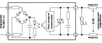
Stopping principle by DC injection. This system requires a constant voltage source to operate. Voltage requirements are not critical
The technique involves disconnecting the stator windings from the network and supplying rectified current to the windings. The passage of rectified current through the stator windings is accompanied by the formation of a fixed flux in the air gap between the rotor and the stator ring of the motor.
To achieve a value of this flux that can provide proper braking, the current must be approximately 1.3 times the rated current. The excess heat loss inevitably caused by this slight excess is usually compensated by a temporary pause after stopping the motor.
Criteria for applying the DC injection method
Since the current value depends on the resistance of the stator winding, the voltage at the rectified current source is low. Typically the source is a rectifier or speed controller circuit.
These rectified current sources must be adapted to the transient voltage surges that occur on the windings when disconnected from the AC power source.
The rotor movement here should be considered as sliding relative to a field fixed in space. The behavior of the motor is similar to that of a synchronous generator with unloading on the rotor. Therefore, the differences in the characteristics obtained during braking by introducing a rectified current are important, compared to a countercurrent circuit:
- Less energy is dissipated in the rotor resistors or in the rotor body. The process is equivalent to the mechanical energy released en masse during movement. The only power consumed from the network is the stator excitation.
- When the load is not controllable, the motor will not start in the opposite direction.
- If the load is controllable, the system operates continuously and keeps the load at low speed. That is, a deceleration factor is achieved, rather than complete braking. The performance is much more stable than that of a counterflow system.
On wound-rotor motors, the torque characteristics depend on the choice of resistors.
Option of braking resistors: 1 - heating sensor; 2 - metal shunt; 3 - high-temperature conductor; 4 - wire resistive element; 5 - temperature block; 6 - body
On squirrel-cage motors, the system allows you to easily adjust the braking torque of the electric motor, influencing the DC energy. However, the braking torque remains low if the engine is running at high speeds.
Types of electric braking
Electrical braking of locomotives is of great importance, providing savings in energy and brake pads, increasing speed on descents while increasing train safety.
The use of regenerative braking in some mountain areas makes it possible to reduce energy consumption for traction of trains by 10-15%. Traffic safety when using electric braking increases due to increased flexibility in controlling the movement of the train on descents, since it becomes possible not to use the automatic brakes of the train for a long time or to increase the charging time after braking.
To apply electric braking on AC electric locomotives, the reversibility property of electric machines is used. To do this, the excitation windings of all electric motors are disconnected from the armature windings, then all excitation windings are connected in series and connected to an adjustable voltage from the traction transformer. At the same time, each armature winding is connected to an electricity consumer:
if resistors are used as such a consumer, then rheostatic braking will be carried out;
If the armature windings of the electric motor are connected through an inverter and transformer to the contact network and other electric locomotives are energy consumers, we will obtain regenerative braking.
Concept of braking force in electric braking
On all electric locomotives, during rheostatic and regenerative braking, traction motors operate as generators with independent excitation. In generator mode, the braking torque on the TED shaft is expressed by the formula -
Мт = С·Iя·Ф,
This means that it can be adjusted and the braking force can be adjusted in two ways:
by changing the armature current - by changing the resistance of the braking resistor;
by changing the magnetic flux of the main poles (excitation windings) - using a controlled rectifier, which is powered by a power transformer.
APPEARANCE FOR WORK, ACCEPTANCE OF THE ELECTRIC LOGO.
The team starting work comes to the depot duty officer in accordance with the established schedule.
Members of the invading brigade must report to work rested. If it is impossible to go to work, you must immediately notify the depot duty officer or contractor. The electric locomotive crew is assigned or called to a trip after the end of the rest time accrued for the previous trip. This time should not be less than the product of the hours of working time of the previous trip by a factor of 2.51 minus the rest time at the point of turnover. Rest time may be reduced in the event of a shortage of crews, but by no more than one quarter of the required rest, and in any case should be at least 16 hours. If it is necessary to travel with fire, recovery and snow removal trains or to replace a driver who is ill on the way, a reduction may be possible rest time is up to 8 hours. The driver is called in such a way that he has time to travel to the depot and 1 hour to get ready.
When reporting to work, the driver must be in the prescribed uniform and have with him a certificate for the right to operate a locomotive, a certificate of admission to work on electrical installations, a locomotive driver's form, a technical form, a train schedule, extracts from the TPA, duty cards, test places and/ t, warning coupons, an extract from the order on permissible speeds on the road. After passing a medical examination, the driver reports his presence to the duty officer at the depot (or at the turnover point), receives from him a route sheet (“route”), learns from the duty officer at the depot the number of the electric locomotive that he needs to receive and the track number (depot ditch or PTOL ), where the electric locomotive is stationed; The duty officer from the depot also hands over a set of keys (input keys, for push-button switches, brake locking device condition. No. 367, boxes with tools, equipment, etc.), as well as the reversing handle of the driver’s controller. Then the locomotive crew undergoes pre-trip briefing to familiarize itself with the orders, instructions, operational instructions of the management of the Ministry of Railways, the road, the depot and signs in the order book.
Having checked the correspondence of the stamps on the reversing handle and the KU key to the number of the received electric locomotive, and having read the entries in the Technical Condition Log of the electric locomotive, the team begins to inspect the electric locomotive. The driver receiving the electric locomotive after TO-3 maintenance or routine repairs inspects all its components, apparatus and assemblies in more detail than during normal acceptance.
The responsibilities of the driver when accepting an electric locomotive include:
checking the date of the last maintenance-2, checking the ALSN and radio communication devices, familiarizing yourself with the comments of the team handing over the locomotive, and with the records of repairs carried out based on these comments. The receiving team is obliged to check the completion of TO-1 by the handing over team and if the work is not completed or performed with low quality, make an entry about this in the Logbook form TU-152.
Next, the driver must check the condition and operation of the main components of the mechanical, electrical and pneumatic equipment, fill the speedometer with tape, make sure that the scribes are present and working properly, that there are seals on the cover of the contact units and the brake pressure indicator, wind the watch and check its reading, and register the readings of the flow meter electricity, check the inventory and condition of tools, devices, signaling and fire-fighting equipment (check for seals on individual boxes, cabinets and fire extinguishers), safety equipment, and the contents of the first aid kit. The driver can assign part of his responsibilities to an assistant: acceptance of tools and equipment, checking bearing units. However, in this case, the driver conducts a control check of the assistant’s actions in accepting the specified components. The responsibilities of the assistant driver when accepting an electric locomotive include checking the availability of lubricants and cleaning materials, spare parts, auxiliary equipment not listed in the inventories, cleanliness of the premises and mechanical parts. When inspecting a locomotive, the driver first of all pays attention to the components and parts, the condition of which is regulated by the relevant paragraphs of the PTE. Having completed the acceptance of the electric locomotive, having checked that all the necessary work noted by the arriving driver has been completed, the driver records the completion time of acceptance in the Technical Condition Log of the electric locomotive, form TU-152, certifying the entries with his signature.
When accepting an electric locomotive that is braked by pneumatic brakes, its inhibition should be periodically monitored, since spontaneous movement is possible when the brakes are released. It is necessary to climb (and dismount) into the control cabin, holding the handrails with both hands, having first made sure that there is no rolling stock moving along the adjacent track; Before getting off the electric locomotive, you should inspect the ground near the stairs (by illuminating it with a flashlight at night), making sure that the place is level and there are no foreign objects on it.
In order to improve the technical condition of electric locomotives, the driver accepting the locomotive from another driver is obliged to check the delivery team’s performance of the appropriate cycle of maintenance work and give a rating of “satisfactory” or “unsatisfactory” in column 8 of the route of the driver of the delivery locomotive team; if the locomotive was accepted from repair or maintenance TO-3, then the driver at the end of the trip must hand over to the depot duty officer, along with the route, a warranty card from the repair team with deviations from the norm in the operation of the electric locomotive noted in it.
The sequence of bringing the electric locomotive into working condition is approximately as follows:
- turn on all switches on the distribution board (control panel);
— replenish the supply of compressed air in the main tanks;
— bring the pneumatic network into the state intended for train operation (except for the brake line);
— lift the pantograph, observing the requirements of safety rules;
— include BV-1, BVZ (KVTs contactor);
- launch auxiliary machines;
- turn on the brake line;
- test the action of the power circuit.
The operation of all equipment - electrical machines and compressors, furnaces, apparatus, sandboxes, brakes and lighting - is checked from both control cabins, usually starting from the head cabin along the expected direction of movement with the train. When checking, carefully observe the readings of measuring instruments and warning lights on the control panel. The approximate sequence of actions of the driver and the main points of the check are as follows.
1 . The pantograph should rise smoothly, and when lowering, break away from the wire sharply and then smoothly touch the shock absorbers. The total time for raising the pantograph is 7–10 s, and for lowering it is 3.5–6 s.
All pantographs are subject to inspection one by one. When the runner slowly moves away from the contact wire, the driver requires changing the adjustment of the pantograph valve or checking the static characteristics of the pantograph.
2. The condition of the battery is checked by turning on the cabin lighting lamps and the spotlight. If the battery is working properly, then within 1 minute there should be no noticeable decrease in the intensity of the lamps. The fans are stopped during this time.
3. The supply of compressors is checked by increasing the pressure from 0.7 to 0.8 MPa separately for each; The compressor supply in this pressure range must meet the requirements of the Auto Brake Operating Instructions (no more than 35 s).
4. Turn on the brakes ; check for leaks in the pressure and brake lines, as well as in the control circuit lines; check the operation of the air distributor. The check is carried out in accordance with the instructions for car brakes. The assistant driver checks the action of the brake lever transmission and the output of the brake cylinder rods (75-125 mm).
5. The operation of the fans is checked by ear. At high and low speeds, the hum should be uniform, but of different tones. On some electric locomotives, observing through the mesh of the high-voltage chamber door, they check the activation of the starting panel contactors, since if these contactors do not turn on, the starting resistors in the fan motor circuit may burn out. If the motor armature and fan are well balanced, the floor of the body does not vibrate when the fan motors stop.
6. The operation of cabin heating stoves is checked by touch. Turning the furnace contactors on and off is set by ear by pressing the corresponding buttons when the auxiliary machines are not working.
7. The operation of the control generators is checked at the moment the fans are started (the cabin lighting is first turned on). Normally, at the moment of startup, the lamps in the cabin flash brightly and their intensity remains higher than the original one when they were powered by the battery. For a reverse current relay, both pairs of contacts (main and additional) must be closed. The extinguishing of the POT lamp indicates normal operation of the generators and reverse current relays. Regardless of what speed the fans are turned on, the voltmeter on the switchboard should show a voltage of 50-52 V (in winter 52-54 V).
It is normal to experience slight sparking between the contacts of the vibration voltage regulator. When fans operate at low speed, sparking occurs at the contacts of both regulators. The charging current of a serviceable but slightly discharged battery can initially be 15-20 A, and then quickly decreases to 3-8 A.
When the fans stop in the cabins, the MOUTH (VL10) should light up. If the battery has a high voltage after charging, then the armature of the reverse current relay at the moment the rotation speed of the fan motors decreases can be repeatedly attracted and fall off, and the ROT lamp in the cabin flashes at this moment.
On electric locomotives VL10, VL10U with control panel PU-037, the G1 generator powers the control circuits, and the G2 generator charges the battery; The normal operation of the generators is indicated by the burning of lamps GU-1 and GU-2 (on the assistant driver’s console).
8. The operation of the converters is checked, including the Exciters button; In the cockpit, the warning lights P1, P2 go out. Check the switching on of the contactors of the starting panels, as well as the recovery circuits on the VL10 electric locomotives. To do this, with the high-speed switch turned on, the electric locomotive braked and fans operating at high speed, recovery circuits are assembled with a series connection of the armatures; Having moved the brake handle to several positions, check the operation of the circuits and converters using the ammeter readings in the motor excitation circuit. The difference in the excitation current of the motors of both sections should not exceed 20 A at any position.
9. The operation of light and sound signals is checked by turning on the buttons in turn: Dim cabin lighting, Bright cabin lighting, Instrument lighting, Right flashlight, Left flashlight, Dim spotlight, Bright spotlight, Chassis lighting, Signal, Whistle, etc.
When moving to another cabin, check the operation of the lighting in the corridors and engine rooms. The serviceability of the plug sockets is verified by turning on a portable lamp (on some electric locomotives, you must first turn on the Running gear lighting button in any of the control cabins).
10 . The sequence and clarity of the operation of the devices (sequence) can be checked by one person only by ear, and by two people - by direct observation of the devices. To do this, auxiliary machines and furnaces are turned off, the pantograph is lowered, and the electric locomotive is braked with a hand brake. During sequence testing, safety rules are strictly followed; To do this, all control buttons in the driver's cabin are turned off, the KU key is removed, which is used to unlock the push-button switch in the high-voltage chamber, after which the driver's assistant, at the driver's command, moves the main handle of the controller from position to position, and the driver checks the switching on of the contactors in accordance with the circuit table, which usually found on diagrams located in electric locomotive control cabins. No deviations in the operating order of the contactors are allowed. On two-section electric locomotives, the sequence is checked sequentially in both high-voltage chambers.
The sequence can also be checked in electric braking mode. To do this, the contactors of the converters are turned on, and the corresponding controller handles are installed in the braking positions. In braking mode, the operation of automatic control switches (ПВУ, АВУ) is also checked. So, if the air pressure in the brake line is increased to 0.27-0.29 MPa, then on electric locomotives VL10, VL10U, VL11 the BV must be turned off and the braking circuits must be disassembled.
During the sequence test, the air pressure in the lines and battery voltage are monitored. The drives of electro-pneumatic devices are designed for a minimum air pressure of 0.35 MPa and a voltage of 35 V. However, it should be remembered that the air from the main reservoirs may be used up and will have to be refilled from an external source. Reducing the voltage below normal is harmful to the battery cells. From another control cabin the sequence is checked by ear.
Having established that all devices are working properly, check the position of the switch blades of the traction motors and the busbar disconnector, and close the door of the high-voltage chamber. Then, having ensured that it is safe for the locomotive crew members and maintenance personnel, the driver unlocks the push-button switch in the cab and raises the pantograph.
11. Check the operation of the equipment under current . If necessary, start compressors and fans. The control switch and quick-acting switches are turned on, the reversing handle of the controller is set to the operating position and, after making sure that the movement of the electric locomotive does not threaten anyone, they sound a sound signal, the main handle is moved to the 1st position (the hand brake must be applied). If the brakes are released, the electric locomotive will start moving.
The current of the traction motors of the VL10 electric locomotives of the first production at the 1st position of the main controller handle will be 120-140 A; on electric locomotives of the overhead line 11 first releases, the armature current is about 400 A (excitation - 90 A), on the subsequent ones 240-260 A; the current value depends on the network voltage, the resistance of the starting resistors and the degree of their heating. It should be taken into account that the repair rules allow a deviation of resistance from the calculated one in the direction of increasing by 10%, and in the direction of decreasing by 7.5%.
They check the movement of the electric locomotive forward and backward, and also check the ammeter readings in both cabins, for which the assistant is in the other cabin at this time. On electric locomotives with electric braking, the readings of ammeters in the armature and field winding circuits are checked.
12. When the electric locomotive is standing outside the depot building, after the specified checks, they look at how the sandboxes from pneumatic and electro-pneumatic drives operate. Then the settling tanks and end hoses of the pneumatic lines are purged. This operation is performed by an assistant driver. He must remember that when the brake line is purged, the air distributor is activated, and therefore must make sure that no one is near the mechanical part of the electric locomotive. Pneumatic line coils are purged only when the compressors are running.
If all equipment operates normally, then the electric locomotive is considered suitable for train operation.
ACCEPTANCE OF AN ELECTRIC LOGO WHEN CHANGING CLIDES.
7. INSTRUCTIONS FOR MAINTENANCE OF ELECTRIC AND DIESEL locomotives IN OPERATION.
Acceptance of the electric locomotive.
• check the log of form TU-152 for the dates of the last maintenance-2, checks of ALS and PRS, CLUB, SOUTH, and familiarize yourself with it with the condition of the electric locomotive, with repairs performed according to the record of the driver who delivered it. If acceptance is carried out at the depot and the repairs have not been carried out, demand that the TChD perform it or replace the electric locomotive;
• check the completion of TO-1 by the team that handed over the electric locomotive; if it was not completed or was performed with poor quality, make an entry about this in the TU-152 log;
• inspect the mechanical part, paying special attention to the lack of rotation and the condition of the tires, the condition of the spring suspension, automatic coupling devices and safety devices against parts falling onto the track;
• check the presence of sand in the bunkers and the operation of sandboxes;
• carry out the work specified in the Instructions for the Operation of Brakes on Railway Rolling Stock.
Blow out pneumatic lines in accordance with local regulations.
• inspect the axlebox units, paying special attention to the reliability of bolt fastenings, drivers, rubber-metal elements, the absence of cracks in the housings and axlebox covers, check the heating temperature of the bearings by touch;
• inspect the condition of roof equipment from the ground;
• check the smooth operation of the device drives, the condition and fastening of the wires, the absence of air leaks, the condition of the fuses, the presence and serviceability of signal lamps, measuring instruments and lighting lamps, check the fastening and operation of auxiliary machines and the mobility of pantograph frames when lifting and lowering;
• check the operation of sound signals, spotlights, buffer lights, lighting;
• check the oil level in the compressor crankcases;
• check the readings of electricity meters;
• check the availability of tools, equipment, spare parts and materials, devices for collecting emergency diagrams, signal accessories, brake shoes (their quantity and numbers must be recorded in the TU-152 form log), the condition of the first aid kit, fire-fighting equipment, protective equipment, the condition of the equipment snow protection, cleaning and lubricants. When accepting the electric locomotive at the depot, replenish what is missing. When accepting on line - require the delivery team to draw up a report in the form TU-156;
• check the operation of ALSN (CLUB), SAUT, PRS and other devices that ensure traffic safety;
• check the operation of the comb lubricator and the brake line density control device;
• comply with the requirements of the fire safety instructions and check the condition of fireproof areas, avoiding the accumulation of rags, rags, oil and other flammable materials.
• if, during acceptance at the depot or at the turnover point, a malfunction is discovered that cannot be eliminated during acceptance, the driver is obliged to notify the person on duty at the depot (turnover point) and make an entry about this in the log of the TU-152 form. After this, by his order, the electric locomotive is replaced.
• sign for acceptance of the electric locomotive in the logbook form TU-152 and bear responsibility for its serviceability until the next delivery or until it is put into maintenance or repair.
Note: The procedure for accepting an electric locomotive is determined by local instructions approved by the head of the depot.
When accepting an electric locomotive issued for a passenger train driven by one driver, as well as in the case of changing locomotive crews without uncoupling the electric locomotive from the train, depending on local conditions, the acceptance volume may be reduced. In this case, as well as when electric locomotives are operated by several depots, the instructions must be approved by the head of the locomotive service of the road. When operating electric locomotives by locomotive crews of several roads, local instructions are approved by the heads of the locomotive services of these roads.
Delivery of the electric locomotive.
• carry out, if necessary, an additional check of faulty devices in order to clarify the nature of their condition and the causes of damage;
• complete the TO-1 cycle, cleaning the electric locomotive and in the TU-152 form log, make a detailed and legible record of all deviations in the operation of its components, equipment, circuits, ALSN (CLUB), SAUT, PRS and other safety devices, write off meter readings , indicate your last name, depot, date, time of delivery and certify the entry with a personal signature;
• in addition to making an entry in the TU-152 log, verbally inform the receiving team about the operation of the electric locomotive, especially about the observed signs of abnormal operation of individual components or circuits, the activation of backup systems, the use of emergency circuits;
• when handing over an electric locomotive operating on an emergency circuit, explain in detail its operation, especially if it is atypical. When the electric locomotive is handed over to the depot, the emergency circuit must be dismantled in whole or in part, if this is agreed upon with the senior foreman (foreman) or foreman;
• a malfunction discovered during delivery is eliminated by both teams;
• the team is responsible for untimely recording of an electric locomotive malfunction or its concealment,
• in the absence of tools, equipment, signal accessories, make an entry in the journal of form TU-152 and attach a report of form TU-156.
In daily activities, locomotive crews have significantly less time for acceptance, since it is carried out on station tracks in the departure park, often without uncoupling the electric locomotive from the train. In the 20-30 minutes usually allocated for acceptance, the team inspects and checks only the most basic things. Before proceeding with the acceptance of the electric locomotive, the driver will learn from the arriving crew how the locomotive as a whole and its individual components worked during the trip. If the handing over team notes that the current collectors, auxiliary machines, traction motors and rectifier units are working well, the driver devotes the bulk of the time allotted for acceptance to checking the mechanical equipment, bearing units and a quick inspection of the equipment installed in the high-voltage chamber, checking for the presence of seals on the protective and control equipment.
Under any conditions, the team carefully inspects the wheelsets, axle boxes, brake and spring systems, the hitchhiking device and the automatic coupling, since traffic safety primarily depends on the condition of these components, and also checks the operation of sandboxes, light and sound signals, measuring instruments and reserves. sand.
If during acceptance the electric locomotive is not uncoupled from the train, then the action of the brake lever transmission is checked using the auxiliary locomotive brake valve. The operation of the air distributor (in this case, an electric locomotive is monitored when testing the brakes of the entire train. In order to save time, the operation of fans and compressors is checked during a brake test; in this case, the compressor supply cannot be accurately determined, since the brake line cannot be disconnected.
During the acceptance process, it is necessary to periodically check the pressure in the main tanks and the battery voltage.
The assistant driver determines whether the electric locomotive has a supply of lubricants and cleaning materials, accepts signal accessories, brake shoes, fire-fighting and safety equipment, as well as tools.
The responsibilities of the assistant driver include checking the condition of the bearing assemblies of wheel pairs and traction motors. At the direction of the driver, he can take part in the inspection of other components of the electric locomotive. In severe frosts during acceptance, an assistant periodically blows out the moisture collectors and oil separators of the pneumatic lines.
If steam comes from the axle boxes of motor-axial bearings in wet weather, and in winter the snow melts on them, this indicates abnormal heating of the bearings. Such bearings are inspected through the upper hatch of the axlebox and the padding is sorted out.
During the delivery of an electric locomotive, the driver of the arriving crew usually spends most of the allotted time inspecting the internal equipment. At this time, the assistant driver replenishes the supply of lubricant, tidies up the interior of the body and wipes the mechanical parts. If the delivering driver makes comments about the unclear operation of a particular unit, then the receiving driver sets aside time to inspect this unit.
A malfunction discovered during the acceptance process is eliminated by the arriving team. If it is impossible to eliminate the malfunction on his own, the receiving driver notifies the duty officer at the depot (turnover point) to take action.
Climbing to the roof is permissible only on those tracks where the voltage has been removed (the mast disconnector is locked, the permissive signal light is on). You can climb to the roof only after making sure that both current collectors of the electric locomotive are lowered (for all sections of electric locomotives operating on a multi-unit system). While on the roof, do not touch the contact wire. Inspection and repair of roof equipment can only be carried out in good lighting. You must walk on the roof very carefully, especially in winter, when the walkways are covered with snow, frost and very slippery.
The arriving driver writes down in the technical condition log of the electric locomotive how the locomotive worked and what problems were noticed. The receiving driver reads this entry and, if it was noted that repairs are needed, checks whether they have been completed, and then signs for acceptance of the electric locomotive.
Electronic and super-synchronous engine braking
The effect of electronic braking is achieved relatively simply by using a speed controller equipped with a braking resistor. An asynchronous motor acts as a generator. Mechanical energy is dissipated in the limiting resistor without increasing losses in the motor itself.
The braking effect occurs when the motor reaches the top of the synchronous speed and moves to higher values. Here the asynchronous generator mode is actually initiated and the braking torque develops. The resulting energy losses are restored by the power grid.
A similar operating mode occurs on lift motors when lowering loads at rated speed. The braking torque is completely balanced by the torque from the load.
Due to this balance, it is possible to brake not by reducing the speed, but by bringing the engine into operation at a constant speed.
For the operation of wound-rotor motors, all or part of the rotor resistors must be short-circuited so that the motor does not develop movement significantly above the rated speed.
The supersynchronous system appears to be functionally ideal for limiting movement under load because:
- The speed remains stable and is practically independent of torque,
- Energy is recovered and renewed on the grid.
However, supersynchronous braking of electric motors only maintains one rotation speed, typically the rated rotation. Frequency-controlled motors use supersynchronous circuits, due to which the shaft rotation speed changes from a high value to a low value.
Supersynchronous braking is easily achieved by using an electronic speed controller, which automatically activates this system when the frequency is reduced.
Other braking systems
Rarely, but still there are single-phase braking systems. This technique powers the motor between two mains phases and connects the unoccupied terminal to one of the other two mains connections.
Stopping option by simple reverse switching - reversing the rotation field formed by the stator windings
The braking torque is limited to 1/3 of the maximum motor torque. This system cannot stop the engine at full load.
Therefore, this scheme is traditionally complemented by a countercurrent method. The single-phase blocking option is characterized by significant imbalance and high losses.
Electric motor braking is also used by weakening eddy currents. The principle at work here is similar to that used on industrial vehicles in addition to mechanical braking (electrical gearboxes).
Mechanical energy is dissipated in the speed reducer. Slowing down and stopping the electric motor is controlled by simply energizing the winding. A significant disadvantage of this method is a significant increase in inertia.
Braking of asynchronous motors
What is recuperation in relation to asynchronous machines? In this case, this is only one type of braking. The other two are:
- dynamic deceleration;
- counter braking.
Each of them has its own characteristics.
Regenerative braking of an asynchronous motor
An induction motor (IM) turns into a generator when the rotor slip in the stator field increases. This can be done in three ways:
- reducing the frequency of the supply voltage, at which the rotor begins to rotate at a speed faster than synchronous;
- in machines with two or more rotation speeds, when switching windings or changing the number of switched poles;
- in motors with a wound rotor, by changing the resistance included in the circuit of the rotor windings.
The amount of slip in all cases exceeds unity, and the machine goes into generation mode and returns energy.
Opposition
This method is rarely used due to the disadvantages associated with the need to swap phases with each other. This causes a change in direction of movement, but the operating current increases tenfold. In addition, it is necessary to stop further supply of voltage so that after braking the engine does not rotate in the opposite direction.
Dynamic braking of an asynchronous motor
This reduction in rotation speed is obtained by applying a constant voltage to the stator winding. The resulting magnetic field from the stator acts on the rotor windings. EMF appears in them, and current begins to flow. The strength of the braking torque that occurs when the power released is directly dependent on the rotation speed of the electric motor. The engine turns into a generator with short-circuited output terminals and supplies energy to the network.
Replacing or supplementing a mechanical brake with regenerative deceleration allows energy to be recovered for reuse. Recovery, as one of the ways to save raw materials and energy, allows you to increase the economy and efficiency of technological processes.
vote
Article rating
Schemes of capacitor braking of electric motors
Capacitor braking of asynchronous motors
The figure shows a diagram of turning on the motor with capacitor braking. Capacitors are connected in parallel to the stator winding, usually connected in a delta circuit.
When the motor is disconnected from the network, the discharge currents of the capacitors create a magnetic field rotating at a low angular velocity. The machine goes into regenerative braking mode, the rotation speed is reduced to a value corresponding to the rotation frequency of the excited field. During the discharge of capacitors, a large braking torque appears, which decreases with decreasing rotation speed.
At the beginning of braking, the kinetic energy stored by the rotor is quickly absorbed with a short braking distance. Braking is sharp, impact torques reach 7 Mn. The peak value of the braking current at the highest capacitance values does not exceed the starting current.
As the capacitor capacity increases, the braking torque increases and braking lasts to a lower speed. Studies have shown that the optimal capacity value lies in the range of 4 - 6 sleeps. Capacitor braking stops at a rotation speed of 30 - 40% of the rated speed, when the rotor speed becomes equal to the stator field speed due to free currents arising in the stator. In this case, during the braking process, more than 3/4 of the kinetic energy stored by the drive is absorbed.
To completely stop the engine according to the diagram in Figure 1, a, there must be a moment of resistance on the shaft. The described scheme is distinguished by the absence of switching devices, ease of maintenance, reliability and efficiency.
When connecting capacitors directly in parallel with the motor, you can use only types of capacitors that are designed for long-term operation in an alternating current circuit.
If braking is carried out according to the scheme in Figure 1 with the connection of capacitors after disconnecting the engine from the network, it is possible to use cheaper and small-sized metal-paper capacitors of the MBGP and MBGO types, designed for operation in direct and pulsating current circuits, as well as dry polar electrolytic capacitors (CE, KEG and etc.).
It is advisable to use capacitor braking with capacitors tightly connected in a triangle configuration for quick and accurate stopping of electric drives on the shaft of which a load torque of at least 25% of the rated motor torque is applied.
For capacitor braking, a simplified scheme can be used: single-phase connection of capacitors (Fig. 1.6). To obtain the same braking effect as with a three-phase connection of a capacitor, it is necessary that the capacitance of the capacitor in a single-phase circuit be 2.1 times greater than the capacitance in each phase in the circuit in Fig. 1, a. However, the capacitance in a single-phase circuit is only 70% of the total capacitance of the capacitors when they are connected three-phase.
Energy losses in the motor during capacitor braking are the smallest compared to other types of braking, so it is recommended for electric drives with a large number of starts.
When choosing equipment, it should be taken into account that the contactors in the stator circuit must be designed for the current flowing through the capacitors. To eliminate the disadvantage of capacitor braking - stopping the action until the electric motor stops completely - it is used in combination with dynamic magnetic braking.
Anti-inhibition braking.
Let us assume that the engine operates in the main (motor) mode with a rated load. When the motors are disconnected from the network, the torque M = 0, but the motor armature will continue to rotate for some time due to the kinetic energy of the rotating masses of the electric drive, i.e. the engine will run out.
To reduce the engine run-down time, back-on braking is used. For this purpose, the polarity of the voltage at the terminals of the armature winding is changed (the polarity of the field winding terminals must remain the same) and the supply voltage of the armature winding becomes negative (- U). But the motor armature, under the influence of the kinetic energy of the rotating masses of the electric drive, retains the same (positive) direction of rotation, and since the direction of the magnetic flux has not changed, the armature EMF Ea also does not change its direction and acts according to the voltage (-U), while the armature current is created the sum of the network voltage U and the armature emf Ea (Fig. 13.15, c):
where rt is the resistance of the resistor in the motor armature circuit.
Under these conditions, the electromagnetic torque will become negative.
Under the influence of the braking torque - Mt, the rotation speed of the armature decreases, reaching zero. If at this moment the armature circuit is not disconnected from the network, then the motor will reverse and its armature, under the influence of the torque that was previously braking, will begin to rotate in the opposite direction. In this case, the engine will switch to motor (main) mode with negative values of rotation speed and torque. To avoid unwanted reversal, the back-braking operation is automated so that at zero speed the armature circuit is disconnected from the network.